5
X
October 2017
A Case Study on Necessity of Retrofitting the
Existing Structure against Seismic Force
Aravinthan.k1,PadmanabanI2, Venkatasubramani.R3, A.P. Vignesh4, R.Kaviraj5,SanthoshP.S6, P.Sasi immanu7, P.Sasiimmanu,5
1, 2, 3,4, 5, 6, 7
Civil Engineering Dept., Dr. Mahalingamcollege of engineering and technology, Pollachi,Padmanaban.I, Civil Engineering Dept.,Sri Krishna college of technology,Coimbatore,
Abstract: Many structures located in seismically active zones which are not capable of withstanding against the seismic action. Based on current codes and provisions significant amount of research work has been carried out in recent years to develop various strengthening and retrofitting techniques to improve the seismic performance of existing structures.Here we are conducting a case study on single story building and evaluating the seismic force on the structure. If the structure does not withstand the seismic force then the structure is retrofitted by effective retrofitting technique. The experimental investigation is carried out for the existing structure (New mess block, EASA College of engineering and technology, Coimbatore). The total lateral force acting on the building is taken by the beams &columns, hence 2beam-column joint models were casted in theactual scale. The total forces acting on the structure is theoretically analyzed byusing the equivalentstatic force method, portal frame methodandsubstitute frame method.The models are tested inloading frame by applying Push pull jack. The comparison of ordinary structure (A model) and retrofitted structure (B model) is discussed here and the result was found good under lateral loads after retrofitting the beam column joint by GFRP sheets.
Key words- Earthquake resistant structure, Retrofitting, GFRP warping sheets, Loading frame, Push pull jack
I. INTRODUCTION
The application of FRP over the last decade there has been significant growth in the use of FRP composites as a construction material in structural engineering. These materials have proven themselves to be valuable for use in the construction of new buildings and bridges and for the upgrading of existing structures. FRPs will increase substantially in the future. For new structures, the application of FRPs is very promising and will depend on the ability to compete with the conventional materials. However, the life-cycle cost, including fabrication, application, protection and projected maintenance costs, is comparable and can be less than that of conventional materials. Charlotte A.C. Bouvier (2003)articulated about different retrofitting methods & techniques. They
arePolymer Concrete Composite, High-Performance Fibre Reinforced Cement Composite, Steel Cable, In-Situ Fabricated Jacket,
Prefabricated Methods, Sprayed Fibre Polymer, Elastomeric System, and Lead Rubber Bearing (LRB). The choice of the method depends on the building, on its specific requirements, as well as its condition, location, and geometry. Several methods should usually be considered and compared to find the appropriate best one. To provide greater flexibility in the retrofit scheme, several methods can be combined and implemented together, combining the advantages of each.M.D. EnamulHaqueNizam (2014)reviews
the application of FRPs in civil engineering.TheNatural fibers, such as sisal, flax, and bamboo, have been used only in experimental
applications to produce FRP products. However, it is expected that they will become more important in the construction industry due to their sustainability and recyclability.Three specific types of thermosetting resins are commonly used in the manufacture of building compositesPolyester resin, Epoxy resin, andVinylesters resin. K.Arjun(2016)Experimented on FRP was wrapped on the tension side of the slab using the cross-wrapping technique. The experimental study was conducted to test the reinforced concrete slabs. Reduced scale model slabs were designed as two-way slabs of 1070 mm x 1070 mm with a thickness of 90 mm and tested under uniformly distributed load. 8 mm diameter was provided along the two directions.The setup was carried out with a 25-ton loading frame, a loading jack was fixed on top of the specimen to apply load. To give the udl effect to the slab, loading channels were used such that the loads that were centrally applied were uniformly distributed on the slab. This experimental study investigates the cross type BFRP wrapping effect on ultimate load carrying capacity, deflection, and stiffness of slabs compared with control slab.
full wrapping technique around all the four sides of the beam is used as the method of retrofitting. The test beam was supported on roller bearings acting as supports. The specimen was placed on the two steel rollers bearing leaving 50 mm from the ends of the beam. The remaining 900 mm was divided into three equal parts of 300 mm. Loading was done by ahydraulic jack. Dial gauge was used for recording the deflection of the beams. The load was further applied to fracture load. The ultimate load or fracture load was taken as the load at which the needle of load dial on the UTM returned back.The result of the tests shows thatGFRP retrofitted beams had an ultimate load of 120 KN, which 89.6% greater than that of control specimen. Among the five sets of retrofitted beams, the beams retrofitted with PFRP had the least ultimate load carrying capacity and the value is 86.74 KN, which is 37.03% greater than the ultimate load capacity of control specimen.
The ultimate load capacity of the beams strengthened using carbon fiber sheets is increased by 125% when compared to that of control beam. Even though the beams retrofitted with CFRP sheets have the maximum ultimate load capacity, the cost of the material is high. The ultimate load capacity of GFRP, SFRP, and coir fiber sheet strengthened beams increased by 89.6%, 45.02%,and 37.9% respectively.The increase in ultimate load capacity is least for the beams retrofitted with Polypropylene fiber
sheets and is increased by only 37.03%.Retrofitting using GFRP sheets prove to be economical since its cost is only Rs. 300/m2 and
showed 89.6% increase in ultimate load capacity.Retrofitting using PFRP sheets is least recommended since its cost is high and increase in ultimate load capacity is less.The bonding between the FRP sheet and the concrete is intact up to the failure of the beam which clearly indicates the composite action due to FRP sheets.S. Arifuzzaman& M. Saatcioglu (2012) has prepared researchers for retrofitting of masonry buildings.The effectiveness of carbon fibre-reinforced polymer (FRP) sheets and anchors in retrofitting low-rise load bearing masonry walls have been investigated experimentally and the results are reported in this paper.The peak load resistance was limited to 120 KN. The wall survived up to 0.8% drift level. The wall experienced extensive diagonal crushing and a major load drop at 0.6% drift level due to the masonry crushing. The specimen resisted 100 KN of theload at 0.25% drift ratio.The wall maintained its load resistance after the failure of the bottom anchors until the 4.5% drift level is attained. Surface bonded CFRP sheets can be used as an effective retrofit technique for load bearing masonry walls. CFRP sheets prevent diagonal shear failure and improve wall shear capacity.
A. Summary
From the literaturestudy, it has been stated that Glass Fiber Reinforced Polymer (GFRP), is the most economical and has relatively good strength when compared to other types of polymers. Glass fibers are used for the majority of composite application because they are cheaper than the others. There are different forms known by names like
1) E-glass (the most frequently used),
2) S-glass (is a stronger and stiffer fiber with a greater corrosion resistance),
3) R-glass (is a higher tensile strength and modulus and greater resistance to fatigue and aging) and
4) AR-glass (an alkali-resistant glass used to reinforced concrete).
Retrofitting using GFRP sheets prove to be economical and showed 89.6% increase in ultimate load capacity.
II. THEORETICAL EXAMINATION OF MODELS
A. Preliminary data:
Type of structure - Single floor hostel mess building Seismic zone - Coimbatore (Zone 3)
Number of stories - 1 Floor height - 3.8m Imposed load - 3.5 KN/m2
Materials - M20 concrete & Fe415 steel Size of beam - (300*600) mm
Depth of slab - 150mm
{Unit weight of reinforced - 25 KN/m3
Concrete}
Type of soil - Rock soil
B. Building plan
The total area of the land = 2230.81 m2, Total covered area = 2037.66 m2 Height of the building= 3.8 m, Grade of concrete = M20, Grade of steel = Fe415
C. DETERMINATION OF SEISMIC FORCE BY EQUIVALENT STATIC LATERAL FORCE METHOD 1) Step:1 Total mass at floor levels
Total mass = Mass of (infill+column+slab+beam)+live load (Mass of infill &mass of columns are neglected)
Total mass = Mass of slab + mass of beam + live load
50% of live load can be taken if it is assumed above 3KN/m2
M = 6740.75 + 3679.53 +3.5 /2 *1817.1m2
M = 42219.53 KN
2) Step:2 Fundamental natural period
Ta = 0.075*h^0.75 = 0.075* (3.8)^0.75 Ta = 0.204 s
3) Step:3 Design base shear
VB =AhW
Ah = Z/2* I/R*Sa/g Z = 0.16 for zone 3
I = 1.5 (Educational building)
R = 5 (special RC moment resisting buildings) Sa/g = 1/Ta = 2.5 (from IS1893(part 1):2002) Ah = 0.16/2* 1.5* 2.5
Ah = 0.06
VB = (0.06)* (10842.4) VB = 650.54 KN
4) Step:4 Vertical distribution of shear
Q = VB *(Wi hi 2)/( Wi hi ^2)
Q = 650.54 KN
Total shear on column = 650.54/96 = 6.8 KN
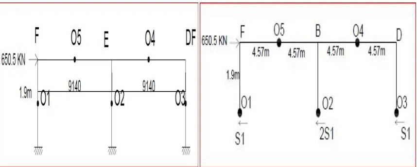
D. ANALYSING THE STRUCTURE FOR HORIZONTAL FORCE BY PORTAL FRAME METHOD: 1) Solution:
S1+ 2 S1+2 S1+ S1 = 650.5 KN 6 S1 = 650.5 S1= 108.41 KN 2 S1= 216.8 KN
2) Moments at columns:
MAF = MFA = MDC = MCD = S1 * 1.9 = 205.97 KNm MBE= MEB = 2 S1* 1.9 = 411.92KNm
3) BEAM SHEAR:
Take moment at F,
+4.57 V1 = 108.41* 1.9
V1 = 45.07 KN
{for anti clock wise force, moment is +ve} vice versa
Beam moment FO5 = V1 * 4.57 = 205.97 KNm
Column moment FO1 = S1 * 1.9 = -205.97 KNm
At F,
(4.57*45.07) + (4.57 V2) = (216.8*1.9) V2 = 205.95/4.57
V2 = 45.07 KN
Beam moment EO4 = 205.97 KNm
Column moment EO2 = -411.92 KNm
Take moment at D,
Beam moment DO4 =205.97 KNm
Column moment DO3 =-205.97 KNm
Mu (BEAM) = 205.97 KNm
Mu (COLUMN) = 411.92KNm
Vu = 45.07KN
E. Analyzing the structure for vertical force by substitute frame method:
Table- 2.5.1:Analysis Results of the structure for horizontal force (seismic)& vertical force
Force Beam
(KNm)
Column
(KNm)
Shear force (KN)
1. Horizontal force analysis by PFM 205.97 411.92 45.07
2.Vertical force analysis by SFM 232.7 166.25 156.5
3.Total force 438.67 578.17 201.57
Table 2.5.2: Design of Beam&Column, as per IS456 - 2000
Description Beam (600*300)
(KNm)
Column (450*300) (KNm)
1.Existing design of structure Ast:
25*2 = 981 mm2, 20*2 = 628 mm2,
16*1 = 201 mm2
20*2 = 314 mm2, Tot = 2124 mm2
Ast:
8*20 = 2513 mm2
Moment carrying capacity of existing design
Mu = 135.38 Mu =103.68
2.Moment carrying capacity required for structure after seismic analysis
Mu = 303.29 Mu = 474.5
Design of structure after
seismic analysis
Size = (300*850) Ast = 1982.4mm2
N = 8 (20 mm dia)
(600*450) 11340mm2 14(32mm dia)
3.Design of FRP sheet for seismic analysis
Size= 180mm Size= 265mm
III. EXPERIMENTAL ANALYSIS
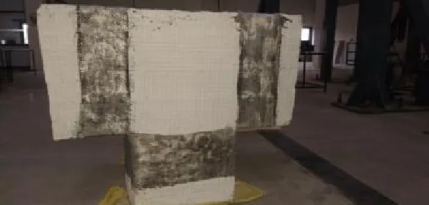
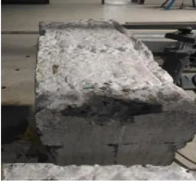
The actual scale of thebeam-column joint of 2 specimens was fabricated in the Concrete and Highway Laboratory of the EASA College of Engineering & Technology, Coimbatore. The specimens were cured for 28 days before testing.The first specimen is used as existing structure and the second specimen is used as aretrofitted structure. Both the specimen is tested inthestructural engineering lab, at Sri Krishna College Of Technology, Coimbatore.
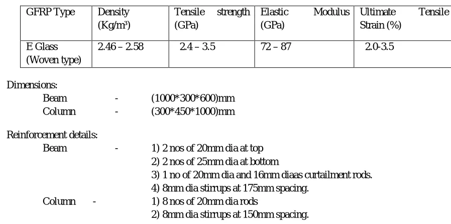
A. MATERIAL PROPERTIES:
Steel-Fe 415 grade of 8mm, 16mm, 20mm, 25mm.
[image:6.612.70.519.147.370.2]Strength -72.4 Mpa, Tensile Modulus -3180 Mpa, Ultimate Strain-5%, Tensile Strength -834 Mpa Elastic Modulus -82 Gpa, Elongation at Rupture -0.85%.
Table 3.1.1: Properties of GFRP (E glass)
Dimensions:
Beam - (1000*300*600)mm
Column - (300*450*1000)mm
Reinforcement details:
Beam - 1) 2 nos of 20mm dia at top
2) 2 nos of 25mm dia at bottom
3) 1 no of 20mm dia and 16mm diaas curtailment rods. 4) 8mm dia stirrups at 175mm spacing.
Column - 1) 8 nos of 20mm dia rods
2) 8mm dia stirrups at 150mm spacing.
B. Preparation of Test Specimen:
The specimen was retrofitted with one layer of Glass Fiber Reinforced Polymer (GFRP) sheets, for 180mm around beam on either side of thecolumn and for 265mm around column covering the joints. This is illustrated in Fig. 2. GFRP sheets were applied to the specimen. GFRP was applied using the wet lay-up procedure. The wall surface was first prepared prior to the application of GFRP.
1) The preparation involved,
a) Surface cleaning by wire brush, followed by air pressure to remove loose mortar,
b) Application of putty consisting of two-component epoxy and silica fume to cover head and bed joints and to smoothen the
wall surface,
c) Removal of any extra putty by a plastic putty knife,
d) After curing for a day, inspection of the surface and covering any noticeable air bubbles with putty using the same plastic
knife and
e) Finally sanding the surface withsandpaper after two full days of curing.
Once the wall surface was ready for the application of CFRP sheets, the sheets were cut to required sizes and applied on the wall surface.
2) The application involved the following steps:
a) Application of a layer of two-component epoxy with the hardener on the surface.
b) Application of GFRP whose fibers were parallel to the bed joint, saturated in epoxy.
c) Removal of extra epoxy and air pockets by means of a ribbed steel roller.
d) Again a layer of epoxy with hardener is applied over the GFRP sheets.
C. ExperimentalSetup, Instrumentation and Loading Program:
The test setup was designed to apply incrementallyincreased in lateral loading which is carried out in loading frame with ahydraulic jack. A total of 600 KN of theaxial load was applied. The specimen was instrumented to measure load and deflection by Load cell 1000KN Capacity and Linear Variable Displacement Transducers (LVDT).Displacements were measured mainly with CTs. The load was recorded by the MTS controller. The positions of transducers to record the force-displacement relationship are shown. An extra set of displacement transducers were attached on the opposite side of the wall as a backup. One no. of vertical transducers was
GFRP Type Density
(Kg/m³)
Tensile strength
(GPa)
Elastic Modulus
(GPa)
Ultimate Tensile
Strain (%)
E Glass (Woven type)
placed to measure vertical displacement of the Column. The loads are given in a gradual manner which is displayed on the monitor and the deflections due to load is also calculated in the deflection monitor. Thus the test can be carried out till cracks appear in the specimen.
IV. RESULT AND DISCUSSION
A. Test Results
The specimen is retrofitted with GFRP sheets on one side showed much better performance than the normal Specimen. The peak lateral load resistance increased significantly, developing 2 times the capacity of the conventional specimen.
[image:7.612.40.576.211.439.2]1) Specimen a (normal structure):
Table 4.1: Load vs. Deflection for existing structure.
S.NO LOAD( KN) FROM START ING LOAD (KN) CUMULA TIVE LOAD DEFLEC TION (mm) DEFLECTION-DISPLACEME NT(mm) FROM STARTING DISPLACE MENT (mm) CUMULATIVE DISPLACEME NT(mm) DRIFT (DEFLECTION/4 00)*100 (%)
1 25 0 0 4 0.5 0 0 0.125
2 32 7 7 5.37 1.87 1.37 1.37 0.4675
3 37 12 19 6.69 3.19 2.69 4.06 0.7975
4 39 14 26 7.54 4.04 3.54 6.23 1.01
5 45 20 46 11.19 7.69 7.19 10.73 1.9225
6 49 24 70 12.22 8.72 8.22 15.41 2.18
7 51 26 96 13.06 9.56 9.06 17.28 2.39
8 55 30 126 14.86 11.36 10.86 19.92 2.84
TOT
AL 30 10.86
2) Specimen b (retrofitted structure):
Table 4.1.2Load vs. deflection for retrofitted structure.
S.NO LOA D FROM STARTI NG LOAD (KN) CUMULAT IVE LOAD DEFLECTI ON DEFLECTION-DISPLACEMENT (mm) FROM STARTING DISPLACEM ENT (mm) CUMULATIVE DISPLACEMENT (mm) DRIFT (DEFLECTION/400 )*100 (%)
(KN) (mm)
1 3 0 0 18.01 15.51 0 0 3.8775
2 6 3 3 18.23 15.73 0.22 0.22 3.9325
3 19 16 19 20.4 17.9 2.39 2.61 4.475
4 25 22 41 21.44 18.94 3.43 5.82 4.735
5 29 26 67 22.43 19.93 4.42 7.85 4.9825
6 36 33 100 23.83 21.33 5.82 10.24 5.3325
TOT
AL 33 5.82
integrity of RC structures until the very end of the test, at which time toe crushing was observed at approximately 5.33% lateral drift.
IV. CONCLUSION
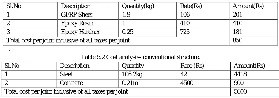
[image:8.612.81.528.277.434.2]Surface bonded GFRP sheets can be used as an effective retrofit technique for RC Structures. The GFRP-retrofitted specimen, with a single layer of GFRP in each direction, resisted twice the lateral force resisted by the existing structure. GFRP sheets prevent diagonal shear failure and improved the shear capacity. It also had an increase in lateral drift ratio up to 5.33%. The total material cost per joint is reduced by 6.25 times the conventional structure which requires large column and beams elements and heavily reinforced section. These hurdles are overcome by GFRP retrofitting technique. In spite of the significant research being reported on their structural mechanism and performance, there is still a lot of concerns regarding possible premature failure due to debonding, especially in zones of combined flexural and shear stresses. More research needs to be conducted addressing issues related to mechanics, design, and durability of FRP-retrofitted concrete and steel systems to ensure a proper use of FRP composites in seismic retrofitting applications. An improved understanding of the structural behavior of FRP fitted structures along with their failure mechanisms, which are often brittle in nature through experimental and numerical simulation, is necessary.
Table 5.1 Cost analysis-retrofitted structure.
Sl.No Description Quantity(kg) Rate(Rs) Amount(Rs)
1 GFRP Sheet 1.9 106 201
2 Epoxy Resin 1 410 410
3 Epoxy Hardner 0.25 725 181
Total cost per joint inclusive of all taxes per joint 850
.
Table 5.2 Cost analysis- conventional structure.
Sl.No Description Quantity Rate (Rs) Amount(Rs)
1 Steel 105.2kg 42 4418
2 Concrete 0.21m3 4500 900
Total cost per joint inclusive of all taxes per joint 5600
The load carrying capacity of theretrofitted structure is comparatively higher than the normal structure. So, thus the retrofitting of the structures may help in lateral load resistance in the seismic areas. So the structures built in the seismic areas can be retrofitted which is a very economical one and best technique when compared to the other techniques for an existing structure. The researchers should be increased in this type of techniques for decreasing the damage of earthquake forces on the structures.
REFERENCES
[1] K.Arjun, Dr. H.N.Jagannatha Reddy, Shubhalakshmi.B.S, (2016), Flexural Strength Of Two-Way RC Slabs Retrofitted With Basalt Fiber Reinforced Polymer(BFRP), International Journal Of Engineering Sciences & ResearchTechnology, Department of Civil Engineering, DayanandaSagar College of Engineering, Bengaluru, India, PP: 207-213.
[2] AnumolRaju,Lijianna Mathew (2013), Retrofitting Of RC Beams Using FRP, International Journal of Engineering Research & Technology (IJERT), Mookambika Technical Campus Toc H Institute of Science & Technology, Vol. 2 Issue 1.
[3] S. Arifuzzaman& M. Saatcioglu (2012) Seismic Retrofitting Of Load Bearing Walls By FRP Sheets & AnchorsDepartment of Civil Engineering, University of Ottawa, Ontario, Canada.
[4] M.D. EnamulHaqueNizam,Subrata Chandra Das,2014, Applications Of Fiber Reinforced Polymer Composites (FRP) In Civil Engineering (Bscorp), International Journal of Advanced Structures and Geotechnical Engineering ISSN 2319-5347,IJASGE 030317Department of Textile Engineering, MaanaBhashani Science and Technology University, Bangladesh. Vol. 03, no 03, pp 299-309.
[5] Charlotte A.C. Bouvier, (2003), Techniques of Seismic Retrofitting For Concrete Structures, Degree of Master in Civil and Environmental Engineering, Massachusetts Institute ofTechnology.
[6] Recent Development of Seismic Retrofit Methods Using AFRP (Japan Building Disaster Prevention Association-January, 2005). [7] Design Of Concrete Structures, Dr. B.C. Punmia, Ashok Kr. Jain, Arun Kr. Jain, Lakshmi Publications,2004.
[8] Earthquake Resistant Design OfStructures,PankajAgarwal, Manish Shrikandae,Prentice Hall Of India, 2006. [9] The Indian Standard Code Book IS 456:2000, Plain And Reinforced Concrete - Code Of Practice.
Fig 2.1 Building Plan Fig 2.2 Existing structure Beam-Column joint
[image:9.612.44.469.123.349.2] [image:9.612.50.484.404.596.2]Fig 2.4.1 Structural frame Fig 2.4.2 Portal Frame Method
[image:10.612.41.464.307.421.2]Fig 2.4.3 Member-FO1, FO5 Fig 2.4.4 Member-EO5, EO4, EO2
[image:10.612.202.411.478.596.2]Fig 2.5.1 Substitute Frame Method Fig 2.5.2 Bending Moment Diagram
Fig 2.5.3 Force with Moments Fig 2.5.4 Shear Force Diagram
[image:11.612.150.340.475.632.2]Fig 3.1.2 Normal specimen fig 3.1.3 Retrofitted specimen
Fig 3.1.4 Column reinforcement Fig 3.1.5 Beam reinforcement
[image:12.612.157.458.407.551.2]Fig 4.1.1 Cracks In Specimen B Fig 4.1.2 Breaking In Specimen B
(a) Transverse view. (b) Longitudinal view.
[image:13.612.293.493.331.517.2] [image:13.612.42.249.331.514.2]