Technology (IJRASET)
332
Performance Analysis of VARS Using Exhaust Gas
Heat of C.I Engine
N.Chandana reddy1, G. Maruthi Prasad Yadav2 1
PG Student, Mechanical Engineering Dept, St Johns College of Engg & Technology, Yemmiganur-518360, Kurnool(Dist), AP,
2
Associate Professor, Mechanical Engineering Dept, St Johns College of Engg & Technology, Yemmiganur-518360, Kurnool(Dist), AP,
Absract: In this paper the waste heat from C. I engine is suggested as one of the alternative energy source for refrigeration system. In this study, an overview of utilization of waste heat with a brief literature of the current related research is studied. The review covers the vapour absorption refrigeration system connected to the four stroke diesel engine. From the engine the two main areas through which the heat exhausted into the atmosphere are the cooling water and the exhaust gases. The heat available at exhaust gas is 5.5 KW and heat carried by cooling water is 12.54 KW.Vapour absorption refrigeration system is presented as an attractive substance that utilizes the waste heat from C. I engine. For the present investigation, a vapour absorption system associated with waste heat recovery from four stroke diesel engine is used to find out the coefficient of performance and energy Consumption. By using waste heat energy the coefficient of performance is increased to 23% and the energy consumption of 220 KJ/K is saved than the existing system. So it is estimated that recovery of waste heat reduces heat loss, improves performance of the system, saves the fuel, reduces the emission of exhaust gas, and is economically feasible. Also the area from which heat is lost to the surroundings decreases. From the experimental study, the vapour absorption refrigeration system can be obtained using heat that is expelled in to the atmosphere from C. I. engine. Through the study and by analyzing the obtained results it is evident that the waste heat based refrigeration system is economic, eco friendly with zero co2 emissions. Hence the system selected is technically proven, echo friendly and economically better.
Key words: Exhaust Gas, Waste Heat, Refrigeration, COP .
NOMENCLATURE:
Tg = Generator temperature
Ta = Absorber temperature
Tc = Condenser temperature
COP = coefficient of performance TR = Tones of refrigeration ∆W = Input work
∆Q cold = Heat removed from cold reservoir P actual = Actual power in watts
T ambient = Ambient temperature Qg = Enthalpy change in generator
Qe = enthalpy change in evaporator
Cp = specific heat of air
M = mass of ammonia solution ∆T = change in temperatures
Evoi= Volumetric efficiency of the engine
N= rated speed
ma= mass flow rate of the solution back to the absorber
mf= mass flow rate of fuel
Cpe= Specific heat at constant volume of exhaust gas
Technology (IJRASET)
333
Qw= Heat carried away by cooling water
Qe= Heat available at exhaust pipe
tcj= Temperature of water entering the cooling water jacket
tco=Temperature of water exiting the cooling water jacket
mw =Mass flow rate of water for a 4 cylinder diesel engine,
Cpw= Specific heat of water
ta =Temperature of the ambient air
I. INTRODUCTION
There exists today a worldwide concern about the best ways of using the depletable sources of energy and for developing techniques to reduce pollution. This interest has encouraged research and development efforts in the field of alternative energy sources, and the use of the usually wasted forms of energy. As the fuel prices continues to escalate, the relevance of efficient energy management is apparent to companies everywhere, from the smallest concern to the largest multinationals. The methods and techniques adopted to improve energy utilization will vary depending on circumstances. But the basic principles of reducing energy cost relative to productivity will be same. A large number of industrial processes covering most industrial sectors use significant amounts of energy in the form of heat, which are rarely efficient. Strictly speaking, all forms of energy are derived fossil from sun. However, The most common forms of energy-fossil fuels received their solar input ones agenda have changed their characteristics so that they are now in a highly concentrated form. Since it is apparent that these stored, concentrated energy forms are now being used at such a rapid rate that they will be depleted in the not-too distant future, we must begin to supply a large portion of our energy needs not from stored, but from non conventional sources as soon as possible. Energy is defined in classical thermodynamics as the capacity to do work. In our India energy is currently derived from four primary sources petroleum, natural gas and natural gas liquids, coal and wood. The supplies of these common energy sources except for wood are finite. Their lifetime is estimated very short. Abundand waste heat heat is available in the present world through exhaust of an I. C engine. It is well known that an IC engine has an efficiency of about 35-40%, which means that only one-third of the energy in the fuel is converted into useful work and about 60-65% is wasted to environment. In which about 28-30% is lost by cooling water and lubrication losses, around 30-32% is lost in the form of exhaust gases and remainder by radiation, etc. waste heat recovery system is the best way to recover waste heat and saving the fuel. Although there are various methods in which the emf is induced by directly called the sea beck effect or indirect methods such as Rankine cycle, Stirling cycle and refrigeration cycles. The present work discusses the exhaust gas heat recovery for I. C engine using a vapour absorption refrigeration system. In a Vapour absorption refrigeration system, a physiochemical process replaces the mechanical process of the vapour compression refrigeration system by using energy in the form of heat rather than mechanical work. The heat required for running the vapour absorption system can be obtained from that which is wasted in to atmosphere from the engine.
A. Vapour absorption refrigeration in road transport vehicles
Thisstudy includes an experimental investigation into the use of vaporabsorption refrigeration (VAR) systems in road transport vehicles using thewaste heat in the exhaust gases of the main propulsionunit as the engine energy source. This would provide an alternative to the conventional vapor compression refrigeration system and its associated internal combustion engine. The performance of a VAR system firedby natural gas is compared with that of the samesystem driven by engine exhaust gases. This showed that theexhaust-gas-driven system produced the same performance characteristics as the gas-firedsystem. It also suggested that, with careful design, inserting theVAR system generator into the main engine exhaust system neednot impair the performance of the vehicle propulsion unit. Acomparison of the capital and running costs of the conventionaland proposed alternative system is made.
Technology (IJRASET)
334
paper also considers other possible applications which might benefit from the use of ammonia as refrigerant. Horuz [2]study includes an experimental investigation into the use of vapor absorption refrigeration (VAR) systems in road transport vehicles using the exhaust waste heat in the exhaust gases of the main propulsion unit as the energy source. This would be an alternative source to the conventional vapor compression refrigeration system and its associated internal combustion engine. The performance of a VAR system fired by natural gas is compared with that of the same system driven by engine exhaust gases. This showed that the exhaust-gas-driven system produced the same performance characteristics as the gas-fired system. It also suggested that, with careful design, inserting the VAR system generator into the main engine exhaust system need not impair the performance of the vehicle propulsion unit. A comparison of the capital and running costs of the conventional refrigeration system and proposed alternative refrigeration system is made. Suggestions are made regarding working of the VAR system during off-road or slow running conditions. Jabinthflame[3] studied the refrigerating units currently used in road transport vehicle. This system utilizes power from the engine shaft as the input power to drive the compressor of the refrigeration system, hence the engine has to produce extra work to run the compressor of the refrigerating unit utilizing extra amount of fuel. This loss of power of the vehicle for refrigeration can be neglected by utilizing another refrigeration system i,e. a Vapour Absorption RefrigerationSystem(VARS). It is well known that an IC engine has an efficiency of about 35-40%, which means that only one-third of the energy in the fuel is converted into useful work and about 60-65% is wasted to environment. In which about 28-30% is lost by cooling water and lubrication losses, around 30-32% is lost in the form of exhaust gases and remainder by radiation, etc. In a Vapour Absorption Refrigeration System, a physicochemical process replaces the mechanical process of the Vapour Compression Refrigeration System by using energy in the form of heat rather than mechanical work. The heat required for running the Vapour Absorption Refrigeration System can be obtained from that which is wasted into the atmosphere from an IC engine.
G. Vicatos[4] observed that in the exhaust gases of motor vehicles, there is enough heat energy that can be utilized to power an air- conditioning system. Once a secondary fluid such as water or glycol is used, the aqua ammonia combination appears to be a good candidate as a working fluid for an absorption car air conditioning system.
In the paper, the waste heat from gas engine turbine can be used as the heat source for the absorption refrigeration system. The experimental analysis showed that performance of the integrated refrigerating system was greatly improved by using the waste heat of gas engine. Colbourne [5] summarized a study analyzing over 50 published technical documents comparing the performance of fluorinated refrigerants and HCs. A significantly higher number of tests showed an increase in performance when using HCs as compared to using fluorinated refrigerants (Colbourne and Suen,)[6].Similarly, Colbourne and Ritter[7] investigated the compatibility of non-metallic materials with HC refrigerant and lubricant mixtures. They performed experiments in compliance with European standards for the testing of elastomeric materials and ASHRAE material compatibility test standards. Setaro et al. [8] tested and compared the heat transfer and pressure drop through a brazed plate heat exchanger and a tube-andfin coil for two different refrigerants, R22 and R290 in an air-to water heat pump system. Qin et al. [9] developed an exhaust gasdriven automotive air conditioning working on a new hydride pair. The results showed that cooling power and system coefficient of performance increase while the minimum refrigeration temperature decreases with growth of the heat source temperature. System heat transfer properties still needed to be improved for better performance. Koehler et al. [10] designed, built and tested a prototype of an absorption refrigeration system for truck refrigeration using heat from the exhaust gas. The refrigeration cycle was simulated by a computer model and validated by test data.
II. SPECIFICATIONS OF ENGINE
The IC engine based on which the calculations are done is No of cylinders, n = 4.
Power, P = 60 bhp at 2000 rpm. Capacity, V = 1717cc.
No of strokes = 4. Fuel used = diesel. Air-fuel ratio, A/F =15:1
A. Waste Heat of the Engine
Technology (IJRASET)
335
1) Exhaust gas heat: Volumetric efficiency of the engine, Evoi= 70%.
Rated speed, N = 2000 rpm
Mass flow rate of air into the cylinder, ma = VN Evoi/2 = 0.001717x2000x0.7/2 ma=0.02m3/s.
Mass flow rate of fuel, mf = ma/ (A/F ratio) = 0.02/15 =0.001335 kg/sec
Total mass flow rate of exhaust gas, me= ma+mf = 0.021335 kg/s.
Specific heat at constant volume of exhaust gas Cpe= lkj/kgk. Temperature available at the engine exhaust, te = 300°C. Temperature of the ambient
air, ta = 40°
Heat available at exhaust pipe, Qe = me *Cpe (te-ta) = 0.021335xlx (300-40) =5.5Kw
2) Cooling water heat: Temperature of water entering the cooling water jacket, tcj=50°C.
Temperature of water exiting the cooling water jacket, tco=80°C.
Mass flow rate of water for a 4 cylinder diesel engine, mw=0.1 kg/s. Specific heat of water, Cpw=4.18 kj/kgk
Heat carried away by cooling water Qw = mw*Cpw (tC0-tcj) = 0.1x4.18x (80 -50) = 12.54 kW.
B. Final Value
Heat available at exhaust gas = 5.5 kW Heat carried by cooling water = 12.54 kW
III. PERFORMANCE PARAMETERS
A. Calculations
1) Coefficient of Performance (COP): The coefficient of performance or COP, of a refrigeration system is the ratio of the heat removed from the cold reservoir to input work.
Is the heat moved from the cold reservoir (to the hot reservoir). Is the work consumed by the heat pump.
Domestic and commercial refrigerators may be rated in kJ/s, or Btu/h of cooling. Commercial refrigerators in the US are mostly rated in tons of refrigeration, but elsewhere in kW. One ton of refrigeration capacity can freeze one short ton of water at 0 °C (32 °F) in 24 hours. Based on that:
Latent heat=333.55 kJ/kg
Heat extracted = (2000) (144) / 24 hr 1 ton refrigeration =3.517 kW
The performance of the vapour absorption refrigeration system is given by the following formula Coefficient of Performance (COP) = [ ]
Where Te=evaporator temperature
Tc=condenser temperature
Tg= generator temperature
2) System pressure: From the specification of Electrolux refrigeration, the system pressure = 10 Kg/cm2
3) Energy calculation: Amount of energy released when one mol of ammonia reacts with one mol of water
NH3 (gas) + H2O (aq) <==> NH4OH (aq)
Enthalpy of reaction = -50 KJ/mol
Technology (IJRASET)
336
4) Time required: The heat energy available at exhaust is. 5.5KW = 5.5 KJ/s
From the company specifications of the Electrolux system Power required at the generator is (Pactual) = 80 W
So one minute of heating gives 5.5 x 60 = 330 KJ of energy.
This implies that by supply of waste heat for about 1 mins, 330KJ of energy can be produced. This is more than sufficient to release one mole of ammonia vapour from the solution.
5) Mass of ammonia in solution
Molar concentration of saturated ammonium hydroxide = 17 mol/ l Molecular mass of ammonia = 17 g/mol
Concentration of ammonia in one liter of solution = 17 x 17 =289 g/l
Volume of ammonium hydroxide solution in the system = 3/4th volume of the generator tube Volume of one generator tube = (π d2)/4 x 1
Volume of ammonium hydroxide solution = 3/4 x 2 x (πd2)/4 x100 = 150 cm3 = 0.15 litres Mass of ammonia in the solution = 289 x 0.15= 43 g
B. Cooling load calculation
The propose of load estimation is to determine the size of the refrigeration equipment that is required to maintain the design conditions during the periods of maximum outside temperatures. The design load is based on inside and outside design conditions and it is in refrigeration equipment capacity to produce and maintain satisfactory condition.
Enthalpy change in generator,
QG = mass x latent heat of vaporisation
= 0.043 x 1372 KJ/Kg =58.KJ
This is the amount of energy absorbed at the generator to liberate ammonia vapour from solution.
C. Theoretical temperature drop
Assuming the fridge is empty with only air inside to obtain the max temperature drop Volume of cooling cabin = 5 liters
Hence volume of air inside the cabin = 0.005m3 Density of air = 1.15 Kg/m3 (at sea level, 30oc) Mass of air inside the cabin = 0.0059 Kg Specific heat of air (cp) =1.005 kJ/kg K
Assuming ambient temperature (Tamb) = 40oC
= 313 K
Enthalpy change of refrigerant during evaporation = Enthalpy change of air inside cabin + Enthalpy change of ammonia vapour
Assuming a theoretical COP of 0.1 COP = QE /QG
QE = 0.1 x 58 =5.8 KJ
This much energy is absorbed from the evaporator cabin QE = m (air) x cpx change in temperature
5.8 = 0.067 x 1.005 x (313 - Te) + 0.043 x 4.75 x (313 - Te)
Te = 291.51 K =18.51 oC
This is the theoretical temperature drop which can be obtained from the modified system.
IV. RESULTS AND DISCUSSION
A. Experimental setup
Technology (IJRASET)
337
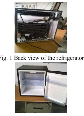
Temperatures at various locations were measured using digital thermo meter .various locations at which temperatures are measured .
[image:7.612.238.377.100.292.2]Fig. 1 Back view of the refrigerator
Fig:2 Front view of refrigerator
B. Experimental Procedure
The parts of Electrolux refrigeration system are fabricated and assembled. Electrolux refrigeration system consists of the following parts and as shown below:
They are (a).Absorber pipe (b) Condenser (c) Generator (d) Evaporator (e) Generator pipe
For refrigeration system we have considered vapour absorption refrigeration system. This system is more useful and applicable to our system. The machine is to provide 5 liters capacity of refrigerator with the components. The Electrolux refrigeration system obtained was modified in order to accommodate the waste heat fixing the generator tube to the exhaust pipe. The pipe coming from engine exhaust is connected to the one end of the generator tube and the other end of the generator tube is free to atmosphere. When the engine starts working the exhaust gases are made to pass through the generator where the heat is recovered, which later escapes in to atmosphere.COP is calculated using generator, absorbent, condenser & evaporator temperatures for considered 5 liters evaporative cabin & represented in the table 7. 1 for different generator temperatures
Table 1 COP at various generator temperatures
The performance of the vapour absorption system varies considerably with the generator and other main components of the system. To illustrate these effects the calculated values for different temperatures of proposed and existing systems have been plotted on the graphs. Based on determined results various graphs are drawn with different parameters.
Tg(oK) Ta(oK) Tc(oK) Te(oK) COP
[image:7.612.197.418.481.567.2]Technology (IJRASET)
©IJRASET 2015: All Rights are Reserved
338
Graph 1 Effect of generator temperature on COP
The graph 1 is drawn for the waste heat based refrigeration values of the generator temperature to the coefficient of performance. These values are taken by the comparison of the conventional system to the waste heat based refrigeration system of the values of cooling temperature. Maximum COP of 1.72 is obtained at 4oK of generator temperature using un-conventional system where as it is 2.37 using proposed system. From graph it is observed that the coefficient of performance is increased as the generator temperature is increased. Comparing the both COP of proposed system is more effective than that of existing system.
Graph 2 Effect of Evaporator temperatures on COP
The graph 2 gives the comparison of COP and evaporator temperature values for proposed system and existing system. It is observed that with increase in evaporator temperature, the COP values for each system decreases.
The graph shows that COP values decrease with difference of 0.04 up to 2˚k and after that the graph diminishes smoothly on increasing the evaporator temperature. Comparing the both, COP of proposed system is more effective than that of conventional system.
Graph 3 Effect of condenser temperature on COP
1.69 2.03
2.37 2.41
1.23
1.42 1.72
1.86 0 0.5 1 1.5 2 2.5
0 2 4 6
C
O
P
Generator temperature (°K)
proposed system Existing system
2.41 2.37 2.03
1.69 1.86 1.72
1.42 1.23
0 0.5 1 1.5 2 2.5 3
0 2 4 6
C
O
P
Evaporator temperature (°K)
proposed system
Existing system
1.23 1.42
1.72 1.86
1.69 2.03
2.37 2.41
0 0.5 1 1.5 2 2.5 3
0 2 4 6
C
O
P
Condenser temperature (°K)
Existing system
Technology (IJRASET)
©IJRASET 2015: All Rights are Reserved
339
Based on the data, graph 3 shows the variation of coefficient of performance with generator temperature. With increase in condenser temperature causes increase in system performance for both the systems. The COP up to 3˚k increases sharply and later that increment of performance is approximately constant.
The graph shows that at certain limit of condenser temperature of 4˚k, the COP obtained is 2.41 for non conventional system and at same temperature for conventional system the COP obtained is 1.86.
Graph 4 Effect of absorber temperature on COP
Graph 4 compares the performances of existing system and proposed system. It shows that the performance of both the systems decreases as increase in absorber temperature. The optimum value of cop 2.41 is achieved at absorber temperature 1˚k. Graph also show that with increase in absorber temperature decreases the COP of both the systems. From the analysis of both the systems proves that the performance of the nonconventional system is more effective than the conventional system.
Graph 5 Variation of COP with time
Referring to graph 5, it is seen that the coefficient of performance of the proposed and existing system decreases as the time increases. The performance of the conventional system is obtained is 1.73 at time of one second and for the non conventional system at the same time is 2.42. From the graph comparing the coefficient of performance of both the systems at the same time, the optimum value of COP is attained by non conventional system and 23% more than conventional system.
Graph .6 variation of cooling temperature with power consumption
1.86 1.72
1.42 1.23
2.41 2.37 2.03 1.69 0 0.5 1 1.5 2 2.5 3
0 2 4 6
C
O
P
Absorber temperature (°K)
Existing system
1.86 1.72
1.42 1.23 2.41 2.37
2.03 1.69 0 0.5 1 1.5 2 2.5 3
0 2 4 6
C O P Time(sec) Existing system proposed system 16 12
10 8
18 14 12 10 0 5 10 15 20
0 0.02 0.04 0.06
Technology (IJRASET)
©IJRASET 2015: All Rights are Reserved
340
The graph 6 is drawn between the cooling temperature and power consumption. From the data it is clear that with the increase of power consumption there is diminishing of cooling temperature for both the systems. But the cooling temperature obtained for proposed system is better than the existing system. The cooling temperature values of nonconventional system at every increment of power consumption are better than 11% than the conventional system. The optimum values attained by both systems at power consumption of 0.01 are 18 and 16 for nonconventional and conventional systems.
Graph.7 effect of generator temperature on evaporator temperature
The graph 7 is drawn from data of the evaporator temperature and generator temperature. It shows that with the increase in generator temperature there is no change in evaporator temperature for existing system and at same generator temperature for proposed system evaporator temperature diminishes with small difference at every increment of generator temperature. It is observed that the generator temperature is increased when the evaporator temperature is decreased and more cooling effect is produced. So the temperature values of the non- conventional system are more effective when compared to the conventional system.
Graph 8 Variation of Energy consumption with time
The graph 8 is drawn for the practical values of the energy consumption with time. The optimum value of energy consumption attained by conventional system and non conventional system are 246KJ/K and 427KJ/K at four seconds of time. It is observed that the energy consumption is increased as the time increased. So the time will affect energy consumption. So when both are compared the temperature values of the non- conventional is more effective when compared to the conventional system.
V. CONCLUSIONS
Experimental studies have been carried out to evaluate the system performance under various conditions. A separate experimental set up has been used for determining the various performance parameters. From the investigations, the following conclusions are drawn:
A. In the present work the vapour absorption refrigeration system running with waste heat as an energy source which is supplied to the generator instead of conventional energy, which contains 5 liters capacity of evaporative cabin.
B. The COP of the system is increasing with increase of generator temperature and condenser temperature, and trend is reverse with increase of absorber temperature and evaporator temperature.
C. By using waste heat input in the form of heat at the generator pipe the maximum COP of the system is obtained as 2.41.
D. The COP of the modified cycle of proposed system is nearly 23% greater than existing.
E. The analysis of both cycles proves that the performance of the proposed system is higher than existing system.
103 154
198 246
243 298
365 427
0 100 200 300 400 500
0 2 4 6
Technology (IJRASET)
©IJRASET 2015: All Rights are Reserved
341
F. A maximum power consumption of 42.38% is saved using proposed system compared to existing system.
G. The proposed refrigeration system using waste heat of C.I engine is superior to the existing conventional refrigeration system.
REFERENCES
[1]. Andy Pearson (2008) refrigeration with ammonia and hydro carbons, Int journal of refrigeration, 545-551. [2]. I. Horuz (1999) vapor absorption in road transport vehicles, Journal of energy engineering, Vol. 125, No. 2, 48-58 [3]. Jabnithflame (2011) Development of an A/C system using waste heat of an I.C engine
[4]. G Victos, J Gryzagoridis & S Wang, “A car air conditioning system based on an absorption refrigeration cycle using energy from exhaust gas of an internal combustion engine”, journal of energy in southern Africa, Vol 19, issue 4, November 2008, pp.6-11.
[5] Colbourne, D., 2000. An overview of hydrocarbons as replacement refrigerants in commercial refrigeration and air conditioning. Refrigeration Northern Ireland Centre for Energy Research and Technology.
[6] Colbourne, D., Suen, K.O., 2000. Assessment of performance of hydrocarbon refrigerants. In: Proceedings of the Fourth IIRGustav Lorentzen Conference on Natural Working Fluids, Purdue, USA.
[7] Colbourne, D., Ritter, T.J., 2000. Compatibility of Non-Metallic Materials with Hydrocarbon Refrigerant and Lubricant Mixtures. IIF-IIR- Commission B1, B2,E1 and E2 – Purdue University, USA
[8] Setaro, T., Boccardi, G., Corberan, J.M., Urchueguia, J., Gonzalvez, J., 2000. Comparative study of evaporation and condensation of propane and R22 in a brazed plate heat exchanger and a tube and fins coil. In: Proceedings of the Fourth IIR Gustav Lorentzen Conference of Natural Working Fluids, Purdue, USA, pp. 233–238 [9] Qin F, Chen J, Lu M, Chen Z, Zhou Y, Yang K. Development of a metal hydride refrigeration system as an exhaust gas-driven automobile air conditioner. Renewable Energy 2007;32:2034–52.
[10] Koehler J, Tegethoff WJ, Westphalen D, Sonnekalb M. Absorption refrigeration system for mobile applications utilizing exhaust gases. Heat Mass Transfer 1997;32:333–40.
[11]. William H Severens and Jullian R. Fellows, Air Conditioning & Refrigeration (Willey International-1958)
[12]. Richard G. Jordan and Gayle B. Priester Refrigeration & Air Conditioning (Prentice Hall Of India Pvt Ltd.,New Delh-1965).