Volume 72– No.5, May 2013
Stability Enhancement with SVC
Amit Debnath
Dept. of Electrical EngineeringTripura University (A Central University)
Joseph Rualkima Rante.
Dept. of Electrical Engineering Tripura University (A CentralUniversity)
Champa Nandi
Assistant Professor Tripura University (A CentralUniversity)
ABSTRACT
This paper deals with Power flow, which is necessary for any power system solution and carry out a comprehensive study of the Newton- Raphson method of power flow analysis with and without SVC. Voltage stability analysis is the major concern in order to operate any power system as secured. This paper presents the investigation on N-R power flow enhancement of voltage & angle stability with & without FACTS controllers such as Static Var Compensator (SVC) device. The Static Var Compensator (SVC) provides a promising means to control power flow in modern power systems. In this paper the Newton-Raphson is used to investigate its effect on voltage profile and angle stability with and without SVC in power system. Simulations have been implemented in MATLAB Software and the IEEE 57-bus system has been used as a case study. Simulations investigate the effect of voltage magnitude and angle with and without SVC on the power flow of the system. This survey article will be very much useful to the researchers for finding out the relevant references in the field of Newton-Raphson power flow control with SVC in power systems.
General Terms
MATLAB Software Toolbox, Newton-Raphson method, Power flow, Power flow with SVC FACTS Controller Algorithm, Reactive Power Compensation.
Keywords
Newton-Raphson method, Power flow, SVC FACTS Controller, Reactive Power Compensation.
1.
INTRODUCTION
As the power systems are becoming more complex it requires careful design of the new devices for the operation of controlling the power flow in transmission system, which should be flexible enough to adapt to any momentary system conditions. The operation of an ac power transmission line is generally constrained by limitations of one or more network parameters and operating variables by using FACTS[3] technology such as SVC (Static Var Compensator), the bus voltages, line impedances, and phase angles in the power system can be regulated rapidly and flexibly. N-R power flow is very important tool for the analysis power systems and it is used in operational and planning. The main objective of power flow is calculating unspecified bus voltage angles and magnitudes.
The FACTS controllers offer a great opportunity to regulate the transmission of alternating current (AC), increasing or diminishing the power flow in specific lines and responding almost instantaneously to the stability problems. The potential of this technology is based on the possibility of controlling the route of the power flow and the ability of connecting networks
that are not adequately interconnected, giving the possibility of trading energy between distant agents. Flexible Alternating Current Transmission System (FACTS) is static equipment used for the AC transmission of electrical energy. It is meant to enhance controllability and increase power transfer capability. It is generally power electronics based device. The FACTS devices can be divided in three groups, dependent on their switching technology: mechanically switched (such as phase shifting transformers), thyristor switched or fast switched, using IGBTs. While some types of FACTS, such as the phase shifting transformer (PST) and the static VAR compensator (SVC)[4] are already well known and used in power systems, new developments in power electronics and control have extended the application range of FACTS[6]. This paper presents the performance of Newton-Raphson power flow analysis for IEEE-57bus system with and without SVCC FACTS controller and verifies the voltage & Angle Stability of a power system.
2.
NEWTON-RAPHSON POWER FLOW
APPROACH
Load-flow studies are very common in power system analysis. Load flow allows us to know the present state of a system, given previous known parameters and values. The power that is flowing through the transmission line, the power that is being generated by the generators, the power that is being consumed by the loads, the losses occurring during the transfer of power from source to load, and so on, are iteratively decided by the load flow solution, or also known as power flow solution. In any system, the most important quantity which is known or which is to be determined is the voltage at different points throughout the system. Knowing these, we can easily find out the currents flowing through each point or branch. This in turn gives us the quantities through which we can find out the power that is being handled at all these points [2].
Let F(x) be a nonlinear function of (x) Where (x) = a set of variables
If F(x) is expanded in terms of Taylor’s series up to terms containing first derivatives only around an initial set of points
x o
, F (x) can be written as:) x ( ) x o ( F ' )
x o ( F ) x (
F
(1) Where
) xo (
F
=
Value of the function at,x o
)xo (
F '
=
First partial derivatives of F (x) atx o
x
=
Changes in the values of variablesVolume 72– No.5, May 2013
0 ) x ( ) x o ( F '' )
x o ( F ' )
x (
F '
(2) Where
) xo (
F ''
=
Hessian of F(x) atx o
After rearranging,
x
)
F
(
xo
)
'' 1
F
(
xo
)
'
(
(3)
x
x
x
i(k)) k ( i ) 1 k (
i
(4)
Equations (3) arid (4) are the basic relations for the development of second order Newton formulation.
3.
POWER FLOW CONTROL
The power transmission line can be represented by a two-bus system ―k and ―m in ordinary form. The active power transmitted betweens bus nodes k and m is given by [2, 9]:
X
)
m
k
sin(
V k
V m
P
(5)
Where
Vm
&
Vk
are the voltages at the nodes,
k
m
the angle between the voltages and X the line impedance. The power flow can be controlled by altering the voltages at a node, the impedance between the nodes and the angle between the end voltages [5]. The reactive power is given by:X
)
m
k
cos(
Vk
Vm
X
V2
k
P
(6)
4.
STATIC VAR COMPENSATOR
[image:2.595.56.279.74.189.2]Basically, the SVC consists of a thyristor-controlled reactor (TCR) in parallel with a capacitor bank. The firing-angle control of thyristor enables the SVC to have very fast response. It provides fast reactive power compensation, improves the bus voltage profiles, increases system stability margin and damps power system oscillations [4, 5, 9, 12].
Fig 1: A basic schematic for an SVC
Reactive power [7] compensation is necessary for voltage regulation, stability enhancement and for increasing power transmission capability [2, 12]. Both the STATCOM and the SVC have been used to provide variable shunt reactive
compensation [1]. They provide rapidly controllable, automatic variable shunt compensation at the appropriate buses in the power system [4]. Moreover, these devices can be placed in the network more easily than the generating units without any danger of the increasing the faults. The two most popular configuration of this type of shunt controller are the fixed capacitor (FC) with a thyristor controlled reactor (TCR) and the thyristor switched capacitor (TSC) with TCR. Among these two setups, the second (TSCTCR) minimizes stand-by losses; however from a steady-state point of view, this is equivalent to the FC-TCR. In this paper, the FC-TCR structure is used for analysis of SVC which is shown in figure 1. The TCR consists of a fixed reactor of inductance L and a bi-directional thyristor valve that are fired symmetrically in an angle control range of 90° to 180°, with respect to the SVC voltage.
4.1
Operating Principle
The current through the reactor can be regulated by closing the thyristor switch at any point between 0º to 90º from the start of the voltage wave. When the switch closes at 0º, a full current wave passes through the reactor. This reactor current, as per design, is higher than the capacitor current at the line voltage. The two currents are in phase opposition, giving a resultant, which is inductive. The SVC [9, 10] is operating in the inductive mode. As we advance the firing angle, the inductive current wave form shrinks and the current reduces. Beyond the matching point, the resultant of the two currents is capacitive. The following three important features to be noted: 1. Since the inductive current comes in a truncated form, it brings in harmonics, which are a regular feature here. 2. The thyristors are self-commutating, that is, the inductive will be off, at the end of the current wave by itself.
3. Under a static operation, the regulation is of an instant type and can jump from a high capacitive output to a high reactive output with a time lag of hardly a few cycles, if required by the power system.
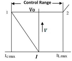
Let us refer to the basic schematic of an SVC as shown in Figure2
[image:2.595.362.516.481.611.2].
Fig 2: Operating Control Range of SVC
The reactive power output of the reactive is higher than that of the capacitor, at rated voltages on both. The reactor output is regulated. If the system is overloaded and requires capacitive current support the reactor current is reduced below that of the capacitor current so that the net outflow from the SVC is capacitive. The maximum capacitive current, that the SVC provides, is I maxc with the reactor current falling to zero. The system changes to light load conditions and the system voltage rises. Some reactive current has to be added to hold down the system voltage, SVC [11] then counter-balances the capacitive current fully and produces a resultant lagging Transformer
L/2
Switch C
Current Limiting Reactor CLR
L/2
1
Vo
2Volume 72– No.5, May 2013 current. It reachesI maxc , which the SVC can produce.
Please note that under this condition, the SVC is producing a resultant current of I maxl I maxc beyond point 2, the system voltage will keep on rising. The control range of the voltage with the SVC lies between points 1-2.
[image:3.595.56.279.155.345.2]4.2
Characteristic of SVC
Fig 3: V-I characteristics of SVC
A typical terminal voltage versus output current of a static Var compensator with a specific slope is shown in Fig.5.In most applications, the static Var compensator [12] is not used as a perfect terminal voltage regulator, but rather the terminal voltage is allowed to vary in proportion with the compensating current. This regulation slope is defined as:
I max
L
V max
L
I max
c
V max
c
Slope
(7)
The regulation slope allows:
To extend the linear operating range of the compensator
To improve the stability of the voltage regulation loop
To enforce automatic load sharing between static Var compensator as well as other voltage regulating devices.
The voltage at which the static compensator neither absorbs nor generates reactive power is the reference voltage Vref (Fig.5).In practice, this reference voltage can be adjusted within the typical range of ±10%.The slope of the characteristic represents a change in voltage with compensator current and therefore, can be considered as a slope reactance
XsL. The SVC response to the voltage variation is, then, determined from:
Isvc * XSL V
VT ref
(8)
5.
SVC Power Flow Model
Two SVC models are presented in this section. These models differ from the usual representation of SVC [10] as a voltage source. They are based on the concept of variable susceptance.
These are the shunt variable susceptance model and the firing-angle model, where the SVC variables are combined with bus voltage magnitudes and angles of the network for obtaining power flow solution. These SVC models are presented in the following sub-sections.
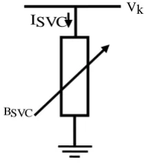
5.1
Shunt Variable Susceptance Model
Fig 4: Variable shunt Susceptance model of SVC
In practice the SVC can be seen as an adjustable reactance with either firing-angle limits or reactance limits. The equivalent circuit shown in Figure 4. is used to derive the SVC nonlinear power equations and the linearised equations required by Newton’s method. With reference to Figure 4, the current drawn by the SVC [2] is
(9)
Here the reactive power, which the SVC draws, is given by –
BSVC V2k Qk ISVC
Q
(10) This is also the reactive power which is injected at bus k. The linearised equation of the SVC is given below by Equation (11) where the equivalent susceptance,
BSVC
appears as a state variable –
BSVC BSVC
Qk i
Qk 0
0
0 i
Qk P k i
(11)
According to Equation (11), the variable shunt susceptance,
BSVC
is updated at the end of iteration (i) as given below:Bisvc1 Bsvc
Bsvc i Bisvc1
Bisvc
(12)
The total SVC susceptance is represented by this varying
susceptance, which is necessary to maintain the nodal voltage at the prescribed magnitude. When the SVC susceptance has been computed, the firing angle required for this compensation can be determined.
5.2
Firing Angle Model
An alternative SVC model, which circumvents the additional iterative process, consists in handling the thyristor-controlled reactor (TCR) firing angle as a state variable in the power flow formulation 13]. The variable will be designated here as svcto distinguish it from the TCR firing angle α used in the TCSC model. The positive sequence susceptance of the SVC, given by [2, 13]
Voltage (VT)
Total SVC Current
ISVC
VkBSVC
[image:3.595.382.487.165.286.2]Volume 72– No.5, May 2013
Fig 5: Flowchart of Power flow with SVC
V )(1 Bsvc j Isvc(1)
(13) Where c 1 Xc L XL ]}} 2 sin ) ( 2 [ Xc XL { XL Xc 1 BTCR Bc Bsvc (14) )]} svc 2 sin( ) svc ( 2 [ X c X L { X L X c
V 2k Q k (15)
From Equation (15), the linearised SVC equation is given as
svc k ] 1 ) svc 2 [cos( X L V 2k 2 0
0 0
Q k P k (i)
(16) At the end of iteration (i), the variable firing angle is updated according to
STATRT
From the bus admittance matrix
Ybus
matrix
Assume 0i for i= 2, 3, 4, 5…n & V0i for i=2, 3, 4, 5…m
Set iteration count iter=0
Find Pki & Qki for i=2, 3, 4, 5….n with SVC and shunt
converter powers
Findmax i Pki , max i Qki
&max i Pkij,Qkij
FindPki for i=2, 3, 4…n &Qki for i=2, 3, 4…m and Find Pkij& Qkij for
power flows in SVC connected buses Read system data i.e. bus data, line
data, SVC data, load flow data
B
Is
max i Pki max i Qki max i Pkij,Qkij
Find slack bus power & all lines power & line flows OUTPUT STOP A NO A From conventional Jacobian matrix
Modify Jacobian matrix using SVC parameters
Solve for (V)/(V),i
Update the bus voltage & the SVC output voltage
Is voltage magnitude of the converters outputs out of limit
Set voltage at limit values
Volume 72– No.5, May 2013
(
i
)
svc
)
1
i
(
svc
)
i
(
svc
(17)
6.
SIMULATION & RESULTS
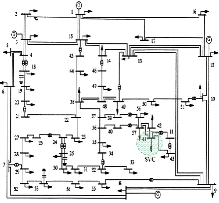
[image:5.595.314.543.70.254.2]This paper is presented in the concept of voltage stability of IEEE-57 bus system i.e. voltage & angle magnitude for Newton-Raphson power flow and SVC. SVC connected for IEEE-57 bus system in bus number-41.Then the voltage magnitude lies between 0.95-1.05 P.U.
[image:5.595.57.280.195.401.2]Fig 6: IEEE 57 bus System with SVC
[image:5.595.315.542.286.478.2]Fig 7: IEEE 57 bus System N-R power flow Voltage Profile
[image:5.595.53.276.440.644.2]Fig 8: IEEE 57 bus System N-R power flow Angle Profile
Fig 9: IEEE 57 bus System N-R power flow with SVC Voltage Profile
[image:5.595.316.541.525.711.2]Volume 72– No.5, May 2013
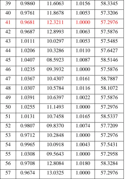
Table 1. MATLAB Output of IEEE-57 bus system voltage & angle magnitude of N-R Power flow SVC
BUS NO
V (P.U)
ANGLE (DEGREE)
Vsvc (P.U)
ANGLE (DEGRE)
1 1.0600 01.4067 1.0000 58.5876 2 1.0100 01.4067 1.0010 58.5876 3 0.9850 05.8615 1.0150 58.1552 4 0.9765 06.9149 1.0000 57.5876 5 0.9800 07.9008 1.0186 58.3607 6 0.9844 08.0353 1.0200 59.0147 7 1.0050 06.7305 1.0000 57.5876 8 0.9800 03.6456 1.0210 59.0147 9 0.9867 08.6756 1.0100 57.8687 10 0.9752 09.8352 1.0000 57.5876 11 1.0150 09.0009 1.0122 57.9938 12 0.9811 08.7864 1.0050 59.8741 13 0.9737 08.5663 1.0090 57.8089 14 0.9932 08.2373 0.9911 56.2116 15 1.0193 06.5271 1.0090 57.8089 16 1.0304 07.5757 1.0172 58.2735 17 1.0010 04.7206 1.0000 57.5876 18 0.9716 10.6655 1.0205 58.6137 19 0.9658 11.4934 1.0109 57.9009 20 1.0116 11.4429 1.0039 59.0077 21 1.0130 11.0236 1.0027 57.7446 22 1.0115 10.9344 1.0072 58.8276 23 1.0016 10.9695 1.0060 57.8492 24 1.0250 11.0921 1.0000 57.5876 25 0.9610 14.3136 1.0239 58.6630 26 0.9826 10.8536 0.9981 55.4670 27 0.9973 09.9570 1.0031 57.7632 28 1.0320 09.2087 1.0111 58.0007 29 1.0106 08.6627 1.0126 58.0032 30 0.9656 14.6520 1.0147 58.2832 31 0.9691 15.0383 1.0112 58.0020 32 0.9535 14.5732 1.0022 57.4245 33 0.9509 14.5954 1.0000 57.5876 34 0.9625 12.1091 1.0207 59.3709 35 0.9695 11.9452 1.0011 57.3483 36 0.9791 11.7686 1.0073 57.5345 37 0.9882 11.5585 1.0163 58.3766 38 1.0162 10.8433 1.0181 58.4807
39 0.9860 11.6063 1.0156 58.3345 40 0.9761 11.8678 1.0053 57.3206
41 0.9681 12.3211 1.0000 57.2976
42 0.9687 12.8993 1.0063 57.5876 43 1.0111 10.0297 1.0053 57.5485 44 1.0206 10.3286 1.0110 57.6427 45 1.0407 08.5923 1.0087 58.5146 46 1.0235 09.3932 1.0000 57.5876 47 1.0367 10.4307 1.0161 58.7887 48 1.0307 10.5784 1.0116 58.1072 49 1.0391 10.6397 1.0022 57.5876 50 1.0255 11.1493 1.0000 57.2976 51 1.0131 10.7458 1.0165 58.5337 52 0.9807 09.8370 1.0074 57.7209 53 0.9712 10.2848 1.0000 57.2976 54 0.9965 10.0918 1.0043 57.5431 55 1.0308 09.5643 1.0000 57.2958 56 0.9708 12.8084 1.0180 58.3284 57 0.9674 13.0325 1.0000 57.2976
7.
CONCLUSION
This paper consists of various aspects, regarding voltage and angle profile of Newton-Raphson power flow analysis for IEEE-57 bus system with and without SVC has been presented and the importance to maintain voltage profile and angle stability improvement has been discussed. There by the reactive power compensation was successfully done in the particular transmission whenever it is required. The power flow and the voltage profile in various transmission lines along with and without the placement of SVC in a specific transmission line is obtained in order to improve the system performance. Hence the themes of the paper to maintain voltage stability and angle enhancement have been successfully achieved with the incorporation of SVC.
8.
REFERENCES
[1] Jong, Su Yoon Soo, Yeol Kim Yong, Hak Kim Kyu, Chul Lee Chang, Keun Lee, “The analysis of STATCOM and SVC Cooperation Effect”, Transmission and Distribution Conference, Asia and pacific, 2009, pp1-5, Oct 2009.
[2] Acha, E, C.R. Fuerte-Esquivel, H. Ambriz-Perez and C. Angeles-Camacho, FACTS modeling and simulation in power networks. 1st Edn. John Wiley and Sons Inc., New York, ISBN: 978-0470852712, 2004.
[3] Xia Jiang Xinghao Fang Chow, J.H. Edris, A.-A. Uzunovic, E. Parisi, M. Hopkins, L. “A Novel Approach for Modeling Voltage-Sourced Converter-Based FACTS Controllers”, IEEE Transactions on Power Delivery, Vol 23(4), Oct 2008.
Volume 72– No.5, May 2013 Conference on Transmission and Distribution, 2004,
pp.976-980, Nov. 2004.
[5] Johnson, B.K. “How series and combined multiterminal controllers FACTS controllers function in an AC transmission system”, IEEE Power Engineering Society General Meeting, Vol.2, pp 1265-1267, June 2004. [6] Determination of Needed Facts Controller that Increase
Asset Utilization of Power System - L.A.S. Pilotto, W. W. Ping, Carvallho, Wey, Long and Edris -IEEE transaction on power delivery vol. 12 No. 1, January 1997.
[7] Reactive power compensation technologies: State of the art review. Juan Dixon, Senior member, IEEE, Luis morán, fellow, ieee,josérodríguez, senior member, IEEE, and Ricardo Domke
[8] IJAET, MAY 2012 ISSN: 2231-1963.Power flow model of static Var compensator and enhancement of voltage stability.H.BNagesh and P.S Puttaswamy.
[9] Power electronics in electric utilities: STATIC VAR COMPENSATORS BY: LASZLO GYUGYI.
[10]SVC MODELLING IN POWER SYSTEMS .M.Noroozian, ABBPowersystemsAB, Reactive Power Compensation Division, Vasteras, Sweden.
[11]IJRTE,Vol2,No.7,November 2009.Voltage Profile Improvement using SVC and Thyristor Controlled Voltage
Regulator(TCVR).M.ArunBhaskar,C.Subramani,M.Jagd eeshKumar,Dr.S.S.Dash,Dr.P.Chidambaram,SeniorLectu rer,Department of EEE,VEC,Chennai,India.
[12]Leonardo Journal of Sciences.ISSN 1583-0233(p.167-172).Issue 14, January-June 2009.Voltage Stability Improvement Using Static Var Compensator in Power Systems. Mark Ndubuka NWOHU.