2019 International Conference on Artificial Intelligence, Control and Automation Engineering (AICAE 2019) ISBN: 978-1-60595-643-5
Analysis and Calculation of Commutation Error for Sensorless
Brushless DC Motor
Jia-qi XIE
1,2, Yuan-feng HUANG
1,2and Hai-feng WANG
1,2,*1
Institute of Electrical Engineering, Chinese Academy of Sciences, Beijing 100190, China
2
University of Chinese Academy of Sciences, Beijing 100049, China
*Corresponding author
Keywords: Brushless DC Motor (BLDCM), Diode Freewheel Current, Filter Delay.
Abstract. The back EMF zero-cross detection method is widely used in sensorless position control. Since the back EMF cannot be measured, the terminal voltage is often used to approximate the back EMF. However, the terminal voltage is distorted caused by diode freewheeling current, filter delay and other factors, a phase difference will be generated between the terminal voltage and the back EMF. This phase difference makes position detection signal deviate from the best commutation time, even causes commutation failure in high speed or overload. This paper first analyzes the reasons of phase difference caused by diode freewheeling current and filter delay. Then, the relationship between phase difference angle, current and speed is presented through the simulation fitting method. Finally, simulation and experiment results prove the effectiveness of the calculation method. Moreover, from our study, the BLDCM can still achieve stable operation under sensorless control with different load torque and speed.
Introduction
The sensorless position control technology is the current research hotspot of brushless direct-current motor (BLDCM), among which the back EMF zero-cross detection method is the most widely used [1-4]. The ideal commutation point of the BLDC is delayed by 30°electrical angle of the back EMF zero-crossing point. Thus, the commutation time can be determined by detecting the back EMF zero-crossing point [5-8].
Since the back EMF of BLDCM cannot be directly measured, the terminal voltage is commonly used to approximate the back EMF. However, the terminal voltage is distorted by filter delay, signal calculation delay, diode freewheeling current and armature reaction. A phase difference will be generated between the terminal voltage and the back EMF. The phase difference makes position detection signal deviate from the best commutation time, which can reduce the electromagnetic torque, increase the torque ripple, and reduce the efficiency, even cause commutation failure in the high speed or overload [9].
[17] analyzed the reasons of ahead position signal caused by diode freewheeling current. A phase difference calculation method that is suitable for a low-pass filter with a phase lag of 90° is proposed, but the calculation formula is very complicated. Real time compensation in their method is computationally intensive and can consume too much processor resources. In currently, there are some limitations to the study of eliminating phase error, which cannot cover all the conditions from low speed to high speed and light load to overload. This paper proposes a phase difference calculation method that can satisfy most working conditions of the motor. Simulation and experiment results prove the effectiveness of this method. In summary, it has the following advantages:
1) The calculation process is simple and does not require much calculations; 2) The calculation result has high accuracy and small error;
3) It is simple to implement and consume slight system resources;
This paper firstly studies the BLDCM control system, analyzes the cause of the phase difference between the terminal voltage and the back EMF, and studies the influence of the filter delay and the diode freewheeling current in Section 1. The relationship between the phase different angle, current and speed is presented by the simulation method in Section 2. Compared with the formula method, the simulation method has a small amount of calculation and high accuracy on the controller. Finally the experimental results of the prototype validate that the method can give the leading commutation angle under different working conditions, thus ensuring the normal commutation of the motor under the working conditions with large changes in Section 3.
BLDCM Driver System Model and Commutation Strategy
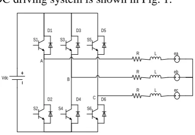
The equivalent circuit of BLDC driving system is shown in Fig. 1.
Vdc
R L ea
R
R L
L eb
ec S1
S2 S3
S4 S6
S5 D1
D2 D3
D4 D5
D6 A
B
[image:2.595.199.398.389.526.2]C
Figure 1. Equivalent circuit diagram of BLDCM.
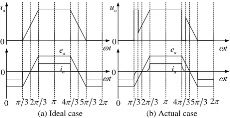
In ideal commutation, the back EMF is trapezoidal wave and the phase current is square wave. At the commutation time, the phase current of the turn-off phase drops to zero instantaneously, and then rises from zero to a certain value at the next commutation time. The phase of the terminal voltage waveform is the same as that of the back EMF waveform, as shown in Fig. 2(a). Therefore, the terminal voltage can be used to approximately replace the back EMF and control the motor commutation. But the motor winding is an inductance, the current cannot change abruptly during commutation, and the current will continue from the reverse parallel diode of the power transistor. The off-phase voltage will be clamped at zero until the current is reduced to zero, and the on-phase voltage will be clamped at the bus voltage Vdcto form a peak. Therefore, the waveform of the terminal
a
u ua
0 0 0 0 0 0 t t t t a
e ea
a
i ia
3
2 3 4 35 32 32 3 4 35 32
[image:3.595.178.416.74.196.2](a) Ideal case (b) Actual case
Figure 2. Voltage, back EMF and current waveforms during commutation.
Due to the influence of PWM carrier, the terminal voltage contains a lot of switching noise. It needs to be filtered to extract the fundamental component of the voltage. After the signal passes through the filter circuit, it will produce phase delay. Therefore, the actual measured terminal voltage phase will lag the back EMF.
According to the above analysis, the voltage vector diagram of the motor is shown in Fig. 3. Uf
is
the measured voltage vector after filtering, U
is the terminal voltage, e
is the back EMF and f is the lag angle caused by filter. is the ahead angle caused by diode freewheel current. Therefore, there is a phase difference between the measured terminal voltage and the back EMF, = f .
f
Uf
e R I U L j I X
Figure 3. Voltage phasor diagram of BLDCM. Phase Difference Calculation Method and Its Compensation
f
[image:3.595.197.402.537.616.2] is determined by the phase frequency response of the filter. The filter circuit used in this paper is shown in Fig. 4.
Figure 4. Third-order low-pass filter circuit. The phase frequency response formula of the filter is shown in Eq. 1.
2 2 3
1 1 2
2 3 2 3
( )
arctan arctan
1
f
C R R
R C
R R C C
. (1)
In Eq. 1, is the angular velocity (rad/s) of the motor rotor.
d U d U E U E U E U T U e U I U e 1
t t2t3 t4 t5t6 t7
e e 0 0 0
[image:4.595.236.356.73.225.2]270330 30 90 150 210 270
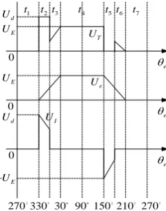
Figure 5. Voltage waveform and its decomposition diagram.
In an electric period, the voltage UT can be divided into six states, diode freewheeling current occurs in t2 and t5, in which the voltage UT is clamped to bus voltage Ud or 0, the voltage UI is 0 in the remaining states, in which the waveforms of UT and Ue are consistent.
When the load changes, Ue will remain unchanged, but UI will occur great changes. Under light load, the current is small, t2 and t5 are very short, UI causes only a weak influence, and can be ignored. Under heavy load, the current is large, the freewheeling time is long, the influence on the voltage UI is serious, and the phase advance angle cannot be ignored. The longer the freewheeling time, the larger the phase advance angle . Therefore, is related to the diode freewheeling time t, and the relation is shown in Eq. 2.
cos 30 = arctan sin 30 I E I u tu u t
. (2)
In Eq. 2, uE is the back EMF fundamental component, uI is clamping voltage fundamental component, and t is the freewheeling time of the diode, as shown in Eq. 3.
3 = 2 dc LI t
V E . (3) According to Eq. 1, Eq. 2, Eq. 3, the phase difference between measured terminal voltage and back EMF is related to current I and speed n, but real-time measurement and calculation of the phase difference will occupy DSP system resources and affect controller performance. Therefore, within the allowable error angle range, polynomial fitting is carried out on the relationship between phase difference, current and speed, and commutation control is implemented in the controller by looking up the table. In the process of solving the formula method, the parameters in Eq. 1, Eq. 2, Eq. 3 cannot be directly measured and need to be approximated, thus increasing the error. In order to simplify calculation and reduce error, based on actual motor parameters, BLDCM sensorless position control model is built in Matlab/Simulink as shown in Fig. 6. Motor parameters are shown in Table 1.
Table 1. Parameters of BLDCM.
Motor parameter Rating Motor parameter Rating Rated voltage 310(V) Rated current 5.4(A)
[image:4.595.137.459.662.736.2]Figure 6. Simulation model of BLDCM.
[image:5.595.148.448.265.349.2]Through simulation, the phase difference can be obtained when the motor is loaded with different loads at the rated speed as shown in Table 2.
Table 2. Phase difference corresponding to different load torque.
Load torque Tm (N•m)
Phase difference θ (°)
Load torque Tm (N•m)
Phase difference θ (°)
0 -45.12 4 -41.52
1 -44.64 5 -40.68
2 -43.2 6 -39.984
3 -42.48
The measured terminal voltage lags behind the back EMF, and with the increase of load, will gradually become larger, thus will decrease.
By fitting the simulation results, the relationship among phase difference, speed and current can be obtained as shown in Eq. 4. The image is shown in Fig. 7.
= f 2.61 0.02394n 0.909I
. (4)
Figure 7. Phase difference and fitting curve.
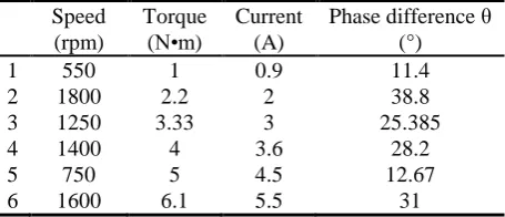
In order to verify the accuracy of the fitting result, arbitrarily select six points in Fig. 7, calculate the phase difference according to Eq. 4, and compensate the terminal voltage phase. The parameters of the selected six points are shown in Table 3. The waveforms of voltage Ufab after filtering, compensated voltage euab and the back EMF eab are shown in Fig. 8.
Table 3. Selected six verification points.
Speed (rpm)
Torque (N•m)
Current (A)
Phase difference θ (°)
1 550 1 0.9 11.4
2 1800 2.2 2 38.8
[image:5.595.192.403.447.568.2] [image:5.595.185.413.679.777.2]Time(s)
Point 1
Point 2
[image:6.595.195.410.73.292.2]Point 6 Point 5 Point 4 Point 3
Figure 8. Waveforms of eab, Ufab and euab of six verification points.
From Fig. 8, under different working conditions, the zero-crossing point of the compensated voltage euab and the zero-crossing point of the back EMF eab are coincident, indicating that the phase of the compensated voltage euab can always keep synchronization with the back EMF eab. The commutation signal calculated by the compensated voltage euab is consistent with the ideal commutation signal, and the error is very small. The sensorless position control of BLDCM can accurately track the commutation position, and is not affected by the change of speed and load, which verifies the correctness of the phase difference calculation method proposed in this paper.
Prototype Experiment and Verification
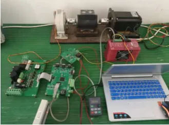
In order to verify the phase difference calculation method proposed in this paper, a BLDCM test platform is built using TMS320F2812. The motor parameters are shown in Table 1. The test platform is shown in Fig. 9.
Figure 9. BLDCM test platform.
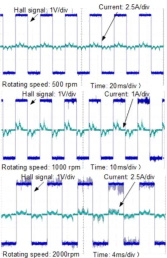
[image:6.595.215.380.491.613.2]Figure 10. Current and hall signals.
[image:7.595.210.385.425.598.2]When no-load, even if the speed changes, the turn-on time of current is basically the same as the signal jump time of hall sensor. It proves that the compensated terminal voltage signal calculated by the equation can control the correct commutation. When the speed is 1500rpm, measure the current and hall signals with no-load and with rated load, as showed in Fig. 11.
Figure 11. Current and hall signals with no-load and rated load.
Fig. 11 shows that when the motor runs at a fixed speed and the load changes, the turn-on time of the current is basically the same as the signal jump time of the hall sensor. It proves that commutation angle calculated by the equation mentioned above can make the motor commutate correctly of the sensorless position control.
Conclusion
Therefore, the simulation and the polynomial fitting method is used to calculate the phase difference. The experimental results of the prototype show that the method can give the leading commutation angle under different working conditions, thus ensuring the normal commutation of the motor under the working conditions with large changes. Meanwhile, there is no problem of complicated derivation and large calculation amount, which has certain guiding significance in engineering.
References
[1] Tan Jiancheng, Permanent Magnet Brushless DC Motor Technology, first ed., China Machine press, Beijing, 2011.
[2] Acarnley P P, Watson J F. Review of position-sensorless operation of brushless permanent-magnet machine, IEEE Trans. Ind. Electron. 53 (2006) 352-362.
[3] Shi Jian, Li Tiecai,Wang Xiaowei, et al. A Sensorless Control Method of Small Inductance Brushless DC Motors With Three-phase H-bridge Connection, Proceedings of the CSEE. 34(2014) 1905-1911.
[4] Lai Y, Lin Y. Novel back-EMF detection technique of brushless dc motor drives for wide range control without using current and position sensors, IEEE Trans. Power Electron. 23(2008) 934-940.
[5] Zhu Junjie, Su Mei, Chen Cheng, et al. Novel BEMF zero-crossing detecting method for brushless DC motor, Chinese Journal of Scientific Instrument. 34(2013) 441-447.
[6] Li Zicheng. The Research on Key Technologies for Sensorless Control of Brushless DC Motors. Ph.D Thesis, Huazhong University of Science and Technology, 2010, p.17-20.
[7] Jiang Q, Bi C, Huang R. A new phase-delay-free method to detect back EMF zero-crossing points for sensorless control of spindle motors, IEEE Trans. Magn. 41(2005) 2287-2294.
[8] Wang Kai. Study on third harmonic EMF-based sensorless high-speed BLDC motor. Ph.D Thesis, Zhejiang University, 2009, p.84-91.
[9] Jung D H, Ha I J. Low-cost sensorless control of brushless DC motors using a frequency-independent phase shifter, IEEE Trans. Power Electron. 15(2000) 744-752.
[10] Wu Xiaojing, Zhou Bo, Song Fei. A New Control Method to Correct Position Phase for Sensorless Brushless DC Motor, Transactions of China Electrotechnical Society. 24(2009) 54-59.
[11] Song Fei, Zhou Bo, Wu Xiaojing. Closed Loop Control Method to Correct Position Phase for Sensorless Brushless DC Motor, Proceedings of the CSEE. 29(2009) 52-57.
[12] Zhang Lie, Qu Wenlong, Lu Haifeng, et al. A Novel Sensorless Control System of Brushless DC Motors, Transactions of China Electrotechnical Society. 26(2006) 26-30.
[13] Shen Jianxin, Chen Yongxiao. Analysis of Shaft Position Detecting Error in a BLDC Motor with ‘Back-EMF Method, Transactions of China Electrotechnical Society. 01(1998) 11-15.
[14] Wei Kun, Ren Junjun, Zhang Zhongchao. Research on the scheme of sensing rotor position of BLDCM based on the third harmonic component, Proceedings of the CSEE. 05(2004) 167-171.
[15] Shen J X, Iwasaki S. Sensorless control of ultrahigh-speed PM brushless motor using PLL and third harmonic back-EMF, IEEE Trans. Ind. Electron. 53(2006) 421-428.
[16] Cheng Xi, Nie Xin. Influence and Compensation of Commutated Current Freewheeling for Sensorless Brushless DC Motor, Electronic Science & Technology. 04(2017) 4-11.