Skin and Motion Cues Incorporated Covariance Matrix
for Fast Hand Tracking System
Mohd Shahrimie Mohd Asaari
,
Shahrel Azmin Suandi
∗,
Bakhtiar Affendi Rosdi
Intelligent Biometric Group, School of Electrical and Electronic Engineering, Engineering Campus,
Universiti Sains Malaysia (USM), 14300, Nibong Tebal, Penang, Malaysia
∗Corresponding Author: [email protected]
Copyright c⃝2014 Horizon Research Publishing All rights reserved.
Abstract
Hand tracking is one of the essential elements in vision based hand gesture recognition system. The tracked hand image can provide a meaningful gesture for more natural ways of Human Computer Interaction (HCI) sys-tems. In this paper, we present a fast hand tracking method based on the fusion of skin and motion features incorporated covariance matrix. First, hand region is detected using a fusion of skin and motion cues, and a region of interest (ROI) is created around the detected region. During the tracking, skin and motion features are extracted around top, left and right corners of the ROI and hand displacement is measured using ROI based tracker. To increase the robustness, we incorporate a covariance matrix of the ROI window as a region descriptor to represent the target object. In the consecutive frames, we measure the distance descriptor covariance matrix (DDCM) between the target object and the covariance matrix extracted from new ROI position. When DDCM is not satisfying a certain acceptable threshold, ROI position is adjusted by shifting the ROI window around nearest neighbor to obtain a set of candidate regions. We assign a candidate region which has the smallest DDCM as the correct estimated ROI position. The experimental result shows that our approach can track the hand gesture under several real-live scenarios with a detection rate above 95% with the tracking speed at 42fps on average.Keywords
Hand Detection, Hand Tracking, Region of Interest, Hand Gesture, Covariance Matrix1
Introduction
Currently, vision based object tracking has become an im-portant task within the field of computer vision. The avail-ability of high quality and low-priced video cameras, and the increasing need for automated video analysis has gained a great interest in object tracking algorithms [16]. One of the pertinent applications of object tracking is in vision based hand gesture recognition systems. In vision based hand ges-ture, the detection and tracking of the human hands are the foundation steps of the recognition system, where hands must be localized in every image sequence. The effectiveness of hand tracking greatly depends on its ability to function
re-liably in real time so that an instant inter- action would be achievable. On the other hand, to guarantee more accessi-bility, such tracking system should not require user to wear special clothes or cumbersome devices such as colored mark-ers. Moreover, in vision based, hand tracking is a challenging task due to difficulty to deal with variations in its appearance mainly caused by shape and pose change, rapid and erratic motion, illumination changes and occlusion problem. There-fore, by solving these issues, it will directly enhance the per-formance of the whole gesture system [11].
scene is exposed to illumination effect and contain a large amount of changes. In [1], hand detection is achieved using a fusion of skin color and motion features. A rectangular ROI is then defined to represent the detected hand location. The hand tracking is achieved using ROI based tracker, which uti-lizes the distributions of skin and motion pixels which are ob-tained from the ROI edges. They managed to track the hand under cluttered environment with a promising detection rate at real-time speed, by assuming the difference between frame interval is relatively small and no unrelated skin colored ob-jects move close to the ROI.
In 2006, Porikli et al. [12] proposed a method to track non-rigid object using covariance matrix representation [14] and model update mechanism using a mean manifold. In their ap-proach, they represent the target object with a set of features as a covariance matrix and manage to capture the correlation of spatial and statistical properties between the same repre-sentations. At each consecutive frame, they search the whole image to find a candidate region that has a covariance ma-trix which is most similar to the target object. The model update mechanism effectively adapts the object deformations and appearance changes. Even though the covariance tracker efficiently detects the non-rigid objects, the tracking perfor-mance decreases when the background and target object has a very less color variation. Moreover, most of the compu-tational power in the covariance tracker is spent to compare the target model with the candidate regions from the whole image which makes the system hard to achieve a real time performance.
In this paper, we propose a real-time hand tracking sys-tem using the ROI based tracker based on the fusion of skin and motion features. In this approach, we advocate the effi-cient integration of region descriptor covariance matrix [14] into the ROI based tracking framework in order to gain a more robust tracker. We also introduce the temporal frame difference into the covariance feature mapping to reduce the tendency of fusing the background pixels into the region de-scriptor. By incorporating the covariance matrix, the ROI based tracker has a specific reference model of the object be-ing tracked. This is to efficiently reduce the driftbe-ing problem when the hand is moving fast, erratic, and when there are un-wanted skin colored objects move close to the ROI. In our proposed method, we shift the previous hand ROI position to the nearest neighborhood location based on previous detec-tion posidetec-tion to obtain a set of candidate regions rather than to search from the whole image. Therefore, we save a lot of the computational power used to compare the target model with the candidate regions. For complete flow of the hand gesture tracking system, we refer the readers to Fig.(1).
The remaining of this paper is organized as follow. In sec-tions 2 and 3, we describe the detail of the tracking algorithm. In section 4, we describe the detail experimental results to evaluate the robustness and the efficiency of the proposed al-gorithm. Finally we conclude the contribution of this paper and identify areas for future development in section 5.
2
Initialization Stage
2.1
Skin Segmentation
In this work, we extract skin pixels usingY CbCr pixels
distribution. Y CbCrcolor space is derived in such way that
the illumination component is concentrated only inY
com-Figure 1.Flow chart of the hand gesture tracking system.
ponent while color is contained inCb andCr chrominance
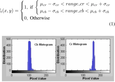
components. The illumination can vary significantly over the skin region under different lighting effect thus difficult to se-lect range of skin color values. Therefore, to reduce illumi-nation effect, only chrominance components are used to se-lect range of skin color value. Fig.(2) shows the histogram of Cb andCr components. Since the histograms are likely
similar to normal distributions, the mean and standard devia-tion are taken into account for skin segmentadevia-tion as shown in Eq.(1) where,µcbandµcr are overall mean andσcbandσcr
standard deviation of ofCbandCrcomponents respectively.
The result of skin regions segmentation,St(x, y)is depicted
in Fig.(3).
St(x, y) =
1, if
{
µcr−σcr < range cr < µcr+σcr
µcb−σcb< range cb < µcb+σcb
0, Otherwise
[image:2.595.326.527.51.392.2](1)
[image:2.595.316.553.605.774.2]Figure 3.Skin Color Regions Segmentation.
2.2
Motion Segmentation
When object moves in spatial space, motion information can be extracted by examining the local grey level change. To detect the moving object, the simplest technique is to use frame differencing method because it has great detec-tion speed. LetFt(x, y)be thetthRGB image sequence and F dt(x, y)is the frame difference betweentthand(t−1)th
frame defined in Eq.(2). The frame difference image is then converted to grey level image using Eq.(3), where RGB are the elements ofF dt(x, y). The binary image,F dbt(x, y)of
the frame difference is obtained using Eq.(4), whereT is a threshold value. In this procedure, the threshold value is ob-tained experimentally and determined asT = 0.05 ¯X, where
¯
Xis the average pixels value of grey level image. The result of motion segmentation is depicted in Fig.(4).
F dt(x, y) =|Ft(x, y)−Ft−1(x, y)| (2)
F dgt(x, y) = 0.299R+ 0.587G+ 0.114B (3)
F dbt(x, y) =
{
1, F dgt(x, y)÷255≥T
[image:3.595.55.269.382.676.2]0, Otherwise (4)
[image:3.595.353.540.637.736.2]Figure 4.Motion Segmentation.
Figure 5.Hand Region Extraction.
2.3
Defining Hand ROI
After segmenting the frames using skin and motion fea-tures, the hand region can be located by combining these two features using logical AND operator. By combining these two features, face regions and other skin colored objects that remains after skin segmentation are discarded. The combi-nation of skin and motion imageSMt(x, y), are defined in
Eq.(5) and Eq.(6), respectively, wherefm[M, N]is a median
andf[i, j]is a 3x3 masking window used to remove the un-wanted impulse noise pixels remained in theM ×N image. The hand ROI, which is defined as a rectangular bounding box around the binary imageSMt(x, y), can be obtained
us-ing Eq. (7), where[C]and[R]are vectors that contains hori-zontal and vertical coordinates extracted from white pixels of
SMt(x, y)binary image. The result of hand region
extrac-tion is depicted in Fig.(5).
SMt(x, y) = (St(x, y) &F dbt(x, y))∗fm[M, N] (5) fm[M, N] =median{f[i, j]} (6) ROIt(x, y) =rectangle(SMt(x, y),[m, n, w, h]) (7)
where, w = max[C]−min[C], h = max[R]−min[R],
m= min[C]andn= min[R]
3
Tracking Stage
3.1
ROI Based Tracker
Once the hand has been localized, the skin and motion pix-els available around the hand ROI are used as important in-formation to track the new hand location in the successive frame. Base on the information fromROIt(x, y)in Eq.(7),
the skin and motion pixels are extracted by scanning around top, left and right corners of the ROI as in the following equa-tions
rightt(i, j) =rectangle(SMt(x, y),[p, n,0.2w, h]) (8) lef tt(i, j) =rectangle(SMt(x, y),[q, n,0.2w, h]) (9) topt(i, j) =rectangle(SMt(x, y),[m, r, w,0.4h]) (10)
wherep=m−0.2w,q= max[C]andr=n−0.2h. In this work, the dimensional size of the abovementioned ROIs are determined empirically. The amount of white pixels available from each ROI can provide useful information to update new hand position, which can be obtained from the Eq. (11), (12) and (13).
sumright=
j
∑
j=1
i
∑
i=1
rightt(i, j) (11)
sumlef t= j
∑
j=1
i
∑
i=1
lef tt(i, j) (12)
sumtop=
j
∑
j=1
i
∑
i=1
topt(i, j) (13)
Table 1.ROI Based Tracking Algorithm.
If ( sumright>sumleft )
find the right displacement and shift the ROI to the right elseif ( sumleft>sumright)
find the left displacement and shift the ROI to the left else
keep the previous ROI column coordinate end
If ( sumtop>0 )% shift the ROI either to top or bottom If (the min row coordinate<half of thetopt(i, j)height)
find the top displacement and shift ROI to the top
elseIf (the min row coordinate>half of thetopt(i, j)height)
find the bottom displacement and shift ROI to the bottom end
else
keep the previous ROI row coordinate end
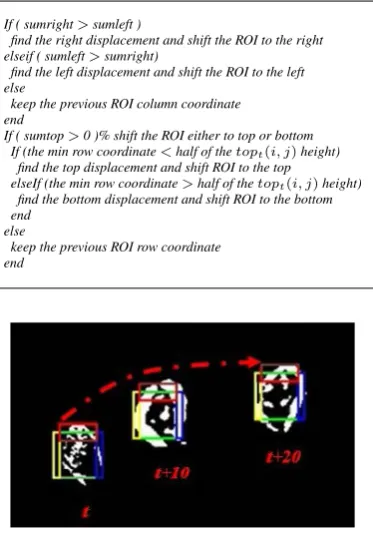
Figure 6.Illustration of ROI Based Tracking Algorithm from step intervalt
tot+ 20. Right, left and top scanning regions are illustrated in yellow, blue and red bounding box, respectively.
3.2
Hand Region Covariance Matrix
Tracking the hand using the raw pixel value from skin and motion information is not sufficient especially when hand is moving very fast or other skin region is moving rapidly near the hand ROI. As illustrated in Fig.(6), ROI Based tracking algorithm tracks the moving hand by only utilizing the infor-mation extracted near the edges of the moving region without considering the region inside the ROI that contains a lot of useful appearance attributes such as the intensity, color and frame difference values. To improve the ROI Based tracking algorithm, we incorporate a covariance matrix [14] of a set of features extracted from ROI window as a region descrip-tor to represent the target object. In the consecutive frame, we construct another covariance matrix corresponding to the new ROI position and compute the distance descriptor covari-ance matrix (DDCM) from the target object to verify the new ROI position, so that it always similar with the target object. LetRt(x, y)be theW ×H×ddimensional features image
extracted fromROIt(x, y)as a function of feature mapping, Φas illustrated in Eq. 14,
Rt(x, y) = Φ(ROIt(x, y)) (14)
where, the functionΦcan be any mapping such as intensity image, RGB color image, frame difference values, etc. We arrange the features vector which includes the spatial and ap-pearance attributes which directly relate the pixels coordinate as described in Eq.15
F(x,y)=
[
f1f2f3f4. . . . .fd]T (15) where, F(x,y) is the d-dimensional features vector inside
[image:4.595.86.273.72.340.2]Rt(x, y). In this work, we select 10 features (d= 10) where, f1andf2are the pixel locations inxandy,f3is the intensity image obtained from Eq.(3), f4, f5, f6 andf7 are the first
Table 2.Example of features vector arrangement if the ROI size is28×44.
f1 1 2 3 4 . . . 26 27 28
f2 1 1 1 1 . . . 44 44 44
[image:4.595.89.267.221.335.2]f3 170 184 176 181 . . . 52 39 24 f4 170 170 16 7 . . . 7 10 28 f5 170 174 186 181 . . . 4 16 18 f6 170 166 8 17 . . . 1 16 2 f7 170 174 186 181 . . . 0 4 6 f8 208 212 241 240 . . . 40 33 33 f9 188 192 201 200 . . . 29 31 31 f10 174 178 161 160 . . . 14 25 25 Table Note :
f1=x location,f2=y location,f3=I(x, y) f4=∂I(x,y)
∂x
,f5=∂I(x,y)
∂y
,f6=∂2I(x,y)
∂x2
,f7=∂2I(x,y)
∂y2
f8=R(x, y),f9=G(x, y),f10=B(x, y)
and second derivatives of the intensity image with respect to
xandy,f8,f9andf10are theRGBcolor values extracted fromROIt(x, y), respectively. The first and second
[image:4.595.321.554.438.538.2]deriva-tive images are calculated through the filters [-1 0 1]T and
[-1 2 -1]T respectively. Although the variance of the pixel
locations (x, y)is the same for all the regions of the same size, they are still important since the correlation with the other features are used at the non-diagonal entries of the co-variance matrix [14]. The detail arrangement for a sample of feature vectors extracted fromRt(x, y)region with28×44
window size and concatenated into rows vectors is depicted in Table 2.
From Table 2, consider that we have rows entries of f1 andf2, which are denoted as vectorsXandYrespectively, whereXandYare random variables, each with finite vari-ance, then the covariance of two random variables,XandY, can be mathematically represented in Eq. (17).
X=[x1 x2 x3 x4 . . . xn−1 xn
]T
Y=[y1 y2 y3 y4 . . . yn−1 yn
]T (16)
Cov(X,Y) = 1
n n
∑
i=1
[(xi−x)(y¯ i−y)]¯ (17)
where,x¯= 1n n
∑
i=1
xiandy¯= 1n n
∑
i=1
yi. This relationship can
be generalized as a multivariate situation to relate a set ofd -dimensional features insideW×H window size ofRt(x, y)
using a covariance matrix form as described in Eq. (18)
CovRt = 1 W H
W H∑ i=1
(fi−µRt)(fi−µRt)
T (18)
where,CovRtis thed×dcovariance matrix ofRt(x, y)and µRt is the mean vector corresponding to the features pointf
insideRt(x, y).
3.3
Distance Descriptor Covariance Matrix
In every consecutive frame, we construct another co-variance matrix corresponding to the new ROI position
Rt+1(x, y) and denote as CovRt+1. We compare the new
covariance matrix, CovRt+1 with the target covariance
ma-trixCovRt, by measuring the distance descriptor covariance
algorithms of generalized eigenvalues to measure the dissim-ilarity of two covariance matrixes as describe in Eq.(19)
DDCM(CovRt, CovRt+1) =
v u u t∑n
d=1
ln2λd(CovRt, CovRt+1)
(19) where, {λd(CovRt, CovRt+1)}d=1...n are the generalize
eigenvalues ofCovRt+1andCovRtwhich are obtained from
Eq.(20)
(CovRt)xd=λd(CovRt+1)xd (20)
where,{xd}d=1...nare the generalize eigenvectors. The ROI
position is adjusted when the DDCM is not satisfying for a certain threshold value, which can be obtained from a set of experiments. The examples of the DDCM measurement are illustrated in Fig.(7). To adjust the ROI position, we shift the ROI window around nearest neighbor to obtain a set of can-didate regions. At each cancan-didate regions, we compute its covariance matrix and its distance covariance matrix about the target object and select the region which has the small-est distance as the small-estimated new ROI position. Then, the covariance matrix is updated corresponding to the previous estimated selected candidate region. Fig.(8) shows the con-dition where the ROI position of the successive frame needs to be adjusted when the distance covariance matrix from the target object is exceeding the threshold value,TDDCM. The
[image:5.595.309.527.53.408.2]red bounding box in Fig.(8b) represents the neighboring re-gion to obtain a set of candidate rere-gions to estimate the cor-rect ROI position based on the smallest distance covariance matrix.
[image:5.595.63.263.428.484.2]Figure 7.DDCM measure for a set of difference ROI region.
Figure 8. Situation where ROI position is adjusted when the covariance matrix distance is not satisfyingTDDCM value. (a) ROI position set as target object, (b) ROI position needs to be adjusted. The red bounding box represents nearest neighbor to obtain candidate region.
4
Result And Discussion
The experiments were executed using MATLAB 7 which performed on Intel Core Duo at 2GB RAM, under Windows 7 operating system. The frames sequences were captured at 30fps using low price USB camera with a resolution of
352×288. The camera focused mainly upper part of the gesturer body and the actor was not restricted to wear either short or long sleeved clothing. During the initialization, the
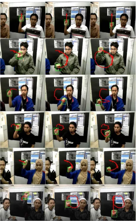
Figure 9.From top to bottom; Gestures performed by six different individ-uals for trajectory “1”, “0”, “2”, “S”, “C” and “9”.
actor makes significant movement using his hand and dur-ing this process, other part of the body is allowed to move in small scale. Our experiments only consider on tracking one hand because our main focus is to extract the hand mo-tion trajectory which will be used as trajectory based hand gesture recognition system.
We prepared the databases in two groups, where the first group is used to evaluate tracking performance for trajectory based gestures and the second group is to evaluate tracking performance under several real live scenarios. We consider that the estimated hand position is accurate if it is fall within
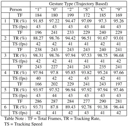
9×9 neighborhood of the ground truth target object cen-tre position, where the tracking rate is defined as the ratio of successful estimated frames over total frames. Since each in-dividual has different ways of performing the same gestures and there are also variations in skin color, we performed ex-periment that was carried out by six different individuals on six types of gesture using the databases from the first group. The results are listed in Table 3, where the average tracking rate is 95.43 % with the tracking speed at 42fps on average. The samples tracking results are illustrated in Fig.(9).
[image:5.595.55.270.531.624.2]Table 3.Hand gesture tracking rate of six difference person for six types of gesture.
Gesture Type (Trajectory Based) Person “1” “0” “2” “S” “C” “9”
TF 184 180 199 172 185 169 1 TR (%) 91.85 97.22 94.47 97.09 97.3 95.26
TS (fps) 43 43 43 43 44 43 TF 196 241 233 229 240 229 2 TR (%) 88.27 98.76 94.42 96.51 91.67 93.01
TS (fps) 42 42 41 41 42 41 TF 238 243 243 243 240 241 3 TR (%) 98.31 98.76 97.94 97.53 98.75 96.68
TS (fps) 42 42 41 41 41 42 TF 243 227 241 243 235 241 4 TR (%) 97.94 97.8 95.85 93.82 95.24 97.66
TS (fps) 40 42 42 43 42 41 TF 166 202 229 241 243 197 5 TR (%) 93.97 97.52 96.94 97.92 97.94 97.46
TS (fps) 43 44 43 43 43 43 TF 286 287 284 277 290 281 6 TR (%) 93.71 87.8 89.43 92.78 91.38 96.44
[image:6.595.69.288.80.292.2]TS (fps) 42 41 42 43 41 42 Table Note : TF = Total Frames, TR = Tracking Rate,
TS = Tracking Speed
is expected because in our tracking procedures, we use the fusions of skin and motion features in ROI Based tracking algorithm which is able to discard the unrelated skin colored object that remains in the image.
In addition to this experiment, we tested the proposed algo-rithm in handling the situation when left hand moved rapidly near the ROI and it occluded with right hand (Scene B). In this case, the right hand is the object of interest. When both of the moving hands exhibit both motion and color features, the ROI Based tracking intents to drift to the wrong position as it does not have a significant reference model of the ob-ject being tracked. By incorporating the covariance matrix to represent the target object, the occlusion between both hands was successfully absorbed to prevent the hand ROI to drift to the wrong position as illustrated in Fig.(11). Since the mov-ing hand can undergo non-rigid transformation, the target co-variance matrix is updated in every step interval to adapt to this situation. We observed that the covariance update mech-anism has improved the ROI Based algorithm to track the non-rigid hand shapes and appearances (Scene C) as shown in Fig.(12). The proposed method also does not make any assumption on the motion of the tracked object. Therefore, it helps to improve the tracking rate by reducing the drifting problems during unpredictable hand motion. As shown in Fig.(13), the proposed tracking algorithm has the ability to solve the tracking complexity when the hand is moving fast and rapidly changed its direction (Scene D). The covariance matrix also has an advantage property, in which it is invariant to the mean changes such as identical shifting of color values as described in [12]. As such, it enhances the tracking abil-ity when the hand moves under different illumination effect (Scene E) as illustrated in Fig.(14).
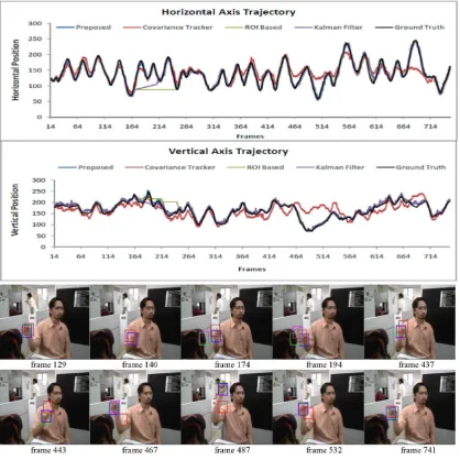
As a qualitative benchmark, we analyzed the performance of our proposed algorithm by comparing with Covariance tracker [12], Kalman Filter based tracker [2] and ROI based tracker [1]. We tested these three algorithms on image se-quence of Scene F as shown in Fig.(15). As illustrated from trajectory plot, in the case when the hand moves fast and er-ratically changed direction, the ROI based tracker easily fails it tracking state. On the other hand, the Kalman Filter based tracker provides a very smooth tracking trajectory, but there
Table 4.Hand tracking under real live scenarios.
Scene TF TR (%) TS (fps)
Scene A: Moving under cluttered environment 219 97.72 42 Scene B: Occlusion with other moving skin regions 369 97.28 42 Scene C: Rapidly change shape and appearance 240 97.23 43 Scene D: Rapidly change speed and direction 292 94.88 41 Scene E: Moving under different illumination effect 292 94.63 42 Scene F: Moving fast, rapidly change direction and
occlusion with face region 292 88.01 42 Scene G: Long video sequence under complex
environment 737 95.93 42
Table Note : TF = Total Frames, TR = Tracking Rate, TS = Tracking Speed
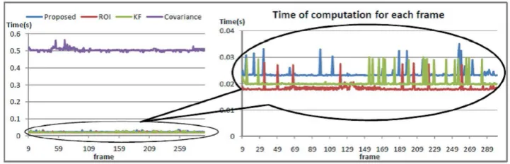
are drifting time occur when the hand rapidly changed its di-rection, therefore the tracking failed at this point. This is ex-pected because it was learnt that the Kalman Filter is difficult to deal with non-linear stochastic process estimation. In the case when the hand occluded with skin color regions, the tar-get model in the Covariance tracker tends to resemble with background pixels. When this situation occurs, the model update strategy proposed in [12] has a tendency to contami-nate with the unrelated background pixels which hampers a correct detection. In our procedures, the occlusion problem is addressed by utilizing the motion features in ROI based tracker to guide the covariance matrix to search a candidate regions based on previous ROI location, thus reducing the false detection. Although we observed that the Covariance tracker provides a close comparable tracking performance with our proposed method, it is far from real time implemen-tation because it is high compuimplemen-tational cost as compared to other algorithms as depicted in Fig.(16) because most com-putational power is used to search the candidate regions from the whole image. Finally, we tested our procedure on a long video sequence captured under complex environment (Scene G) with the trial duration more than 25 seconds to evaluate the long term stability. The trajectory plot and sample of the tracking images are illustrated in Fig.(17). From the trajec-tory plot, we observed that the proposed procedure gives the best result as compared to others methods.
[image:6.595.318.557.555.626.2]Figure 10.Hand motion tracking performed on Scene A
[image:6.595.315.558.695.770.2]Figure 12.Hand motion tracking performed on Scene C
Figure 13.Hand motion tracking performed on Scene D
Figure 14.Hand motion tracking performed on Scene E
5
Conclusion and Future
Develop-ment
[image:7.595.45.289.271.348.2]Figure 15.Trajectory plot and sample tracking results of proposed algorithm (blue rectangle), Covariance tracker (red rectangle), ROI based tracker (green rectangle) and Kalman Filter based tracker (purple rectangle) performed on Scene F.
[image:8.595.123.484.624.740.2]Acknowledgements
This work was supported by the USM Research University - Postgraduate Research Grant Scheme (RU-PRGS), (1001/PELECT/8034030) and the USM Postgraduate Incentive Grant, (1001/PELECT/8021023).
REFERENCES
[1] Asaari MSM, Suandi SA (2010) Fusion of motion and color cue for hand detection and tracking. World Engineering Congress pp 240–245
[2] Binh N, Shuichi E, Ejima T (2005) Real time hand tracking and gesture recognition system. International Conference on Graphic,Vision and Image Processing pp 111–115
[3] Chen F, Fu C, Huang C (2003) Hand gesture recognition using a real-time tracking method and hidden markov models. Image Vision Computing 21(8):745–758
[4] Comaniciu D, Ramesh V, Meer P (2004) Real-time tracking of non-rigid objects using mean shift. IEEE Conference on Computer Vision and Pattern Recognition pp 142–149
[5] Elmezain M, Al-Hamadi A, Niese R, Michaelis B (2010) A robust method for hand tracking using mean-shift algorithm and kalman filter in stereo color image sequences. International Journal of Information Technology 6(1):24–28
[6] Forstner W, Moonen B (1999) A metric for covariance matrices. Technical Report, Dept. of Geodesy and Geoinformat-ics, Stuttgart University
[7] Hee S, Gregorij K, Ruzena B (2008) Hand tracking and motion detection from the sequence of stereo color image frames. International Conference on Industrial Technology pp 1–6
[8] Imagawa K, Lu S, Igi S (1998) Color based hands tracking system for sign language recognition. International Confer-ence on Face and Gesture Recognition pp 462–467
[9] Isard M, Blake A (1998) Conditional density propagation for visual tracking. International Journal of Computer Vision 29(1):5–28
[10] Koh E, Won J, Bae C (2009) On-premise skin color modeing method for vision-based hand tracking. International Symposium on Consumer Electronics pp 908–909
[11] McAllister G, McKennan S, Ricketts I (2002) Hand tracking for behavior understanding. Image and Vision Computing 20(12):827–840
[12] Porikli F, Tuzel O, Meer P (2006) Covariance tracking using model update based on means on riemannian manifolds. IEEE Conference on Computer Vision and Pattern Recognition pp 728–735
[13] Shan C, Tan T, Wei Y (2007) Real-time hand tracking using a mean shift embedded particle filter. Pattern Recognition 40(7):1958–1970
[14] Tuzel O, Porikli F, Meer P (2006) Region covariance: A fast descriptor for detection and classification. European Conference on Computer Vision pp 589–600
[15] Utsumi A, Tetsutani N, Igi S (2002) Hand detection and tracking using pixel value distribution model for multiple-camera-based gesture interactions. Conference on Knowledge Media Networking pp 31–36
[16] Yilmaz A, Javed O, Shah M (2006) Object tracking: A survey. Acm Computing Surveys (CSUR) 38(4):13
[17] Zhai H, Wu X, Han H (2005) Research of a real time hand tracking algorithm. Internatonal Conference on Neural Networks and Brain pp 1233–1235