ISSN: 2278 – 7798
International Journal of Science, Engineering and Technology Research (IJSETR) Volume 5, Issue 5, May 2016Implementation of CCSDS Recommended Standard
for
Image DC Compression
Sonika Gupta
Post Graduate Student of Department of Embedded System Engineering G.H. Patel College Of Engineering and Technology
Gujarat Technological University Vallabh Vidyanagar, India
Abstract - Image compression is an important requirement of imaging payloads on Earth Observation satellites. For satellite image compression, the Consultative Committee for Space Data Systems (CCSDS) had proposed an image compression standard which is most widely implemented in hardware. This compression consists of a two dimensional discrete wavelet transform of the image, followed by bit-plane encoding of the transformed data. Bit Plane encoding comprises of DC coding and AC coding. This paper presents approach towards implementation of DC Coding. Some simulation results using MATLAB tool, and few modules implemented on Hardware are given in this paper.
Index Terms –CCSDS, DC coding, BPE, gaggle, Xilinx Virtex-5, block, segment.
I. INTRODUCTION
Image compression is one of key technologies for imaging instruments. It is an important issue in the communication between spacecraft and ground. The main objective of image compression is to remove most of the redundancies in the data and to encode the information in the least number of bits. The approach for data compression is believed to be the solution to the “Bandwidth Versus Data Volume” dilemma.
A. Types of Compression
1) Lossy Compression: This compression technique
reduces an image file by permanently eliminating certain information, especially redundant information. When the file is uncompressed, only a part of the original information is still there (although the user may not notice it).
2) Lossless Compression: Every single bit of data that
was originally in the file remains after the file is uncompressed. All of the information is completely restored. The original data can be reproduced exactly.
B. Types of DC Compression
1) DCT-Based Compression: Discrete cosine transform (DCT) is for converting a signal into elementary frequency components. DCT-based image compression relies
Geetali Saha
FacultyDepartment of Electronics and Communication G.H. Patel College Of Engineering and Technology
Gujarat Technological University Vallabh Vidyanagar, India
on two techniques to reduce the data required to represent the image. The first is quantization of the images DCT coefficients; the second is entropy coding of the quantized coefficients. Quantization is the process of reducing the number of bits needed to represent it. Entropy coding is a technique for representing the quantized data as compactly as possible.
2) Wavelet-Based Compression:
It comprises of lossy and lossless image compression. There are several methods of lossy compression: EZW (embedded zero tree wavelet) algorithm, SPIHT (set partitioning in hierarchical trees) algorithm, WDR (wavelet difference reduction) algorithm, and ASWDR (adaptively scanned wavelet difference reduction) algorithm[2]. Basic algorithm is
to digitize the source image into a signal s, which is a string of numbers. Decompose the signal into a sequence of wavelet coefficients w. Threshold to modify the wavelet coefficients from w to another sequence w'. Quantize to convert w' to a sequence q, then entropy code to compress q into sequence e.
II. CCSDS STANDARD
A. Overview
This Recommended Standard defines a particular payload image data compression algorithm that has wide spread applicability to many types of instruments. This Recommended Standard does not attempt to explain the theory underlying the operation of the algorithm.
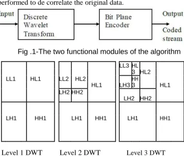
The algorithm consists of two functional modules as depicted in Figure 1. Discrete Wavelet Transform (DWT) is for de-correlation, and a Bit-Plane-Encoder (BPE) used to encode this de-correlated data[1].
B. Discrete Wavelet Transform
Wavelet transforms continuous or discrete time domain signals into a time-frequency domain signal. A DWT convolves a signal against certain specific wavelet filter coefficients, resulting in compression of original signal. Decompression can be done via IDWT by convolving the com pressed signal against an inverted order of original wavelet filter coefficients[1].Discrete Wavelet Transform(DWT) is
ISSN: 2278 – 7798
International Journal of Science, Engineering and Technology Research (IJSETR) Volume 5, Issue 5, May 2016performed to de correlate the original data.
Fig .1-The two functional modules of the algorithm
LL3 HL 3 HL2 LL1 HL1 LL2 HL2 HH HL1 LH3 3 HL1 LH2 HH2 LH2 HH2
LH1 HH1 LH1 HH1 LH1 HH1
Level 1 DWT Level 2 DWT Level 3 DWT Fig. 2-Three Level 2-D DWT decomposition of an image
C. Bit Plane Encoder
The wavelet transformed coefficients of an original image is reorganized into blocks where each block comprises of 64 coefficients. A block comprises of coefficients from all the sub bands generated by DWT. The top most left coefficient is DC coefficient which is single in each block and it is in LL3 sub band. The rest are called AC coefficients, which are taken from other sub bands as hierarchical structure given by DWT. Bit Plane encoding is categorized into DC coding and AC coding. Due to different nature of DC and AC coefficients, they are encoded with different techniques [3].
BPE gives more importance to the DC coefficients since most of information is contained in these coefficients. Resulting sub bands after DWT are stored in DWT memory. Once all ten sub bands are available, the DC coefficients are read by DC coder and then rice coding is carried out on quantized samples of DC coefficient. This is followed by AC coding. AC coding is done in four stages (1 to 4) as per standard given[1].
III. DC CODING
A. Overview
The initial coding of DC coefficients in a segment is performed in two steps
.
First step is encoding of quantized DC coefficient using Rice Coding described in next section. Second step is to encode additional bits of DC coefficient, when . The remainingbits of DC coefficient of a segment are encoded in stage0 of the Bit Plane Encoding.
The amount of quantization of DC coefficients performed in coding step shall be determined by the dynamic range of the AC and DC coefficients in a segment via the integer parameter
as in Table 1.
Rice Coder is a variable length coder and output bit stream is packed into 8 bits before writing it into memory. Refinement bits are also concatenated when writing into memory. Serial approach for coding and packing can be followed because there is only one DC coefficient in a block of 64 coefficients. The first quantized DC coefficient for every sequence of S consecutive coefficients, referred to as a
reference sample, shall be written to the encoded bit stream
directly (i.e., without any further processing or encoding). Table.1: DC Coefficient Quantization
DC and AC q' value Remark
Dynamic Range DC dynamic range is very small; no quantization is performed-all DC coefficient information is encoded in this step. DC dynamic range is close to half the AC dynamic range: the 3
MSBs of the DC coefficients are differentially coded. DC dynamic range is much higher than half
the AC dynamic range: the 10 MSBs of the DC coefficients are differentially coded. otherwise DC dynamic range is
moderately higher than half the AC dynamic range: the
DC coefficient bits exceeding half the AC
dynamic range are differentially coded.
B. Algorithm
DC coefficients are represented using two‟s- complement representations. Let denote the DC coefficient in a segment. Then the number of bits required to represent in two‟s-complement is given in equation.
, if
, if
1373
ISSN: 2278 – 7798
International Journal of Science, Engineering and Technology Research (IJSETR) Volume 5, Issue 5, May 2016Where is the maximum of this value over all DC coefficients in the segment. Similarly is calculated for AC coefficients. The first step, quantization of DC coefficient, is done where DC quantization factor is defined as given by the equation.
where is used to indicate the number of LSBs in each coefficient of the sub band LL3 that are necessarily zero as a result of sub band scaling operation[1].
The value of indicates the number of LSBs in each DC coefficient that need not to be encoded in the quantized DC coefficient values. For a given sequence of DC coefficients { : =0,…, S -1} in a segment, the quantized coefficient
is given in equation.
Next find the number of bits (N) needed to represent each quantized DC coefficient by given equation.
When N is 1, each quantized DC coefficient consists of a single bit. Otherwise N>1 and the quantized DC coefficients in a segment, encoded with procedure explained here. The first quantized DC coefficient for every sequence of S consecutive coefficients, referred to as a reference sample, shall be written to the encoded bit stream directly (i.e., without any further processing or encoding).
For the remaining S–1 DC coefficients, the difference between successive quantized coefficient values (taken in raster scan order) shall be encoded.
if if
, otherwise otherwise where
and ,
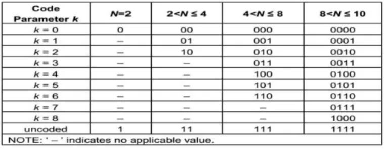
Each gaggle contains up to 16 mapped quantized coefficient . (a) The first gaggle contains 15 values of (the first quantized DC coefficient is coded directly as a reference sample); (b) The remaining gaggles each contain 16 values of , with the possible exception of the last gaggle, which may have fewer; (c) If S is not a multiple of 16, then the last gaggle contains J values of , where J equals S mod 16. The value of in each gaggle is encoded using one of several code options as in Table.2, ranging from uncoded(each is encoded using the conventional N-bit unsigned binary integer representation) to coded via one of the several variable-length codes parameterized by k; k>0 & k ϵ Z.
The code option selected for the gaggle shall be indicated at the start of the coded quantized DC coefficients in the gaggle using the appropriate code option identifier selected[5] as
shown in Fig. 3 and Fig. 4.
When the uncoded option is selected, the coded gaggle is fixed in length, consisting of the option ID field, optionally followed by an N-bit reference sample.
Otherwise, given code parameter k, the variable-length codeword for has two parts. The first part shall consist of
zeros followed by a 1, where . The second part shall consist of the k LSBs of the binary representation of . Select the optimum value of k for each gaggle (i.e., select the value of „k‟ that minimizes the number of encoded bits)
Table. 2: Code Option Identifier
Coded Data Format for a Gaggle when uncoded Option is selected
Fig .3 Coded Data Format for a Gaggle
Coded Data Format for a Gaggle When a Coding Option is selected
Fig .4 Gaggle in segment
C. VHDL Implementation
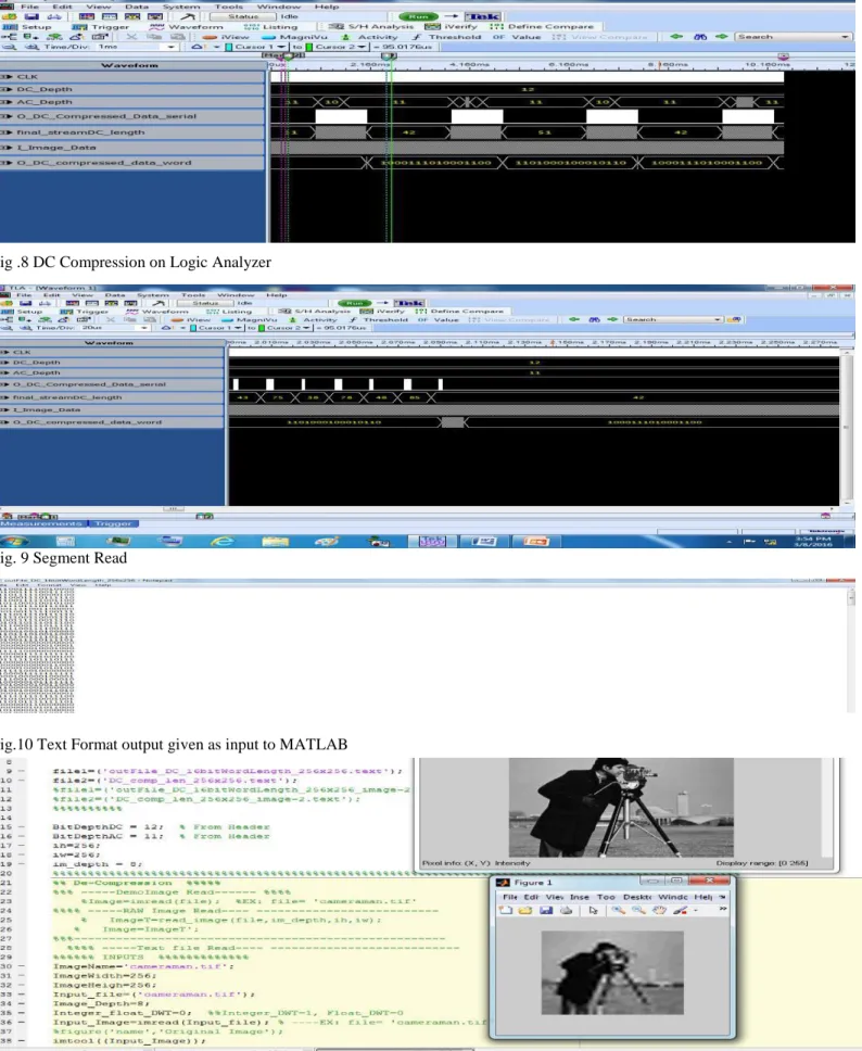
DC coding is implemented in VHDL and output is checked on computer using MATLAB. Fig. 6 to 11 shows the sequential flow of implementation results
ISSN: 2278 – 7798
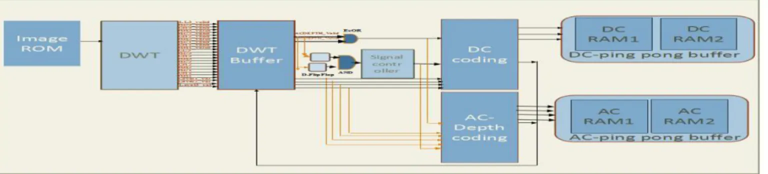
International Journal of Science, Engineering and Technology Research (IJSETR) Volume 5, Issue 5, May 2016Fig.5 BLOCK DIAGRAM
IV. RESULTS
Fig .8 DC Compression on Logic Analyzer
Fig .6 VHDL Results of Top module
Fig .7 MATLAB result for DC Coding
1375 All Rights Reserved © 2016 IJSETR
ISSN: 2278 – 7798
International Journal of Science, Engineering and Technology Research (IJSETR) Volume 5, Issue 5, May 2016Fig .8 DC Compression on Logic Analyzer
Fig. 9 Segment Read
Fig.10 Text Format output given as input to MATLAB
Fig.11 Compressed Image checked on MATLAB
ISSN: 2278 – 7798
International Journal of Science, Engineering and Technology Research (IJSETR) Volume 5, Issue 5, May 2016V. CONCLUSION This paper describes in brief the CCSDS Recommended Image
Data Compression Technique for space application taken under ISRO Project. DC Compression coding is VHDL implemented on Xilinx Virtex-5 FPGA Board[4] output is seen on Tektronix
Logic analyzer and the decompressed image is checked with MATLAB Tool . This work of compression gives compressed image of less quality, sharpness of image is somewhat reduced and artifacts are introduced. In future scope of this work, quality enhancement of image compression can be done by using AC coding i.e.; bit plane encoding method.
REFERENCE
[1] Image Data Compression, Recommendation for Space Data Systems Standards, CCSDS 122.0-B-1, Blue Book, Issue 1. Washington DC CCSDS, November, 2005, available from www.ccsds.org.
[2] Image Data Compression, Information Report for Space Data Systems Standards, CCSDS 120.1-G-1, Green Book, Issue I. Washington DC CCSDS, June 2007, available from www.ccsds.org.
[3] Li Li, Gang Zhou, Bjorn Fiethe, Harald Michalik, and Bjorn Osterloh. ”Efficient implementation of the CCSDS 122.0-B-1 compression standard o a space-qualified field programmable gate array”. In: Journal of Applied Remote Sensing 7.1 (2013), pp. 074595-074595.
[4] Xilinx, Inc. Radiation-Hardened, Space- Grade Virtex-5QV Device Overview.2011.
[5] Pen-Shu Yeh, Philippe Armbruster, Aaron Kiely, Bart Masschelein, Gilles Moury, Christoph Schaefer. Carole Thiebaut. “ The New CCSDS Image Data Compression Recommendation” Proc. of the IEEE 2005 Aerospace Conference. Big Sky. Montana, March 2005.
[6] Image Data Compression, Recommendation for Space Data Systems Standards, CCSDS 122.0-B-1, Blue Book, Issue 1. Washington DC CCSDS, November, 2005, available from www.ccsds.org.
[7] Image Data Compression, Information Report for Space Data Systems Standards, CCSDS 120.1-G-1, Green Book, Issue I. Washington DC CCSDS, June 2007, available from www.ccsds.org.
[8] Li Li, Gang Zhou, Bjorn Fiethe, Harald Michalik, and Bjorn Osterloh. ”Efficient implementation of the CCSDS 122.0-B-1 compression standard o a space-qualified field programmable gate array”. In: Journal of Applied Remote Sensing 7.1 (2013), pp. 074595-074595.
[9] Xilinx, Inc. Radiation-Hardened, Space- Grade Virtex-5QV Device Overview.2011.
[10] Pen-Shu Yeh, Philippe Armbruster, Aaron Kiely, Bart Masschelein, Gilles Moury, Christoph Schaefer. Carole Thiebaut. “ The New CCSDS Image Data Compression Recommendation” Proc. of the IEEE 2005 Aerospace Conference. Big Sky. Montana, March 2005.
[11] Image Data Compression, Recommendation for Space Data Systems Standards, CCSDS 122.0-B-1, Blue Book, Issue 1. Washington DC CCSDS, November, 2005, available from www.ccsds.org.
[12] Image Data Compression, Information Report for Space Data Systems Standards, CCSDS 120.1-G-1, Green Book, Issue I. Washington DC CCSDS, June 2007, available from www.ccsds.org.
[13] Li Li, Gang Zhou, Bjorn Fiethe, Harald Michalik, and Bjorn Osterloh. ”Efficient implementation of the CCSDS 122.0-B-1 compression standard o a space-qualified field programmable gate array”. In: Journal of Applied Remote Sensing 7.1 (2013), pp. 074595-074595.
[14] Xilinx, Inc. Radiation-Hardened, Space- Grade Virtex-5QV Device Overview.2011.
[15] Pen-Shu Yeh, Philippe Armbruster, Aaron Kiely, Bart Masschelein, Gilles Moury, Christoph Schaefer. Carole Thiebaut. “ The New CCSDS Image Data Compression Recommendation” Proc. of the IEEE 2005 Aerospace Conference. Big Sky. Montana, March 2005.