An Organic Vortex Laser
Daan Stellinga†1, Monika E. Pietrzyk†2, James M. E. Glackin2, Yue Wang1, Ashu K. Bansal2, Graham A. Turnbull2, Kishan Dholakia2, Ifor D. W. Samuel*2,
and Thomas F. Krauss*1
1
Department of Physics, University of York, Heslington, York, YO10 5DD, UK
2
Organic Semiconductor Centre, SUPA, School of Physics and Astronomy, University of St Andrews, North Haugh, St Andrews, KY16 9SS, UK
Abstract: Optical vortex beams are at the heart of a number of novel research directions, both as carriers of information and for the investigation of optical activity and chiral molecules. Optical vortex beams are beams of light with a helical wavefront and associated orbital angular momentum. They are typically generated using bulk optics methods or by a passive element such as a forked grating or a metasurface to imprint the required phase distribution onto an incident beam. Since many applications benefit from further miniaturisation, a more integrated yet scalable method is highly desirable. Here, we demonstrate the generation of an azimuthally polarised vortex beam directly by an organic semiconductor laser that meets these requirements. The organic vortex laser uses a spiral grating as a feedback element that gives control over phase, handedness and degree of helicity of the emitted beam. We demonstrate vortex beams up to an azimuthal index l = 3 that can be readily multiplexed into an array configuration.
Keywords: Spiral grating, organic semiconductor, OAM, vortex beam, vector beam.
Optical vortex beams are beams whose phase rotates azimuthally around their optical axis, characterised by a phase singularity with vanishing intensity of light at the centre. The azimuthal index or topological charge of a vortex beam l counts the number of 2π phase shifts that occur in one revolution around the singularity, which corresponds to an orbital angular momentum of hl/2π carried by the beam. Vortex beams with different index l are mutually orthogonal and can therefore be multiplexed, which means they can be used as information carriers1. This scope for multiplexing is particularly attractive for 3D holographic imaging, which is a very topical area of research.2,3 Realising vortex beams in active organic materials, as demonstrated here, is a further advantageous feature for imaging applications given the growth of organic light-emitting diodes (OLEDs) in mobile phone and television displays4. Another interesting property of vortex beams is their ability to exert torque on small objects, including chiral molecules, which has potential applications in the development of molecular machines or light-activated drugs.5,6 It has also been shown that vortex beams can be used to achieve optical sorting of chiral objects, such as liquid crystal microspheres.7 All of these examples, especially the 3D display application, would benefit from realising the vortex beams as active light emitters that can be miniaturised, integrated into a small footprint package and arranged as arrays. Some of these requirements can be met by the recent successful implementations of metallic8 or dielectric9 metasurfaces as external ultra-thin vortex generators, yet an even better and more compact solution is the direct generation of optical vortices in micro-sized lasers, i.e. as active materials. In this respect, we note the experimental demonstration of a compact III-V semiconductor laser10 which, however, has only 3
demonstrated operation in the infra-red and for an azimuthal order of l = 1. Other methods of direct emission of vortex beams exist, but these cannot generally be scaled down to the microscale,11 or have not yet been experimentally demonstrated.12
Here, we demonstrate the direct generation of optical vortex beams in the visible for azimuthal orders up to l = 3. Our vertically emitting distributed feedback organic
semiconductor laser emits around λ = 540 nm with a narrow linewidth of ∆λ ~ 0.1 nm. The feedback for the organic laser is provided by a phase-controlled grating, where the local phase is determined by a lateral shift of the grating elements with respect to the unit cell.13,14 In order to achieve the desired azimuthally-varying phase control, a phase shift of 2π must be achieved around the beam, whilst simultaneously applying feedback. We show that this can be achieved by a grating consisting of an Archimedean spiral. By designing higher order spirals, the design allows us to directly control the angular momentum and the azimuthal order of the emitted beam, and generate beams with desired degrees of vorticity. A secondary effect of the spiral grating geometry leads to a spatially varying polarisation, giving the emitted beam an azimuthal polarisation on top of the azimuthal phase. As an additional advantage, we note that our approach is compatible with simple and cost-effective fabrication on various substrates, including curved and flexible surfaces.15
RESULTS AND DISCUSSION
Spiral grating design
The vortex beams are generated using an Archimedean spiral geometry for the grating resonator design (Figure 1), which imposes a vortex phase profile on the emitted beam with a topological charge equal to the number of arms of the spiral. The 3
spiral has the special feature that along any particular axis, the grating is a simple 1D resonant grating with the same Bragg condition as everywhere else, while also imposing a 2π phase shift around the circle. By considering the grating diffraction as a Fourier Transform, this relative phase shift is a natural outcome of the well-known property of the Fourier series that a spatial shift of a given function induces a phase shift of its Fourier series, as described by eq. (1)
(1)
where F(m) is the Fourier series of , is an integer corresponding to the diffraction order, is the period, and is the spatial translation. Since the phase shift depends linearly on , the spatial translation can be chosen to provide any phase shift from 0 to 2π. Crucially, this concept is only valid when the optical resonances are coherently coupled across the device, and therefore showing that the emitted beam
f(x−x0)=F(m)exp −i2
π
a mx0
[image:4.612.116.501.78.170.2]
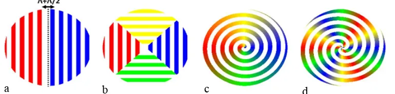
Figure 1. Illustration of the construction of a spiral grating. a) A shift of Λ/2 at the centre of a linear grating introduces a π phase shift between the two halves. b) Inserting orthogonal sections shifted by Λ/4 between the two halves creates a phase change around the centre in increments of π/2. c) Continuing to insert more segments ultimately leads to an Archimedean spiral structure with a continuous phase change of 2π around the centre. d) Example of how the concept can be extended to a 3-armed Archimedean spiral to increase the number of phase twists around the centre.
a b c d
from the proposed devices carries a topological charge also implies coherence of the source.
Figure 1 explains the concept schematically and shows how the phase shift between adjacent gratings can be used to introduce an azimuthal phase profile to the beam, thereby creating a vortex beam. First, a π phase shift is introduced between two halves of a linear grating by translating one of them by half the period, Fig. 1(a). Two new orthogonal sections of grating are then introduced between these two halves, Fig. 1(b), shifted from the first grating region by one- and three-quarters of a period, respectively. This process of adding more sections with intermediate spatial shifts, and therefore intermediary phase differences, is continued until its ultimate conclusion: an Archimedean spiral, Fig. 1 (c).
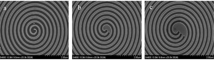
In addition to the desired phase change, which is determined by the phase relationship between the grating elements, the grating also determines the polarisation of the emitted beam. The period of the grating is designed to be 350 nm, in order to support the resonance wavelength in the active organic semiconductor, i.e. BBEHP-PPV (see Materials and Methods). As is well known, e.g. from one-dimensional grating resonators,16 the in-plane electric field is parallel to the grating groves. For the case of circular symmetry, this results in an azimuthally polarised beam.17 Given that the spiral grating is close to circular symmetry, we also expect the output beam from our device to be azimuthally polarised. Fig. 2 shows SEM images of the centre of the fabricated 1-, 2- and 3- arm spiral gratings.
a b c
Figure 2. SEM micrographs of the centre of the (a) 1-arm spiral, (b) 2-arm spiral and (c) 3-arm spiral gratings. The gratings have 350 nm period and are produced in silicon, which is then used as a master grating for the nanoimprint process of fabricating the actual laser.
Laser characterization
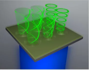
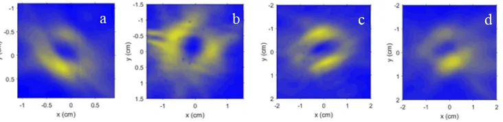
The fabricated organic vortex lasers, shown schematically in Fig. 3, were pumped with nanosecond laser pulses at a wavelength of 355 nm and the emitted beams imaged on a CCD camera (see Fig. S1). Typical beam cross-sections measured are shown respectively in Fig. 4a, b, c and d for lasers based on circular, 1-arm, 2-arm and 3-arm spiral gratings (l = 0, 1, 2, 3 respectively). As expected, the beams show annular shaped intensity profiles, with a vanishing intensity in the centre, denoting the position of the phase and polarisation singularity. Due to the azimuthal polarisation, all devices show a similar profile, including the one without topological charge. They
Figure 3. Schematic of active organic vortex lasers illustrating an array of devices, each one carrying a different topological charge of the emitted beam. The green lines correspond to constant phase regions – spiral in the case of an optical vortex with nonzero topological charge.
[image:7.612.124.488.56.341.2]exhibit a clear lasing threshold, (see Fig. S2, which shows a typical laser threshold of
4 kW/cm2) with the characteristic linewidth narrowing to a linewidth of < 0.6 nm
FWHM at threshold. We note that as the feedback for laser operation is provided by the second order grating, which is kept constant in terms of diameter, period and duty cycle, there is little variation in terms of threshold irrespective of topological charge. We also note deviations from the “ideal” annulus beam shape, which we attribute to a combination of asymmetries in the DFB grating and non-uniformities in the spin-coated polymer film.
Detection of the phase singularities
In order to differentiate between the different topological charges, it is necessary to assess the phase profile (topological charge) of the beams. This is especially crucial given the azimuthally polarised nature of the emitted beams, as even the l = 0 beam exhibits an annular intensity pattern due to its polarisation singularity.
Recent studies have developed a range of ways to determine the topological charge and its sign. As an example, this has been achieved using a Young's double slit geometry, used in the literature for both scalar18 and vector vortex beams.19,20 However, issues may arise with regard to alignment and clarity of the associated fringe pattern. Interestingly, the diffraction pattern of such a field by a triangular
Figure 4. Beam profiles recorded for the beams generated using (a) circular (l = 0), (b) 1-arm (l = 1), (c) 2-arm (l=2) and (d) 3-arm spiral gratings.
a b c d
[image:8.612.119.485.72.161.2]aperture provides a clearer fingerprint21-23 as it depends on the sign and the magnitude of the topological charge with distinguishing features in the centre of the pattern that help identify beams of differing charge. In addition, we have performed numerical studies highlighting that the diffraction pattern derived from the triangular lattice is more resilient to misalignment and beam asymmetry than the corresponding pattern of the double slit configuration. As such, we use both the two slits and triangular lattice approach for an accurate determination of the topological charge of the light field. For the double slit aperture, the topological charge leads to a displacement between the upper and lower part of the interference pattern by a number of fringes equal to the value of topological charge l. For the triangular aperture, the charge l is given by the number of dark lobes along each side of the diffraction pattern. In addition, for the vortex with l = 1 and 2 there is a bright spot in the centre of the diffraction pattern, while for vortex with l = 3 there is a dark spot in the centre, which can be explained by simple calculations (shown in SI) of the interference coming from three edges of the diffraction triangle.
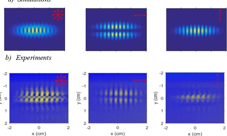
Figure 5. (a) Numerical simulations and (b) experimental measurements for the circular grating and the double-slit aperture. The left, middle and right columns show, respectively, the total field and the components of the polarisation perpendicular and parallel to the slits, as indicated by the arrows.
b) Experiments a) Simulations 3
As expected, for higher order vortices, i.e. l = 2 and l = 3, the triangular aperture yielded more conclusive results than the double slit experiment. To confirm the experimental findings, numerical simulations were carried out using Fresnel and Fraunhofer diffraction integrals (see SI for details).
The numerical simulations and corresponding double slit diffraction measurements for azimuthally polarised beams with topological charge l = 0 and l = 1 are shown in Fig. 5 and 6. The left, middle and right columns in each figure show, respectively, the total field, and the polarisation component perpendicular and parallel to the slits. We observe that there is a good agreement between simulations and the measurements; all of the characteristics of the interference pattern are supported by the measurements. For the polarisation perpendicular to the slits, the pattern is similar for both circular
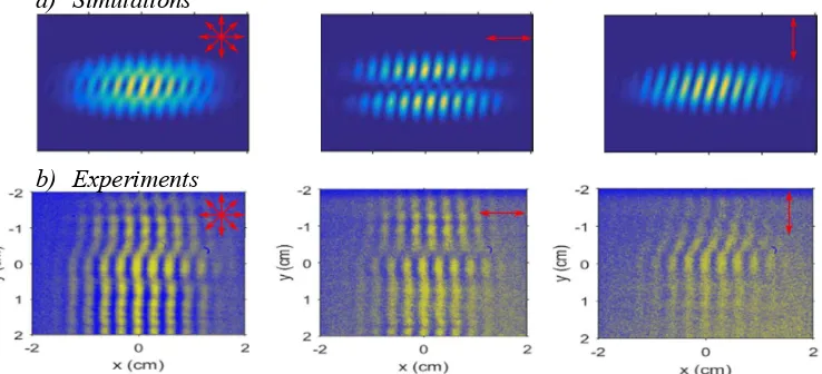
b) Experiments a) Simulations
Figure 6. (a) Numerical simulations and (b) experimental measurements for the 1-arm spiral grating and the double-slit aperture. The left, middle and right columns show, respectively, the total field and the components of the polarisation perpendicular and parallel to the slits, as indicated by the arrows.
[image:11.612.107.476.183.351.2]and spiral gratings, as predicted by numerical simulations: there is a zero-intensity region in the centre but no twist between the upper and lower parts of the fringes. The information concerning topological charge is then contained in the polarization component parallel to the slits. For the case of l = 0 there is no twist, while for l = 1 there is a twist, leading to a shift between the upper and the lower part of the fringes by one period of the fringes. The direction of the twist corresponds to the handedness of the vortex, which in turn is determined by the twist of the spiral grating.
[image:12.612.107.483.285.472.2]For higher values of l, we used diffraction from a triangular aperture, because the alignment was easier and the results clearer than for a double slit. For these apertures,
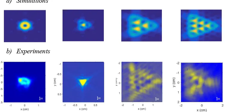
Figure 7. Numerical simulations (a) and experimental measurements (b) for circular grating (first column) and 1-arm, 2-arm and 3-arm spiral gratings corresponding, respectively, to the second, third and fourth column, for the triangular aperture experiment. Images are calculated using Fraunhofer diffraction and measured experimentally using a CCD camera at the Fraunhofer distance from the aperture, using the Fourier transforming 2f configuration of a lens.
a) Simulations
b) Experiments
l= l=
l= l=
is encoded in the number of dark lobes, equal to |l|+1, along each edge of an equilateral triangle shaped interference pattern, as seen in Fig. 7. Thus, we can conclude have successfully generated beams with l = 0, 1, 2 and 3.
CONCLUSIONS
We have shown that by the appropriate design of a feedback grating exploiting the phase-shift property of the Fourier Transform, organic semiconductor lasers can be made that, in a single step, generate vortex beams of desired topological charge. This was achieved by combining an Archimedean spiral grating of subwavelength thickness with a conjugated polymer gain medium. The topological charge of the vortex is controlled by the number of arms in the spiral, whilst the conjugated polymer provides high gain in the green region of the spectrum. An array of such lasers was made on a single substrate. The results demonstrate the simple fabrication associated with polymers, and these sources have the potential to be tuneable, flexible and (as polymer lasers develop) electrically pumped. Our results represent a significant advance in the field of structured light because the control of phase is achieved in a single optical element directly generating light with a desired phase profile, rather than by using a laser with separate external optical element. The simple and compact generation of beams with controlled topological charge demonstrated here could see applications in visible light communications, displays, metrology and quantum optics.
MATERIALS AND METHODS
Active gain material
We used BBEHP-PPV polymer as the active gain material,24 as it has a high gain coefficient and very low optical waveguide loss. The polymer has an absorption peak at 430 nm and emission maximum at 528 nm. It is spin-coated onto the gratings from a 15 mg/ml solution in chlorobenzene. The refractive index of BBEHP-PPV is slightly higher than that of the UV curable resist (UVcur06) that we use to form the grating. The effective index of the resulting thin film waveguide is approximately 1.5 and therefore the Bragg condition matches the PL peak wavelength when the period is 528 / 1.5 ≈ 350 nm. The duty cycle of the grating was chosen to be ~50%. The groove depth and the thickness of the active layer are, respectively, 80 nm and 200 nm.
Laser fabrication
The devices were fabricated using nanoimprint lithography.14,24 First, a silicon surface relief grating was fabricated using electron beam lithography and reactive ion etching. Example micrographs of the silicon gratings are shown in Fig. 2. These silicon gratings were used to cast daughter stamps in an elastomeric polymer, which in turn was used in a UV nanoimprint process to transfer the original pattern into a UV curable resist, forming the resonant grating. Finally, the organic semiconductor BBEHP-PPV (15 mg/ml solution in chlorobenzene) was spin coated onto these gratings inside a nitrogen glovebox to form the laser device.
Experimental setup
The polymer laser devices were optically pumped by a passively Q-switched pulsed solid-state laser emitting at 355 nm and focused to a spot size slightly smaller than the 500µm diameter of the grating. The emitted vortex beams, propagating perpendicular to the device surfaces, were imaged using a CCD camera. To measure spectral 3
characteristics and laser threshold, a neutral density wheel was used to control the pump pulse energy. Light emitted from the sample was then coupled into an optical fibre connected to a CCD spectrograph. To detect the phase profile, both double-slit and triangular apertures were used. The interference fringes were recorded using a CCD camera, mounted i) at the Fresnel distance away from the sample, in the case of the double-slit experiment and ii) in the Fraunhofer regime, using a Fourier transforming 2f configuration of a lens, for the triangular aperture experiment. In the case of the double-slit aperture, the interference fringes were recorded after passing through a polariser decomposing the field into two orthogonal polarisations: parallel and perpendicular to the slits.
ASSOCIATED CONTENT
Supporting Information
Section A: Experimental details
Section B: Mathematical details
AUTHOR INFORMATION
Corresponding Author
* [email protected]; [email protected]
Author Contributions
The manuscript was written through contributions of all authors. All authors have given approval to the final version of the manuscript.
†
These authors contributed equally.
ACKNOWLEDGMENTS
The authors gratefully acknowledge funding from the EPSRC Programme Grant EP/J01771X/1/ “Challenging the limits of Photonics”. JMEG acknowledges funding from the EPSRC DTG EP/L505079/1. IDWS and TFK also acknowledge Royal Society Wolfson Research Merit Awards. Author contributions: TFK, IDWS and KD conceived the investigation. DS proposed and designed the spiral gratings. YW made the master spiral gratings by electron beam lithography. MEP, JMEG and AKB made and measured the polymer lasers guided by GAT and IDWS. MEP was responsible for developing and implementing the measurements of topological charge guided by KD and IDWS. The manuscript was written by DS, YW, TFK and IDWS and edited by all authors. Competing interests: The authors declare that they have no competing interests. Data and material availability: All data needed to evaluate the conclusions in the paper are present in the paper and/or Supporting Information. Data supporting this research can be found at [INSERT DOI].
REFERENCES
1. Cai, X.; Wang, J.; Strain, M. J.; Johnson-Morris, B.; Zhu, J.; Sorel, M.; O'Brien, J. L.; Thompson, M. G.; Yu, S. Integrated Compact Optical Vortex Beam Emitters. Science 2012, 338, 6105, 363-366.
2. Huang, L.; Chen, X.; Mühlenbernd, H.; Zhang, H.; Chen, S.; Bai, B.; Tan, Q.; Jin, G.; Cheah, K.-W.; Qiu, C.-W.; Li, J.; Zentgraf, T.; Zhang, S. Three-3
Dimensional Optical Holography Using a Plasmonic Metasurface. Nat. Comm.
2013, 4, 2808.
3. Smithwick, Q.Y.; Disney Enterprises, Inc. Optical Vortex 3D Displays. US 20150201186 A1, 2015.
4. Singh, R.; Narayanan Unni, K. N.; Solanki, A.; Deepak. Improving the Contrast Ratio of OLED Displays: An Analysis of Various Techniques. Optical Materials 2012, 34, 4, 716-723.
5. Nguyen, L. A.; He, H.; Pham-Huy, C. Chiral Drugs: An Overview. Int J Biomed Sci. 2006, 2, 85–100.
6. Feringa, B. L. Nobel Lecture: The Art of Building Small, From Molecular Switches to Motors. Nobelprize.org. Nobel Media AB 2014. Web. 9 Sep 2017
7. Tkachenko, G.; Brasselet, E. Optofluidic Sorting of Material Chirality by Chiral Light. Nat. Comm. 2014, 5, 3577.
8. Yu, P.; Li, J.; Tang, C.; Cheng, H.; Liu, Z.; Li, Z.; Liu, Z.; Gu, C.; Li, J.; Chen, S.; Tian, J. Controllable Optical Activity with Non-Chiral Plasmonic Metasurfaces. Light: Science & Applications 2016, 5, e16096; doi:10.1038/lsa.2016.96
9. Khorasaninejad, M.; Chen, W. T.; Devlin, R. C.; Oh, J.; Zhu, A. Y.; Capasso, F. Metalenses At Visible Wavelengths: Diffraction-Limited Focusing and Subwavelength Resolution Imaging. Science 2016, 3, 1190-1194.
10.Miao, P.; Zhang, Z.; Sun, J.; Walasik, W.; Longhi, S.; Litchinitser, N. M.; Feng, L. Orbital Angular Momentum Microlaser. Science 2016, 29, 464-467.
11.Forbes, A. Controlling Light’s Helicity At the Source: Orbital Angular Momentum States from Lasers. Phil. Trans. R. Soc. A. 2017, 375, 20150436.
12.Wang, X-Y.; Chen, H-Z.; Li, Y.; Li, B.; Ma, R-M. Microscale Vortex Laser with Controlled Topological Charge. Chin. Phys. B 2016, 25, 12, 124211.
13.Martins, E. R.; Li, J., Liu. Y., Zhou, J.; Krauss, T. F. Engineering Gratings for Light Trapping in Photovoltaics: The Supercell Concept. Physical Review B
2012, 86, 041404(R).
14.Martins, E. R.; Wang, Y.; Kanibolotsky, A. L.; Skabara, P. J.; Turnbull, G. A.; Samuel, I. D. W. Low-Threshold Nanoimprinted Lasers Using Substructured Gratings for Control of Distributed Feedback. Advanced Optical Materials
2013, 1, 8, 563-566.
15.Samuel, I. D. W.; Turnbull, G. A. Organic Semiconductor Lasers. Chem. Rev.
2007, 107, 4, 1272–1295.
16.Turnbull, G. A.; Andrew, P.; Jory, M. J.; Barnes, W. L.; Samuel, I. D. W. Relationship Between Photonic Band Structure and Emission Characteristics of a Polymer Distributed Feedback Laser. Phys. Rev. B 2001, 64, 125122
17.Turnbull, G. A.; Carleton, A.; Tahraouhi, A.; Krauss, T. F.; Samuel, I. D. W.; Barlow, G. F.; Shore, K. A. Effect of Gain Localization in Circular-Grating Distributed Feedback Lasers. Appl. Phys. Lett. 2005, 87, 201101.
18.Sztul, H. I.; Alfano, R. R. Double-Slit Interference with Laguerre-Gaussian Beams. Opt. Lett. 2006, 31, 7, 999-1001.
19.Li, Y.; Wang, X.-L.; Zhao, H.; Kong, L.-J.; Lou, K.; Gu, B.; Tu, C.; Wang, H.-T. Young's Two-Slit Interference of Vector Light Fields. Opt. Lett. 2012, 37, 11, 1790-1792.
20.Qi, J.; Wang, W.; Li, X.; Wang, X.; Sun, W.; Liao, J.; Nie, Y. Double-Slit Interference of Radially Polarized Vortex Beams. Opt. Eng. 2014, 53, 4, 044107.
21.Hickmann, J. M.; Fonseca, E. J. S.; Soares, W. C; Chavez-Cerda, S. Unveiling a Truncated Lattice Associated with a Triangular Aperture Using Light's Orbital Angular Momentum. Phys. Rev. Lett. 2010, 105, 053904.
22.Mourka, A.; Baumgarti, J.; Shanor, C.; Dholakia, K; Wright, E. M. Visualization of the Birth of an Optical Vortex Using Diffraction from a Triangular Aperture. Opt. Exp. 2011, 19, 7, 5760-5771.
23.Stahl, C.; Gbur, C. Analytic Calculation of Vortex Diffraction by a Triangular Aperture. JOSA A 2016, 33, 6, 1175-1180.
24.Wang, Y.; Tsiminis, G.; Kanibolotsky, A. L.; Samuel, I. W. D.; Turnbull, G. A. Nanoimprinted Polymer Lasers with Threshold Below 100 W/cm2 Using Mixed-Order Distributed Feedback Resonators. Opt. Exp. 2013, 21, 12, 14362-14367.
For Table of Contents Use Only 3