1 2 3 4 5 6 7 8 9 10 11 12 13 14 15 16 17 18 19 20 21 22 23 24 25 26 27 28 29 30 31 32 33 34 35 36 37 38 39 40 41 42 43 44 45 46 47 48 49 50 51 52 53 54 55 56 57 58 59 60 61 62 63 64 65 66 67 68 69 70 71 72 73 74 75 76 77 78 79 80 81 82 83 84 85 86 87 88 89 90 91 92 93 94 95 96 97 98 99 100 101 102 103 104 105 106
Resolving Target Ambiguity in 3D Gaze Interaction
through VOR Depth Estimation
Diako Mardanbegi Lancaster University Lancaster, United Kingdom [email protected]
Tobias Langlotz University of Otago Dunedin, New Zealand [email protected]
Hans Gellersen Lancaster University Lancaster, United Kingdom
B
A
A
B
A
B
[image:1.612.108.507.160.313.2](a) (b) (c)
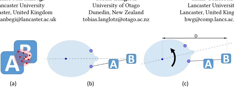
Figure 1:VOR Depth Estimationis a novel technique enabling disambiguation of gaze targets in 3D environments. Ambiguity arises due to gaze imprecision when objects overlap in the field of view (a), as a result of their placement in 3D (b). This can be resolved when users complete the selection with a head rotation while maintaining gaze focus based on the vestibulo-ocular reflex (VOR), allowing target depth to be obtained from comparison of the angular velocities of eye and head.
ABSTRACT
Target disambiguation is a common problem in gaze inter-faces, as eye tracking has accuracy and precision limitations. In 3D environments this is compounded by objects overlap-ping in the field of view, as a result of their positioning at dif-ferent depth with partial occlusion. We introduceVOR depth estimation, a method based on the vestibulo-ocular reflex of the eyes in compensation of head movement, and explore its application to resolve target ambiguity. The method esti-mates gaze depth by comparing the rotations of the eye and the head when the users look at a target and deliberately rotate their head. We show that VOR eye movement presents an alternative to vergence for gaze depth estimation, that is feasible also with monocular tracking. In an evaluation of its use for target disambiguation, our method outperforms vergence for targets presented at greater depth.
Permission to make digital or hard copies of all or part of this work for personal or classroom use is granted without fee provided that copies are not made or distributed for profit or commercial advantage and that copies bear this notice and the full citation on the first page. Copyrights for components of this work owned by others than ACM must be honored. Abstracting with credit is permitted. To copy otherwise, or republish, to post on servers or to redistribute to lists, requires prior specific permission and/or a fee. Request permissions from [email protected].
Conference’17, July 2017, Washington, DC, USA
© 2019 Association for Computing Machinery. ACM ISBN 978-x-xxxx-xxxx-x/YY/MM. . . $15.00 https://doi.org/10.1145/nnnnnnn.nnnnnnn
CCS CONCEPTS
•Human-centered computing→Human computer in-teraction (HCI);Gestural input; •Computing method-ologies→Virtual reality;
KEYWORDS
Vestibulo-ocular reflex, depth estimation, eye tracking, ver-gence, disambiguation
1 INTRODUCTION
Eye tracking is compelling for interaction as it is natural for users to direct their gaze to point at targets of interest. However, gaze pointing has inherent limitations in accuracy and precision, as eye movement is jittery and gaze estimation subject to noise and imperfect calibration [20, 36]. In 2D interfaces, this can be managed by spacing of objects and targeting assistance. In contrast, in 3D interfaces, objects can be placed at different depth and depending on viewpoint appear as overlapping in the field of view, resulting in target ambiguity. Figure 1.a&b illustrate the problem. While a user is looking at object B, they might inadvertently select object A as it is close to the line-of-sight and partially occludes B. Ambiguity as to which of the two objects the user is looking at can be resolved with estimation of gaze depth, for comparison against the depth at which the objects are rendered.
In this paper, we introduceVOR depth estimationas a novel method for 3D gaze estimation that can be used to resolve
target ambiguity in 3D interfaces (stereoscopic displays, or VR/AR environments). In our technique, users select an ob-ject by focusing their gaze on the target while deliberately shaking their head, as illustrated in Figure 1.c. The head movement is compensated by eye movement in the oppos-ing direction, based on the rotational vestibulo-ocular reflex (VOR) that stabilizes the retinal image during movement of the head. The technique takes advantage of the additional sensors available in head-mounted displays (e.g., VR/AR de-vices), for precise tracking of head motion. It does not track gaze depth continuously but relies on head movement to trig-ger depth estimation. As it is based on relative eye movement, it is not reliant on accurate calibration.
Our contribution starts with developing the theoretical foundation of VOR depth estimation. We then report a feasi-bility study in which we empirically evaluate depth estima-tion performance of our technique on data collected from 4 participants, indicating advantages over vergence for es-timation at greater depth. This is followed by evaluation of the technique in application to the target disambiguation problem in a user study. Users were presented with pairs of targets rendered at different depth and depth estimation was done in real-time using our technique. Selection accuracy was comparable with vergence for targets presented within 2m of the user, but superior for targets presented at larger distances.
In sum, the contributions of this work are:
• A novel technique for gaze depth estimation based on VOR eye movements.
• Evaluation of depth estimation performance in com-parison with a vergence-based method.
• Demonstration and evaluation of the technique for target disambiguation in virtual reality.
2 RELATED WORK
There has been a body of research addressing the accuracy and precision issues of gaze-based interaction. In particular, the resulting problems when several possible gaze targets are in close proximity, have been addressed for conventional 2D user interfaces [6, 13, 16, 39].
Similarly, gaze-based interaction has been utilized in 3D user interfaces. Here, in addition to target proximity, oc-clusions resulting from target objects (partially) occluding each other have been identified as challenges and are dis-cussed when pointing is done by gaze [8] or another modality [12, 24, 37]. The majority of these works require changes in the UI (e.g., enlarging and magnifying the UI) or a re-arrangement of the coarsely selected target candidates for final selection.
Some other solutions opted for combining head and hand for improving general interaction or to use head and hand to
improve otherwise imprecise target selection with gaze [4, 5, 26, 38]. These non-depth based alternatives rely on visual feedback to the user upon which they can act to refine their input in an additional step. A specific example is Pinpointing (Kyto et al. 2018), where the user first looks and signals intent to select (press button, or dwell), then in second step corrects input by head and confirms (release button). In contrast, our approach permits selection in one step: user looks and shakes head to signal intent to select, and the disambiguation is achieved implicitly based on the head-shake, without any further interaction step.
In this work, we explore a different strategy for overcom-ing precision and occlusion issues in gaze interaction for 3D environments which infers the gaze depth from the eye and head tracking data. When looking into existing 3D gaze estimation methods that utilized the computed depth of the gaze, we identify three primary methods:
Gaze ray-casting methods.Techniques in this category are based on ray-casting a single gaze ray with the 3D scene where the intersection of the first object and the gaze ray is taken as the 3D point of regard [27, 40]. The gaze ray could either be the visual axis of the left eye or the right eye or an average gaze ray shot from an imaginary cyclopean eye situated midway between the two eyes1. These techniques are only possible if the gaze ray directly intersects an object and they also do not address the occlusion ambiguity when several objects are intersecting the gaze ray.
Intersection of multiple gaze rays.These techniques apply gaze estimation in 3D by intersecting multiple gaze rays either the rays from the left and the right eyes [10, 18] or the gaze ray of a single eye sampled at two different viewing angles [30]. These techniques do not rely on intersection with 3D geometries and estimate the gaze point in 3D only based on information from the observer.
Vergence.These techniques obtain the 3D gaze point via triangulation using either horizontal disparity between the left and the right 2D gaze points [1, 7, 9, 11, 33] or the inter-pupillary distance [2, 15, 22, 25]. Others have also used machine learning techniques to estimate gaze depth from vergence [32, 42]. Weier et al. [43] introduced a combined method for depth estimation where vergence measures are combined with other depth measures (such as depth obtained from ray casting) into feature sets to train a regression model to deliver improved depth estimates.
These primary methods for computing gaze depth informa-tion for interacinforma-tion in 3D are all based on the rays described by the users gaze, optionally combined with the scene geom-etry. However, some research also looked into other means to compute the gaze depth. For example, Alt et al. [1] uses
1The average ray is referred to as "Combined Gaze" in Tobii Pro SDK of the
VR Integration [19]
pupil diameter to infer the depth of the gazed target when in-teraction with stereoscopic content. This technique is based on the assumption that the pupil diameter changes as a func-tion of target distance given that lighting condifunc-tions remain constant [35]. Mercier et al. [29] used autorefractors to infer the gaze depth by measuring the eye’s accommodative state. Common to these techniques is that the required information can also be inferred from the information obtained from a single eye only.
In this paper, we propose an alternative method for gaze depth estimation which is based on the coupling between head and eye movements, more specifically utilizing the vestibulo-ocular reflex (VOR). The relationship between head, eye (their VOR gain) and specific target depths have been studied before (e.g. [3, 41]), however, to our knowledge, it has never been used for depth estimation. In our technique, we use eye tracking data in combination with the information obtained from additional sensors for target selection. Others have also utilized the additional tracking sensors available on commercial head-mounted displays for enhancing 3D gaze estimation [21, 23, 26].
3 VOR DEPTH ESTIMATION
Eye-head coordination is a complex topic that is extensively studied not only in Cognitive Science but also for Human-Computer Interaction. In this work, we are particularly inter-ested in exploring the eye-head coordination to resolve ambi-guity in gaze interaction. The proposed technique addresses the ambiguity due to occlusion by inferring the depth of the gazed target after a deliberate head movement performed by the user (as illustrated in Figure 1b&c). The underlying assumption of this method is that the users keep their gaze fixed on the target during head movements, however, the eyes move because of thevestibulo-ocular reflex(VOR).
During VOR eye movements, the head and the eyeball could be considered as two coupled counter-rotating objects in 3D where both rotate together but in opposite directions. The gain of the VOR eye movement is defined as angular eye velocity divided by angular head velocity (hereafter referred to as VG which stands for VOR gain),
VG= dθE
dθH
. (1)
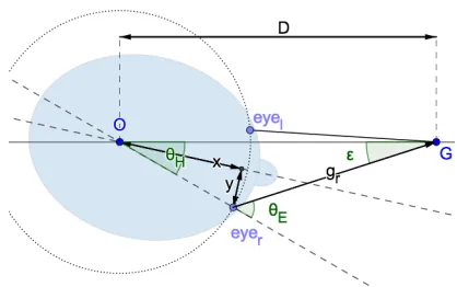
[image:3.612.332.541.97.228.2]WhereθE andθH are rotations of the eye and the head re-spectively. The VG is ideally 1, however, since the center of the eyeball does not coincide with the center of rotation of the head (O), the eye and the head do not rotate the same amount. The offsets between the center of rotation of the eye and the head are shown asxandyin Figure 2. Because of the offset, and the fact that the eyes are carried by the head during head movements,θE andθH vary by a small amountεwhereθE =θH +ε. Theεrepresents the amount
Figure 2: Basic geometry (top-view) of two eyes fixating on a point G, when the head is rotated to the right byθH degrees
while the gaze is fixed on the pointG. The large dashed circle shows the locus of eyeball centers during head rotations.
that the gaze directionдr rotates in space during VOR even though the fixation point is fixed. Keeping theθHangle fixed,
εchanges as a function of depth (D), whereεincreases as the fixation pointGgets closer thus increasing the gain value. Based on this we can conclude that the angular velocity of the eye during VOR is higher than the angular velocity of the head at closer distances simply because the eye has to rotate a larger angle.
From the geometry shown in Figure 2, one can also see thatεis also dependent on the head angleθH (as mentioned in previous works [41]). Because of this, it’s desired that the VOR gain is always obtained at a specificθH meaning that the specificθH value used in the calculation has to be cov-ered by the head movement. We take this into account when evaluating the depth estimation performance, however, as we describe later, when evaluating the disambiguation per-formance, we did not constrain the head movements and the VG samples were taken at an angle where the head velocity was maximum.
4 DEPTH ESTIMATION PERFORMANCE
In a first step we were interested in the general feasibility of utilizing the VOR gain to compute depth information that can later be used to reduce ambiguity in gaze based selection. We also explore if and how depth information can be obtained from the VOR gain of a single eye. To test the feasibility of our concept, we implemented it in a controlled virtual 3D environment where we could easily position the fixation targets at different distances and different angles. More importantly, we could accurately measure the head and the eye rotations. In our experiment, we wanted to study the relationship between VOR gain and target depth and for that we recorded the eye and the head movements of a few subjects when they were looking at targets at different
depths and shaking their head. We also measured the distance between the pupil positions of the left and the right eyes to compare how VOR gain and inter-pupillary distance change across different depths.
Setup & Apparatus
An HTC Vive virtual reality setup with integrated eye tracker from Tobii [19] was used to collect eye and head movement data. The program used for the experiment was developed in Unity engine. Both eye and head data were synchronized by the Tobii SDK and they were both collected at 120Hz.
Participants
We recruited 4 participants (3 male and 1 female, with the average age 32 (SD=3.8)) to take part in the experiment.
Procedure
The participants were sat on a chair in a comfortable posture while the head was facing straight ahead. They were asked to put on the VR headset and adjust the straps for comfort. Before each recording, the participants conducted a gaze calibration with 5 points using the default Tobii calibration procedure. The main task was to fixate on a target and to move the head 10 times left to right and vice-versa continu-ously in the transverse plane. The fixation target was placed at different distances from 20 cm to up to 1000 cm (measured from the center of the headset). The target was a white color circle with a cross at its center. To help the participants to keep their head aligned with the target before starting head movements, a cross indicated by two thin lines was shown in front of their view at the same depth as the target and they were instructed to keep the center of the cross aligned with the center of the target at the beginning of each trail. Partic-ipants were also asked to keep their gaze fixed at the center of the target at all time. At the beginning of the recording the target was placed at 70 cm depth and then it moved closer and stopped at the first distance (20 cm). This converge-assist stepwith 6 sec duration was meant to help the users to converge their eyes at such a close distance which would otherwise be very difficult for some people. The target then became green indicating that the head movement can be started. To ensure that the head movements are done in the transverse plane, the participants were instructed to try to keep the horizontal line of the cross aligned with the target during the movement. The head rotation was limited to±20◦
of each side and the target became red as soon as the head angle exceeds this angle indicating to the participant that they should stop the movement and reverse the direction. A tick-tack sound was playing in the background guiding the participants to adjust the speed of the movement by align-ing the tick-tack sounds with extreme right and left angles.
The desired speed for the head shake was set to 50◦/sec
(0.4◦/f rame). This value was decided empirically during a
pilot experiment when we tested 4 different speeds (30,40,50, and 60)[◦/sec]where 50◦/secyielded smoother side-to-side
head movements and it was not too fast for the users. We asked the users to do 10 head movements. After count-ing 10 movements, the target became white indicatcount-ing that the user can stop the movement. The target then moved to the next distance (4 second transition). After the last distance, there was afar-to-close stepwhere the target moved closer all the way to 20 cm and the participant was asked to fixate on the target while aligning their head with the target. We used this step to measure the interpupillary distance as an indication of vergence angle at different distances. Except for the first and the last steps of the recording, the target size was kept constant at 2◦of visual angle at all distances. Implementation & Data Processing
To be able to calculate the VG in our study we recorded the following main values: target distance, pupil positions, head orientation (roll-yaw-pitch angles) and both gaze rays.
We applied a 3rd order Butterworth filter with the Cutoff-frequency of 0.04 on all raw inputs from head and eye to smooth the signals. Figure 3.a and 3.b show the raw and the filtered eye and head rotation signals for 3 horizontal head movements of 40◦from left to right or vice-versa whilst the user was looking at a target located straight in front of the head. A Savitzky-Golay [14] filter using a 3rd order polynomial and a window size of 100 was then used to differ-entiate the rotation signals and produce velocity. No further filtering was done on the velocity signals. Figure 3.c shows example velocity signals corresponding to the head and eye signals shown in the figure. The blue segments shown on the signals indicate the time where the target was within
±5◦angular distance from the head straight vector. The VG value was then calculated by dividing the eye velocity by the head velocity.
We used the raw pupil position data recorded during the far-to-close step of the recording to measure a relative in-terpupillary distance. The pupil position data obtained from the Tobii SDK are normalized pupil position in the sensor area where (0, 0) is the top left and (1, 1) is the bottom right of sensor area. We subtracted the horizontal values of pupil positions of the right eye and the left eye to get a signal that can show how the interpupillary distance has changed for different fixation distances. We refer to this signal as theIPD signalfor the rest of the paper even though it’s not an actual measurement of the IPD. Because the data was captured in high frame rate, there were occasions were we had multiple values per depth which we then took the median value. To remove spikes and noise from this signal, we first removed the outlier samples by calculating the rolling median signal
−20 0 20 40
de
g
(a)
θE
raw signal filtered signal
−20 −10 0 10 20
de
g
(b)
θH
raw signal filtered signal
1500 1550 1600 1650 1700 1750
frame 0
50 100 150 200
de
g/se
c
(c)
θE_vel
[image:5.612.57.292.93.280.2]θH_vel
Figure 3: The raw and the filtered signals of eye (a) and head (b) rotations of 3 head movements for a random subject with the target 0.3 m away from the head. Figure (c) shows the corresponding velocity signals. The blue segments indicate the region where the angle between the target, pointO, and the head vector was within±5◦.
with a window size of 50 and then removing any sample that its distance from the median was larger than a threshold. The values for the window size and the threshold were found through trial and error and they worked best on our data.
Results
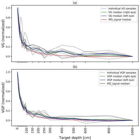
We calculated the gain by dividing the eye velocity by the head velocity. This value gets very unstable for the velocity signals close to zero. We collected the VG for a particular head angleθH =0 where the velocity signals have their high-est values. We also included a window size of±5◦ around this point and took their median VG value at each head movement. There were 10 movement strokes for each dis-tance and thus 10 VG values per disdis-tance. Values outside the interquartile range were considered as outliers and were removed. The median of the remaining VG values was taken as the final VG value at every distance. In order to be able to compare the VG values between subjects, we normalized the VG curve for each subject by mapping the VG values into the range [0,1] where 0 corresponds to the VG value at D=1000 cm and 1 corresponds to the VG value at D=20 cm as measured for each individual subject. Figure 4.a shows the VG ratio obtained at each depth from the right eye of all participants.
We found the pupil data obtained from the tracker less noisier than the gaze data. This prompted us to check the feasibility of using pupil data instead of gaze data which could also make the proposed method independent from
0.0 0.2 0.4 0.6 0.8 1.0
VG (normalized)
(a)
Individual VG samples VG median (right eye) VG median (left eye) IPD_signal median
0
100 150 200 250 300 400 500 600 800 1000
Target depth [cm] 0.0
0.2 0.4 0.6 0.8 1.0
VGP (normalized)
(b)
Individual VGP samples VGP median (right eye) VGP median (left eye) IPD_signal median
Figure 4: Normalized VG (a) and VGP (b) curves obtained from all participants. All individual samples (collected from both eyes) are shown in gray color. The green and the blue curves show the median of samples (across all participants) for right eye and left eye respectively. The IPD signal ob-tained during the far-to-close step is also shown in red.
gaze calibration. Thus, we definedVGP (VOR gain using pupil position) as the velocity of the pupil position (in the eye image) divided by angular head velocity:
VGP=dPC
dθH
(2) where PC is the center of pupil in the eye image.
The results showed that theVGPvalues obtained from the pupil center data give us smoother curves (see Figure 4).
We collected the IPD signals obtained during the far-to-close step for all participants. Figure 4 shows the median of the normalized IPD signals from all participants as well as the median VG and VGP curves. The IPD signals were normalized the same way as the VG, where 0 corresponds to D=1000 cm and 1 corresponds to D=20 cm. By comparing the IPD curves with the VG and VGP curves, we can see that the relationship between the VOR gain and depth is very similar to the relationship between the vergence and distance. The resolution (defined as the amount of change in the measured value per unit distance) of our method seems to be slightly higher than the IPD signal at distances greater than 1 m. This can indicate that the VOR based method may perform better at larger distances when used for depth estimation, however,
[image:5.612.320.555.95.329.2]this difference could also be due to noise in calculating the VOR gain.
Depth Estimation
We found the rational function shown in Eq.3 to best describe the vergence and VG curves.
S(D)= D
2P 0+DP1
D2P
2+DP3+P4
(3) Where D is the fixation depth. We used the inverse ofS(D)
(Eq.4) to estimate the target depth from the VG or the ver-gence values in the following.
D(S)=
−S P3+P1+
q
−4S2P2P4+S2P2
3+4S P0P4−2S P1P3+P12 2(S P2−P0)
(4)
WhereScould be either vergence or VG values measured at depth D.
5 EVALUATION OF TARGET DISAMBIGUATION
We further conducted a user study to see the feasibility of using our technique for disambiguation in a VR selection task. We combined our technique with head gestures as a method for object selection. Our assumption, however, was that the user’s gaze remains fixed on the target when the selection is confirmed by deliberate head shakes. We refer to this task as gaze & head-shake selection task or in short asgaze & head-shake.
We were further interested in exploring whether the pro-posed method can implicitly disambiguate the target using only the natural head shifts that follow gaze shifts when aiming at a new target. Thus, besides the gaze&head-shake selection task, we asked the participants to do another task where they selected the target just by looking at it without the need for doing any explicit head shakes. We later checked the performance of our method in this task where the VOR gain was obtained only during natural head shifts. Another aim for this task was to mimicideal gazeselection where the main target was always selected 2 seconds after they shift their gaze towards the target even when the gaze was hitting the other target. We later consider the users’ perceived task load of the ideal gaze selection as a baseline for comparison.
Study Design
In our study addressing target ambiguity in 3D environments the participants had to select one of two displayed targets (target ’A’ and target ’B’), each located at a different depth with the distant target partially occluded by the closer tar-get. One of the targets was considered as the main target which had to be selected. Given the range of possible target distances, we applied the following criteria to selecting th
Short-range
Wide-range
1.5
0.5 7
0.3
Distance [m] 0.5 0.8
Angular offset
0.
2
1.
0
0.
4
0.
65 2.0
3.
0
10.
0
0.
[image:6.612.316.554.98.221.2]2
Figure 5: The top figure shows the two different arrange-ments for target depth used in the user study: short-range and wide range. The gray regions around each depth indi-cate the acceptable range for estimated depth for each target depth. For example, in the short-range condition, the target at 0.8 m will get selected if the estimated depth is between 0.65 m and 2 m. The targets were also tested at different an-gular offsets from the central direction (as shown in the bot-tom figure).
distance. We considered two common conditions that could happen when interacting with 3D environments: A short-range condition of 20 cm to 1 meter which is within reach. Most of the manual manipulations take place in this space. Secondly, a wide-range condition where the occluded target is usually a background object farther away from the user. In each condition, we considered 3 different depths ([0.3 m, 0.5 m, 0.8 m] for the short-range condition and [0.5 m, 1.5 m, 7 m] for the wide-range condition as shown in Figure 5). In each condition, we considered all 2 permutations of the 3 distances leading to 12 combinations of distances 6 from each condition.
We also considered different angular offsets. The two tar-gets were positioned along a ray starting from the center of the head and we considered 9 angular offsets (0◦,±10◦,
±25◦,±35◦,±45◦) for this ray to test different positions at
the user’s field of view. We excluded the 0◦angle as it does
not require any head shift. Overall, we had 12 (depth pairs)
×9 (angles)=108 trials in the gaze & head-shake task and 12 (depth pairs)×8 (angles)=96 trials in the ideal gaze task. The depth and angle conditions were ordered randomly. To avoid distant targets to appear as very small, we kept the size of the targets constant (1.5◦of visual angle) regardless of their distance.
For this study, we compared our method against a vergence-based method. However, we tested three different modes of our depth estimation method: depth obtained from the VOR gain of the left eye (VGPL), the right eye (VGPR), and the final mode using the average distance obtained from both
eyes (VGPAV). Our user study was conducted as a within-subject study with 4 methods comprised of the 3 modes of our implementation and a vergence-based method. Overall, we have 4 (methods)×2 (depth conditions)×5 (angular offset conditions) full factorial design for the gaze & head-shake task and 4 (methods)×2 (depth conditions)×4 (angular offset conditions) in the ideal gaze task.
The gray region around each depth in Figure 5 indicates the acceptable deviation that the estimated depth could have from the target depth. From the result of the experiment (Figure 5), we already expected to have larger errors for more distant targets. Therefore, the acceptable range of distances was set to be smaller for closer targets than for distant targets. The acceptable regions around targets were also set to be smaller for the short-range scene as the selection required higher accuracy for depth estimation. In the wide-range scene, we accepted larger depth estimation errors as the targets were farther apart. The acceptable value for depth was set to 10 m because the farthest sample during our depth calibration was taken at 10 m and no extrapolation was done for depth estimation (depth estimation method is described further in the following).
Participants
We recruited 13 participants (11 male and 2 female, mean age=29.38 (SD=5.9)) to take part in the user study. 6 of the participants were right eye dominant, 5 were left eye domi-nant and 2 did not answer the question because they were unsure. Besides 2 participants, all the others had tried virtual reality before. 6 participants used glasses or contact lenses in the study. The software crashed in the middle of recording for one of the subjects and he did not want to continue. Also, the depth calibration failed for one of the participants (thus no model was detected for depth estimation) and we couldn’t run the selection task for that subject. We excluded the data from these 2 participants.
Procedure
Our user study was divided into two parts. First, the ideal gaze task followed by the gaze & head-shake task. The order of the tasks was not counterbalanced as performing the gaze & head-shake task first may have influenced the participants’ perception on what type of head movement was required and we had no intention to compare the tasks. After providing consent and demographic information, we used the same procedure from the previous study to collect 18 samples at different depths for building the model used for depth estimation. We refer to this step as depth calibration in the rest of the paper. Right after the depth calibration step the participants had the chance to do 10 test trials to practice the condition.
Ideal gaze selection.In each trial, two targets were shown to the user and it was indicated which of the targets has to be selected. Selecting the main target is simply by shifting the gaze towards the target. We provided feedback for con-firmation that was not based on our disambiguation method, but always selected the main target correctly after 2 seconds from the moment where the distance between the gaze and the target goes below the threshold of 3◦. We checked the true performance after offline analysis. After each selection, the user was guided back to the neutral position.
Gaze & head-shake selectionSimilarly to the first part, in each trial, two targets were shown to the user and it was in-dicated which of the targets has to be selected. Selecting the main target is by looking at it and shaking the head until the depth estimation is done and selection is confirmed. The num-ber of head shakes was not fixed and selection was always done after 50 samples are collected at head velocities higher than 50◦/sec. This value was decided empirically based on
the data collected during the pilot experiment, which was equivalent to 40◦head movement from side to side. It is pos-sible to perform the selection with only one head movement but typically more than two head movements were required to confirm the selection.
Similar to the ideal gaze task, the participants had to move their head back to the neutral position before the next trial. The participants completed a questionnaire at the end of each session, which contained questions and comments on their general preference.
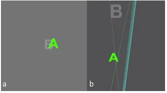
Figure 6: (a) A screenshot of the user’s view, and (b) top view showing the two targets, left and right gaze rays focusing on the closer target and head direction (cyan line).
Data Processing
Based on our findings from our initial experiment, we used pupil data for calculating the VG values (VGP) in our user study. we used the function described in Eq. 3 to fit ourVGP samples collected from the depth calibration step. The model was built for each individual immediately after the depth calibration step. We then used Eq.4 to estimate the target depth from the medianVGPvalue measured in each trial.
In each trial, theVGPwas calculated in realtime separately for each eye whenever the head velocity was higher than
[image:7.612.353.524.436.532.2]short-range wide-range Depth condition
0 20 40 60 80 100
C
or
re
ct
se
le
ct
io
n
[%
]
VGPAV
VGPL
VGPR
Vergence
(a)
0 10 25 35 45
Angular offset [deg] 0
20 40 60 80 100
C
or
re
ct
se
le
ct
io
n
[%
]
VGPAV
VGPL
VGPR
Vergence
[image:8.612.56.304.93.336.2](b)
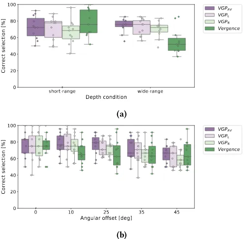
Figure 7: Percentage of successful selection in the gaze & head-shake selection task.
50◦/s(0.4◦/f rame). The fixation depth was then calculated
separately fromVGP of each of the eyes. The average of the two estimated depths was taken as the final depth. We selected the target if the estimated depth was within the ac-ceptance range of target (see Figure 5). We provided feedback to the user by drawing the selected target in green. Realtime depth estimation was also done using IPD signal as well as
VGPof each single eye and they were all logged into one file for further comparisons.
Results
For each participant, we counted the number of trials where the main target was selected correctly based on the depth esti-mation using any of the four methods (VGPAV,VGPL,VGPR,
andV erдence). We performed a three-way repeated
mea-sures ANOVA to compare the success rate of different meth-ods for two different depth conditions (short-range scene & wide-range scene) at different angular offsets.
The average selection time with our technique was 0.56 sec (SD 0.37) which was measured from the beginning of each trial to the moment where the selection was done. This was the average time needed to take 50 samples at high head velocities as described before.
Figure 7a shows the results comparing the proposed VOR-based method and the vergence method in short-range and wide-range scenes. The mean of the successful rate was above 60% for the proposed method even when using a single eye
only. We found no significant main effect for method or depth conditions. We observed significant two-way interactions for method×depth condition (F(3,30)= 17.22,p =.000). Therefore, we further investigate the simple main effects for the method using a one-way ANOVA. We found no sig-nificant simple main effect for methods in the short-range scene but in the wide-range scene, we found a significant main effect for method (F(3,30)=8.01,p =.000) where the success rate of the vergence method was 18% lower than
VGPAV.
Figure 7b shows the results comparing the proposed VOR-based method and the vergence method across different an-gular offsets. We found a significant main effect for angle (F(4,40)=6.71,p=.000) where the mean of the selection performance was significantly lower at 45◦compared to 0◦
for all methods. We found no significant difference between methods across different angular offsets.
Our results showed that except for the wide-range scene, the performance of theVGPAV method was not necessarily better than the methods using a single eye (VGPLorVGPR) indicating that same level of accuracy can be achieved from one eye only.
0.3 0.5 0.8 1.5 7.0
Target depth
0 1 2 3 4 5
De
pth
est
im
ati
on
er
ror
[m
] VGPAV
VGPL
VGPR
[image:8.612.319.556.368.465.2]Vergence
Figure 8: Depth estimation error at different target depths in the gaze & head-shake selection task.
Figure 8 shows the depth estimation errors of different methods at each target depth. The result indicates that the mean accuracy of the proposed method was lower at 7 m compared to the vergence method. However, the vergence method is more precise than our method.
6 SUBJECTIVE EVALUATION
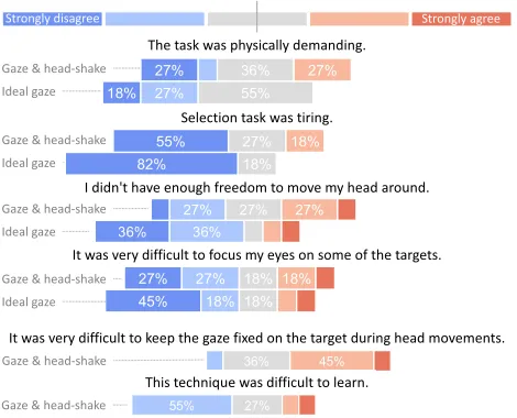
We also did a qualitative evaluation to assess the usability of our method as a selection technique particularly for the gaze & head-shake selection. The feedback of the ideal gaze task served us here as a baseline as the ideal gaze task re-quired only looking at the target for 1 second. The first two questions covered the overall perceived physical demand and tiredness (Figure 9). We can see that while the gaze & head-shake selection is physically more demanding and tir-ing than the ideal gaze task the majority of the participants were not affected by it (only 27% of the participants found
the gaze & head-shake selection physically demanding while only 18% of the participants thought the gaze & head-shake selection was tiresome). The responses to the third question show that some participants felt constrained in their head movement by the weight and the bulk of the VR headset. Those who responded negatively commented that they ex-perienced difficulties to perform large head shakes when the targets had high angular offsets. We also explored the difficulty of focusing on the main targets when they were partially occluded or when shown at very close distances. Based on the answers and participants’ comments, we un-derstood that a minority had problems focusing on partially occluded targets. Two extra questions were specific to the gaze & head-shake task. The answer to these questions show that 45% of the participants found it difficult to deliberately keep the gaze fixed on the target and move their head at the same time as required for our study. This high percentage could be a reason for the instability of the VG samples. Fi-nally, the majority of participants found the technique easy to learn.
Some of the participants later commented that the method could have been more natural when using smaller head move-ments and here in particular small head nods. One of the participants who had experiences in VR indicated that dis-ambiguation using head movements seemed to be more con-venient than moving hands or arms.
The task was physically demanding.
Selection task was tiring.
I didn't have enough freedom to move my head around.
It was very difficult to focus my eyes on some of the targets.
It was very difficult to keep the gaze fixed on the target during head movements.
This technique was difficult to learn.
Strongly disagree Strongly agree
Gaze & head-shake Ideal gaze
Gaze & head-shake Ideal gaze
Gaze & head-shake Ideal gaze
Gaze & head-shake Ideal gaze
Gaze & head-shake
[image:9.612.318.557.315.407.2]Gaze & head-shake
Figure 9: Participants’ responses to the questionnaires.
7 DISAMBIGUATION USING IMPLICIT HEAD
SHIFTS
We further explored the performance of the vergence and VOR-based methods by analyzing the data recorded during
the ideal gaze task. The results showed that despite our expec-tation, our method did not work properly using natural head shifts that occur when looking at targets (Figure 10). Overall, our VOR-based methods had significantly lower performance than the vergence method (F(3,30)=38.37,p =.000). For example, the mean selection rate forVGPAV was below 20% in the short-range condition which was 53% lower than the vergence method. The accuracy of the VOR-based methods were below 10% at target offsets 10◦ and they performed only 20% better for the angular offsets of 25◦and higher. No improvement was observed by increasing the angular offsets from 25◦to 45◦. The performance of the vergence method did not change compared to the gaze & head-shake task. We expect that the accuracy of the vergence method to be lower at higher angular offsets if no head shifts is made towards the target, however, we have not tested the effect of viewing angle on the vergence method in our study.
short-range wide-range
Depth condition 0
20 40 60 80 100
C
or
re
ct
se
le
ct
io
n
[%
]
VGPAV
VGPL
VGPR
[image:9.612.59.294.421.611.2]Vergence
Figure 10: Percentage of successful selection in the ideal gaze selection task.
The VGP samples in the ideal gaze task were taken during the first head movement made towards the target. One thing that we observed when looking at the data from the ideal gaze task was that in many trials gaze shift or vergence were still ongoing when the head velocity was at its maximum, making only the last 1/3 of the head shifts usable for depth estimation. As mentioned before, the VGP values were very unstable at head velocities lower than 50◦/secand there were only a few frames during the last 1/3 of the head shifts where the velocity was higher than that threshold even at extreme angular offsets. This can explain the very low performance for our method using implicit head shifts.
8 DISCUSSION
Our results show that our VOR depth estimation method can achieve similar accuracy as a vergence-based methods when resolving target ambiguity in 3D gaze interaction, in partic-ular for difficult cases where objects are close or partially occluded. Our results show that the VOR depth estimation even outperformed the vergence method in the wide-range scene condition by 18%. Since our method requires head
movements for estimating gaze depth, we see in particu-lar that it can be used in combination with other methods that combine gaze and head movements for interaction (e.g., [28, 31]) when used in 3D. One application example could be to resolve target ambiguity when continuous head move-ments are used to adjust continuous parameters of different objects in 3D (for example adjusting the volume of a TV that is partially occluded by another device).
The average selection time in our gaze & head-shake study was less than 600 ms which is comparable with 300-550 ms dwell time used in VR (e.g., [17, 34]), taking into account that dwell selection does not cope with the ambiguity problem. We can view a head-shake as an effective signal of intent to select, on which our VOR depth method piggy-backs at no additional interaction cost.
It is also worth to mention that we implemented the VOR depth estimation in VR, however, the principle is applicable to many other scenarios including real world and Augmented Reality. It can be used for depth estimation in head-mounted eye trackers when depth information is needed not continu-ously but on ad-hoc basis and beyond target disambiguation. This includes cases where non-continuous eye tracking is used to adapt the rendering of displays, e.g., for depth of field rendering or for highlighting objects in cluttered scenes and when hands-free is required. The latter has particular relevance for maintenance tasks as often demonstrated in Augmented Reality. Finally, we see a specific advantage of our approach in the fact that only a single eye needs to be tracked. This allows to estimate gaze depth in cases where vergence-based methods do not work such as monocular HMD designs similar to Google Glass.
Despite the theoretical potential of the VOR-based method, the results from our user study and the VG curves obtained from the depth calibration steps also showed that the pro-posed method was still very sensitive to noise which made the VG values less reproducible than the vergence value. We also identified a few other limitations of the proposed method and our implementation:
IPD approximation.We compared the proposed method with a vergence method that was not implemented using gaze rays or vergence angle but measured by subtracting the pupil positions of the left and the right eyes. This measure that we referred to as IPD signal was not the actual IPD measured in mm and was sensitive to the movements of the headset relative to the head because it was measured from two pupil positions obtained from two different image sensors. This could potentially affect the depth estimation result from the vergence method and perhaps explain the higher error at a depth 7 m for this method (Figure 8).
Signal synchronization.We found the VG calculation to be very sensitive to the synchronization issues between the eye and the head signals. Although the eye and head
signals used in our study were both obtained from the Tobii SDK, there were trials where the peaks of the two signals were not synchronized and we have seen an offset of 1-4 frames.
Non-VOR eye movements.As we discussed in the sub-jective evaluation, it was difficult for some people to maintain the gaze on the target during head shakes which resulted in non-VOR eye movements to be mixed with the VOR eye movements. This problem invalidates the key assumption of the proposed method.
Head shifts. Head rotations are not always pure rota-tions around an axis and are often combined with head shifts. Head shifts create eye movements when the gaze is fixed on a target and that affects the ratio between the eye and the head rotations.
No continuous depth estimation.Compared to the ver-gence based methods, the proposed method is not capable of estimating the depth on a continuous basis as it relies on VOR eye movements.
Future work could look at the effect of head shift as well as the changes in the rotation axis of the head. Small variations in these factors could be considered in the theory which can later be taken into account when calculating the VOR gain. This can potentially increase the depth estimation ac-curacy using the proposed method. In the future work, we would also study how the vergence method and the proposed method could be used together to complement each other.
9 CONCLUSIONS
In summary, this work has proposed a novel technique for depth estimation of the point of gaze in 3D which is based on the VOR eye movements. A user study showed the possibil-ity of using the proposed technique for resolving ambigupossibil-ity caused by the occlusion problem when target selection is done by gaze and head gestures. We showed that our method can achieve the same level of accuracy when compared to the methods that are only based on vergence. We further demon-strated that our method can be implemented by tracking only a single eye without relying on any gaze calibration.
10 ACKNOWLEDGEMENTS
This work is funded by the EPSRC project MODEM Grant No. EP/M006255/1. Tobias is partially supported by the Marsden Fund Council from Government funding, administered by the Royal Society of NZ.
REFERENCES
[1] Florian Alt, Stefan Schneegass, Jonas Auda, Rufat Rzayev, and Nora Broy. 2014. Using Eye-tracking to Support Interaction with Layered 3D Interfaces on Stereoscopic Displays. InProceedings of the 19th International Conference on Intelligent User Interfaces (IUI ’14). ACM, New York, NY, USA, 267–272. https://doi.org/10.1145/2557500.2557518
[2] Florian Alt, Stefan Schneegass, Jonas Auda, Rufat Rzayev, and Nora Broy. 2014. Using Eye-tracking to Support Interaction with Layered 3D Interfaces on Stereoscopic Displays. InProceedings of the 19th International Conference on Intelligent User Interfaces (IUI ’14). ACM, New York, NY, USA, 267–272. https://doi.org/10.1145/2557500.2557518 [3] Dora E Angelaki. 2004. Eyes on target: what neurons must do for the vestibuloocular reflex during linear motion.Journal of neurophysiology
92, 1 (2004), 20–35.
[4] F. Argelaguet and C. Andujar. 2009. Efficient 3D Pointing Selection in Cluttered Virtual Environments.IEEE Computer Graphics and Applica-tions29, 6 (Nov 2009), 34–43. https://doi.org/10.1109/MCG.2009.117 [5] Ferran Argelaguet, Carlos Andujar, and Ramon Trueba. 2008.
Over-coming Eye-hand Visibility Mismatch in 3D Pointing Selection. In
Proceedings of the 2008 ACM Symposium on Virtual Reality Software and Technology (VRST ’08). ACM, New York, NY, USA, 43–46. https: //doi.org/10.1145/1450579.1450588
[6] Richard Bates and Howell Istance. 2002. Zooming interfaces!: enhanc-ing the performance of eye controlled pointenhanc-ing devices. InProceedings of the fifth international ACM conference on Assistive technologies. ACM, 119–126.
[7] Brian C. Daugherty, Andrew T. Duchowski, Donald H. House, and Celambarasan Ramasamy. 2010. Measuring Vergence over Stereoscopic Video with a Remote Eye Tracker. InProceedings of the 2010 Symposium on Eye-Tracking Research & Applications (ETRA ’10). ACM, New York, NY, USA, 97–100. https://doi.org/10.1145/1743666.1743690 [8] S. Deng, J. Chang, S. Hu, and J. J. Zhang. 2017. Gaze Modulated
Disambiguation Technique for Gesture Control in 3D Virtual Objects Selection. In2017 3rd IEEE International Conference on Cybernetics (CYBCONF). 1–8. https://doi.org/10.1109/CYBConf.2017.7985779 [9] Andrew T. Duchowski, Donald H. House, Jordan Gestring, Robert
Congdon, Lech Świrski, Neil A. Dodgson, Krzysztof Krejtz, and Izabela Krejtz. 2014. Comparing Estimated Gaze Depth in Virtual and Physical Environments. InProceedings of the Symposium on Eye Tracking Re-search and Applications (ETRA ’14). ACM, New York, NY, USA, 103–110. https://doi.org/10.1145/2578153.2578168
[10] Andrew T. Duchowski, Eric Medlin, Anand Gramopadhye, Brian Mel-loy, and Santosh Nair. 2001. Binocular Eye Tracking in VR for Visual Inspection Training. InProceedings of the ACM Symposium on Virtual Reality Software and Technology (VRST ’01). ACM, New York, NY, USA, 1–8. https://doi.org/10.1145/505008.505010
[11] Andrew T. Duchowski, Brandon Pelfrey, Donald H. House, and Rui Wang. 2011. Measuring Gaze Depth with an Eye Tracker During Stereoscopic Display. InProceedings of the ACM SIGGRAPH Symposium on Applied Perception in Graphics and Visualization (APGV ’11). ACM, New York, NY, USA, 15–22. https://doi.org/10.1145/2077451.2077454 [12] N. Elmqvist and P. Tsigas. 2008. A Taxonomy of 3D Occlusion Man-agement for Visualization. IEEE Transactions on Visualization and Computer Graphics14, 5 (Sept 2008), 1095–1109. https://doi.org/10. 1109/TVCG.2008.59
[13] David Fono and Roel Vertegaal. 2005. EyeWindows: evaluation of eye-controlled zooming windows for focus selection. InProceedings of the SIGCHI conference on Human factors in computing systems. ACM, 151–160.
[14] Peter A Gorry. 1990. General least-squares smoothing and differentia-tion by the convoludifferentia-tion (Savitzky-Golay) method.Analytical Chemistry
62, 6 (1990), 570–573.
[15] Esteban Gutierrez Mlot, Hamed Bahmani, Siegfried Wahl, and Enkele-jda Kasneci. 2016. 3D Gaze Estimation Using Eye Vergence. In Pro-ceedings of the International Joint Conference on Biomedical Engineer-ing Systems and Technologies (BIOSTEC 2016). SCITEPRESS - Sci-ence and Technology Publications, Lda, Portugal, 125–131. https: //doi.org/10.5220/0005821201250131
[16] Dan Witzner Hansen, Henrik HT Skovsgaard, John Paulin Hansen, and Emilie Møllenbach. 2008. Noise tolerant selection by gaze-controlled pan and zoom in 3D. InProceedings of the 2008 symposium on Eye tracking research & applications. ACM, 205–212.
[17] John Paulin Hansen, Vijay Rajanna, I. Scott MacKenzie, and Per Bæk-gaard. 2018. A Fitts’ Law Study of Click and Dwell Interaction by Gaze, Head and Mouse with a Head-mounted Display. In Proceed-ings of the Workshop on Communication by Gaze Interaction (CO-GAIN ’18). ACM, New York, NY, USA, Article 7, 5 pages. https: //doi.org/10.1145/3206343.3206344
[18] C. Hennessey* and P. Lawrence. 2009. Noncontact Binocular Eye-Gaze Tracking for Point-of-Gaze Estimation in Three Dimensions. IEEE Transactions on Biomedical Engineering56, 3 (March 2009), 790–799. https://doi.org/10.1109/TBME.2008.2005943
[19] https://www.tobiipro.com/product-listing/vr integration/. 2018 (ac-cessed Aug 1, 2018). .
[20] Robert JK Jacob. 1991. The use of eye movements in human-computer interaction techniques: what you look at is what you get.ACM Trans-actions on Information Systems (TOIS)9, 2 (1991), 152–169.
[21] Shahram Jalaliniya, Diako Mardanbegi, and Thomas Pederson. 2015. MAGIC Pointing for Eyewear Computers. InProceedings of the 2015 ACM International Symposium on Wearable Computers (ISWC ’15). ACM, New York, NY, USA, 155–158. https://doi.org/10.1145/2802083. 2802094
[22] J. Ki and Y. Kwon. 2008. 3D Gaze Estimation and Interaction. In2008 3DTV Conference: The True Vision - Capture, Transmission and Display of 3D Video. 373–376. https://doi.org/10.1109/3DTV.2008.4547886 [23] Konstantin Klamka, Andreas Siegel, Stefan Vogt, Fabian Göbel, Sophie
Stellmach, and Raimund Dachselt. 2015. Look & Pedal: Hands-free Navigation in Zoomable Information Spaces Through Gaze-supported Foot Input. InProceedings of the 2015 ACM on International Conference on Multimodal Interaction (ICMI ’15). ACM, New York, NY, USA, 123– 130. https://doi.org/10.1145/2818346.2820751
[24] R. Kopper, F. Bacim, and D. A. Bowman. 2011. Rapid and accurate 3D selection by progressive refinement. In2011 IEEE Symposium on 3D User Interfaces (3DUI). 67–74. https://doi.org/10.1109/3DUI.2011. 5759219
[25] Yong-Moo Kwon, Kyeong-Won Jeon, Jeongseok Ki, Qonita M Sha-hab, Sangwoo Jo, and Sung-Kyu Kim. 2006. 3D Gaze Estimation and Interaction to Stereo Dispaly.IJVR5, 3 (2006), 41–45.
[26] Mikko Kytö, Barrett Ens, Thammathip Piumsomboon, Gun A. Lee, and Mark Billinghurst. 2018. Pinpointing: Precise Head- and Eye-Based Target Selection for Augmented Reality. InProceedings of the 2018 CHI Conference on Human Factors in Computing Systems (CHI ’18). ACM, New York, NY, USA, Article 81, 14 pages. https://doi.org/10.1145/ 3173574.3173655
[27] Radosław Mantiuk, Bartosz Bazyluk, and Anna Tomaszewska. 2011. Gaze-Dependent Depth-of-Field Effect Rendering in Virtual Environ-ments. InSerious Games Development and Applications, Minhua Ma, Manuel Fradinho Oliveira, and João Madeiras Pereira (Eds.). Springer Berlin Heidelberg, Berlin, Heidelberg, 1–12.
[28] Diako Mardanbegi, Dan Witzner Hansen, and Thomas Pederson. 2012. Eye-based Head Gestures. InProceedings of the Symposium on Eye Tracking Research and Applications (ETRA ’12). ACM, New York, NY, USA, 139–146. https://doi.org/10.1145/2168556.2168578
[29] Olivier Mercier, Yusufu Sulai, Kevin Mackenzie, Marina Zannoli, James Hillis, Derek Nowrouzezahrai, and Douglas Lanman. 2017. Fast Gaze-contingent Optimal Decompositions for Multifocal Displays. ACM Trans. Graph.36, 6, Article 237 (Nov. 2017), 15 pages. https://doi.org/ 10.1145/3130800.3130846
[30] Susan M. Munn and Jeff B. Pelz. 2008. 3D Point-of-regard, Position and Head Orientation from a Portable Monocular Video-based Eye
Tracker. InProceedings of the 2008 Symposium on Eye Tracking Research & Applications (ETRA ’08). ACM, New York, NY, USA, 181–188. https: //doi.org/10.1145/1344471.1344517
[31] Tomi Nukarinen, Jari Kangas, Oleg Špakov, Poika Isokoski, Deepak Akkil, Jussi Rantala, and Roope Raisamo. 2016. Evaluation of Head-Turn: An Interaction Technique Using the Gaze and Head Turns. In
Proceedings of the 9th Nordic Conference on Human-Computer Inter-action (NordiCHI ’16). ACM, New York, NY, USA, Article 43, 8 pages. https://doi.org/10.1145/2971485.2971490
[32] Jason Orlosky, Takumi Toyama, Daniel Sonntag, and Kiyoshi Kiyokawa. 2016. The Role of Focus in Advanced Visual Interfaces.KI - Künstliche Intelligenz30, 3 (01 Oct 2016), 301–310. https://doi.org/ 10.1007/s13218-015-0411-y
[33] Thies Pfeiffer, Marc Erich Latoschik, and Ipke Wachsmuth. 2008. Eval-uation of binocular eye trackers and algorithms for 3D gaze interaction in virtual reality environments.JVRB-Journal of Virtual Reality and Broadcasting5, 16 (2008).
[34] Vijay Rajanna and John Paulin Hansen. 2018. Gaze typing in virtual reality: impact of keyboard design, selection method, and motion. In
Proceedings of the Tenth Biennial ACM Symposium on Eye Tracking Research and Applications (ETRA’18).
[35] Stephan Reichelt, Ralf Häussler, Gerald Fütterer, and Norbert Leister. 2010. Depth cues in human visual perception and their realization in 3D displays. InThree-Dimensional Imaging, Visualization, and Display 2010 and Display Technologies and Applications for Defense, Security, and Avionics IV, Vol. 7690. International Society for Optics and Photonics, 76900B.
[36] Oleg Špakov. 2011. Comparison of gaze-to-objects mapping algo-rithms. InProceedings of the 1st Conference on Novel Gaze-Controlled Applications. ACM, 6.
[37] A. Steed. 2006. Towards a General Model for Selection in Virtual Environments. In3D User Interfaces (3DUI’06). 103–110. https://doi. org/10.1109/VR.2006.134
[38] Anthony Steed and Chris Parker. 2004. 3D selection strategies for head tracked and non-head tracked operation of spatially immersive displays. In8th International Immersive Projection Technology Workshop. 13–14.
[39] Sophie Stellmach and Raimund Dachselt. 2012. Look & touch: gaze-supported target acquisition. InProceedings of the SIGCHI Conference on Human Factors in Computing Systems. ACM, 2981–2990. [40] Vildan Tanriverdi and Robert JK Jacob. 2000. Interacting with eye
movements in virtual environments. InProceedings of the SIGCHI conference on Human Factors in Computing Systems. ACM, 265–272. [41] E Viirre, D Tweed, K Milner, and T Vilis. 1986. A reexamination of the
gain of the vestibuloocular reflex. Journal of Neurophysiology56, 2 (1986), 439–450.
[42] Rui I. Wang, Brandon Pelfrey, Andrew T. Duchowski, and Donald H. House. 2014. Online 3D Gaze Localization on Stereoscopic Displays.
ACM Trans. Appl. Percept.11, 1, Article 3 (April 2014), 21 pages. https: //doi.org/10.1145/2593689
[43] Martin Weier, Thorsten Roth, André Hinkenjann, and Philipp Slusallek. 2018. Predicting the Gaze Depth in Head-mounted Displays Using Mul-tiple Feature Regression. InProceedings of the 2018 ACM Symposium on Eye Tracking Research & Applications (ETRA ’18). ACM, New York, NY, USA, Article 19, 9 pages. https://doi.org/10.1145/3204493.3204547