RESEARCH ARTICLE
TRANSIENT STABILITY ENHANCEMENT OF REAL TIME SYSTEM USING ETAP
*1Er. Sujatha, S.,
2Dr. Anitha, R.,
3Dr. Selvan, P. and
4Er. Selvakumar, S.
1
Assistant Engineer, TNEB, Karur, Tamilnadu, India
2
Department of EEE, Institute Road and Transport Technology, Erode, Tamilnadu, India
3Department of EEE, Erode Sengunthar Engineering College, Erode, Tamilndu, India
4
Design Engineer, ABB Global Industries, Chennai, Tamilnadu, India
ARTICLE INFO ABSTRACT
The modeling of the real time system with Static VAR Compensator (SVC) using ETAP software is presented in this paper. The system is analyzed under severe disturbance to study the transient behavior by simulating three phase to ground fault at particular bus. To enhance the transient stability of the system, SVC is inserted and tested to show the effect of the same on the transient stability under severe disturbance. The potential application of SVC on the improvement of voltage profile of the various buses and reduction in rotor angle oscillation of the generator is evaluated from the implementation results.
Copyright © 2014 Er. Sujatha et al. This is an open access article distributed under the Creative Commons Attribution License, which permits unrestricted use, distribution, and reproduction in any medium, provided the original work is properly cited.
INTRODUCTION
Transient stability evaluation focuses on the reactive power flow of the power system in response to a fault. In transient stability prediction, the progress of the power system transient due to occurrence of disturbance is to be monitored. The key factor in transient stability prediction is based on the convergence and divergence of transient swings. The problem is formulated as the insertion of SVC in real time system that is to be analyzed using ETAP simulation software for enhancing the transient stability. SVCs, with an auxiliary injection of a suitable signal, can significantly improve the dynamic stability performance of a power system (Byerly et al., 1982; Hammad 1986) presented a fundamental analysis of the application of SVC for enhancing the power system stability. Also, the enhancement of low frequency oscillation damping via SVC has been analyzed (Padiyar and Varma 1991; Zhou 1993; De Oliveira 1994; Messina et al., 1999). The SVC enhances the system damping of local as well as inter-area oscillation modes. Ref (Messina and Barocio 2003) studied the nonlinear model interaction in stressed power systems with multiple SVC voltage support. It is observed that SVC controller can significantly influence nonlinear system behavior especially under high-stress operating conditions and increased SVC gains (8).The general representation of SVC is represented in the Fig.1.1
*Corresponding author: Er. Sujatha, S.
Assistant Engineer, TNEB, Karur, Tamilnadu, India.
MODELING OF SVC
[image:1.595.331.535.612.750.2]SVCs, with an auxiliary injection of a suitable signal, can significantly improve the dynamic stability performance of a power system (Byerly et al., 1982; Hammad 1986) presented a fundamental analysis of the application of SVC for enhancing the power system stability. Also, the improvement of low frequency oscillation damping via SVC has been analyzed (Padiyar and Varma 1991). The SVC improve the system damping of local as well as inter-area oscillation modes.SVC model shown in Figure 2.1, used to improve the transient stability of the real time system considered, has been modeled in ETAP 12.5
Figure 1.1. SVC employing TSC and TCR
ISSN: 0975-833X
International Journal of Current Research Vol. 6, Issue, 04, pp.6154-6159, April, 2014
INTERNATIONAL JOURNAL OF CURRENT RESEARCH
Article History:
Received 07thJanuary, 2013 Received in revised form 07thFebruary, 2014
Accepted 15thMarch, 2014
Published online 23rdApril, 2014
Key words:
Exciter, Faults, FACTS, SVC, Real time system, Transient stability.
RESEARCH ARTICLE
TRANSIENT STABILITY ENHANCEMENT OF REAL TIME SYSTEM USING ETAP
*1Er. Sujatha, S.,
2Dr. Anitha, R.,
3Dr. Selvan, P. and
4Er. Selvakumar, S.
1
Assistant Engineer, TNEB, Karur, Tamilnadu, India
2
Department of EEE, Institute Road and Transport Technology, Erode, Tamilnadu, India
3Department of EEE, Erode Sengunthar Engineering College, Erode, Tamilndu, India
4
Design Engineer, ABB Global Industries, Chennai, Tamilnadu, India
ARTICLE INFO ABSTRACT
The modeling of the real time system with Static VAR Compensator (SVC) using ETAP software is presented in this paper. The system is analyzed under severe disturbance to study the transient behavior by simulating three phase to ground fault at particular bus. To enhance the transient stability of the system, SVC is inserted and tested to show the effect of the same on the transient stability under severe disturbance. The potential application of SVC on the improvement of voltage profile of the various buses and reduction in rotor angle oscillation of the generator is evaluated from the implementation results.
Copyright © 2014 Er. Sujatha et al. This is an open access article distributed under the Creative Commons Attribution License, which permits unrestricted use, distribution, and reproduction in any medium, provided the original work is properly cited.
INTRODUCTION
Transient stability evaluation focuses on the reactive power flow of the power system in response to a fault. In transient stability prediction, the progress of the power system transient due to occurrence of disturbance is to be monitored. The key factor in transient stability prediction is based on the convergence and divergence of transient swings. The problem is formulated as the insertion of SVC in real time system that is to be analyzed using ETAP simulation software for enhancing the transient stability. SVCs, with an auxiliary injection of a suitable signal, can significantly improve the dynamic stability performance of a power system (Byerly et al., 1982; Hammad 1986) presented a fundamental analysis of the application of SVC for enhancing the power system stability. Also, the enhancement of low frequency oscillation damping via SVC has been analyzed (Padiyar and Varma 1991; Zhou 1993; De Oliveira 1994; Messina et al., 1999). The SVC enhances the system damping of local as well as inter-area oscillation modes. Ref (Messina and Barocio 2003) studied the nonlinear model interaction in stressed power systems with multiple SVC voltage support. It is observed that SVC controller can significantly influence nonlinear system behavior especially under high-stress operating conditions and increased SVC gains (8).The general representation of SVC is represented in the Fig.1.1
*Corresponding author: Er. Sujatha, S.
Assistant Engineer, TNEB, Karur, Tamilnadu, India.
MODELING OF SVC
SVCs, with an auxiliary injection of a suitable signal, can significantly improve the dynamic stability performance of a power system (Byerly et al., 1982; Hammad 1986) presented a fundamental analysis of the application of SVC for enhancing the power system stability. Also, the improvement of low frequency oscillation damping via SVC has been analyzed (Padiyar and Varma 1991). The SVC improve the system damping of local as well as inter-area oscillation modes.SVC model shown in Figure 2.1, used to improve the transient stability of the real time system considered, has been modeled in ETAP 12.5
Figure 1.1. SVC employing TSC and TCR
ISSN: 0975-833X
International Journal of Current Research Vol. 6, Issue, 04, pp.6154-6159, April, 2014
INTERNATIONAL JOURNAL OF CURRENT RESEARCH
Article History:
Received 07thJanuary, 2013 Received in revised form 07thFebruary, 2014
Accepted 15thMarch, 2014
Published online 23rdApril, 2014
Key words:
Figure 2.1 Modeling of SVC
MODELING OF REAL TIME SYSTEM
Test system having a peak demand of 50 MW with a cogeneration plant of 35 MW is considered. Considering the peak load of 50 MW, the test system receives the power supply at 220 kV. Further it is stepped down to 110 kV through two 100 MVA, 220 / 110 kV transformers. 35 MW generator is modeled using ETAP with the technical parameters shown in Table 3.1.
Table 3.1. 35 Mw Generator Parameters
Variable Description Data
MVA rating 43.75
MW rating 35
Rated voltage in kV 11
Ra Armature resistance in p.u. 0.004593
X2 Negative sequence reactance in p.u. 0.149
X0 Zero sequence reactance in p.u. 0.066
Xd Direct axis reactance in p.u. 2.036
Xd' Direct axis transient reactance in p.u. 0.237
Xd'' Direct axis sub - transient reactance in p.u. 0.185
Xq Quadrature axis reactance in p.u. 1.8
Xq' Quadrature axis transient reactance in p.u. 0.33
Xq'' Quadrature axis sub–transient reactance in p.u. 0.1678
Tdo' Direct axis open circuit transient time constant in
p.u.
4.902
Tdo" Direct axis open circuit sub–transient time
constant in p.u.
0.017
Tqo' Quadrature axis open circuit transient time
constant in p.u.
0.533
Tqo" Quadrature axis open circuit sub–transient time
constant in p.u.
0.1
H Inertia constant (Generator + Exciter) 3
Winding connection Y grounded
through NGT
The generator is connected to the transformer of 40/45 MVA, 110/11 kV, ONAN / ONAF with 12.5% impedance on its own base. This transformer has an OCTC with 17 taps (-15% to 7.5%). Major loads like Electric Arc Furnace (EAF), Ladle Refining Furnace (LRF) and Rolling mill are highly fluctuating in nature and hence considered with one dedicated transformer of 35/40 MVA, 110/33 kV, ONAN/ONAF with 10% impedance on 40 MVA base. This transformer has an OCTC with 9 taps (-15% to 5%). Other additional auxiliary supply for process, power plant, lighting loads and small power loads are grouped together and fed from 11 kV via 15 MVA, 110/11 kV, ONAN with 10% impedance on its own base. This transformer also has an OCTC with 9 taps (-15% to 5%). The system uses 220 kV, 110 kV, 33 kV, 11 kV, 6.6 kV and 415 V systems for the efficient operation.
[image:2.595.310.555.108.216.2]Transformer data (rated MVA, rated HV/LV voltage, % impedance) considered is given in Table 3.2.
Table 3.2. Transformer Data
R a t e d M V A R a t e d H V / L V % i m p e d a n c e
1 0 0 2 2 0 / 1 1 0 1 0
4 0 1 1 0 / 3 3 1 0
4 5 1 1 / 1 1 0 1 2 . 5
6 . 3 1 1 / 6 . 6 7 . 1 5
1 5 1 1 0 / 1 1 1 0
1 . 2 5 1 1 / 0 . 4 3 3 6
3 1 1 / 0 . 4 3 3 6
0 . 5 1 1 / 0 . 4 3 3 6
6 . 3 1 1 / 6 . 9 6
0 . 3 1 5 1 1 / 0 . 4 3 3 6
[image:2.595.314.555.301.553.2]Detailed system modeling is of prime importance for carrying out any system study. The block diagrams of automatic voltage regulator (AVR) and turbine governor (TG), shown in Figures 3.1 and 3.2 respectively, have been modeled using ETAP for 35 MW generator. The parameter related to the AVR and TG are listed in Tables 3.3 and 3.4 respectively.
[image:2.595.32.290.340.565.2]Figure 3.1. Block diagram of AVR for 35 MW Generator
[image:2.595.310.555.594.747.2]Figure 3.2. Block diagram of TG for 35 MW generator
Table 3.3. Avr Data for 35 Mw Generator
Variable Description Data
Trec Input rectifier time constant in s 0.02
Ta Amplifier time constant in s 0.02
Te Exciter time constant in s 0.6
Tf1 Regulator stabilizing circuit time constant1in s 1.0
Tf2 Regulator stabilizing circuit time constant2 in s 0.1
ka Amplifier gain 100
ke Exciter gain 1.0
Kf Regulator stabilizing circuit gain 0.01
Vse1 Saturation function at 0.75 times maximum
field voltage
0.4
Vse2 Saturation function at maximum field voltage 0.7
Vrmax Maximum amplifier voltage 4.3
Vrmin Minimum amplifier voltage -4.3
Efdmax Maximum field voltage 4.3
This real time system is modeled using ETAP simulation software and the corresponding single line diagram is shown in Figure 3.3.
[image:3.595.310.552.234.353.2]Figure 3.3. Single line diagram of real time system
Table 3.4. Turbine Governor Data For 35 Mw Generator
SIMULATION RESULTS
The ETAP software is used to simulate the real time system yield validated results. To simulate the real time system ,models have been developed for each element and implemented in the dedicated power system simulation tool ETAP which provides the ability to simulate load flow study, short circuit study and Transient events in the same software environment. The ETAP simulation tool therefore has a dedicated model for generators which take into account the current displacement in the rotor, slip and short circuit analysis curves. Also models of synchronous machines, transformers, bus bars, grid models, Transmission lines etc are provided.
TRANSIENT ANALYSIS a. With out disturbances
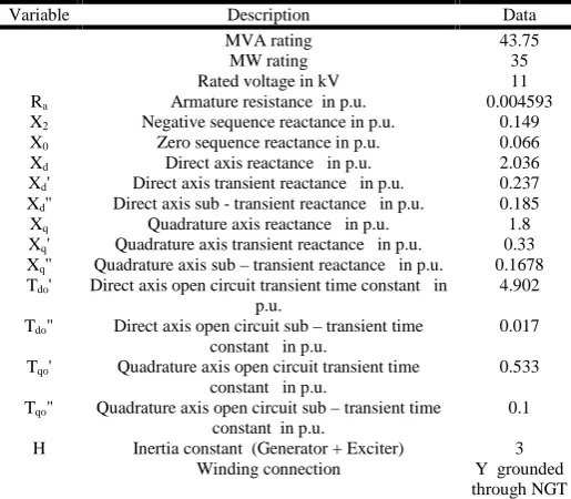
The real time system was kept as ideal and the simulation results are presented here. The power generated by the generator remains constant even if the loads of the system can vary is represented in the 4.1
Figure 4.1 Real power P of the Generator
[image:3.595.53.264.381.479.2]The given loads,the generator has to generate 20 MVAr to maintain its terminal voltage is depicted in the Figure 4.2.
Figure 4.2 Reactive power Q of the Generator
[image:3.595.311.552.413.500.2]The generator has the capability to adjust the reactive power and to maintain the voltage is represented in the Figure 4.3
Figure 4.3 Generator bus (22) voltage
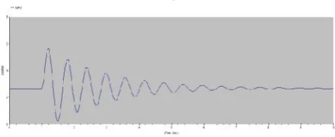
[image:3.595.311.555.581.678.2]Since the 110 k V bus is considered as slack bus for the load flow study,the voltage and angle of the bus remains constant is represented in the Figure 4.4.
Figure 4.4 110 kV Bus (5) voltage
The 33 k V bus receives power from 110 kV grid through two winding transformer. Due to the leakage reactance of the transformer the voltage at the 33 kV bus starts falling is depicted in the Fig.4.5.
Variable Description Data
Droop 0.05
Pmax Maximum power limit 1.0
Pmin Minimum power limit 0.1
Cmax Rate of valve opening 0.1
Cmin Rate of valve closing -1.0
T1 Phase compensation 1 0.1
T2 Phase compensation 2 0.3
T3 Servo time constant 0.4
Figure 4.5. 33 kV Bus(10) voltage
[image:4.595.318.557.51.152.2]11 kV bus receives the power from 110 k V grid through two winding transformer.In that real time system the generator auxiliary,EAF auxiliary,Oxygen plant loads are fed by the given transformer.The terminal voltage is 106.44 % is depicted in the Figure 4.6.
Figure 4.6. 11 kV Bus(29) voltage
b. With disturbances
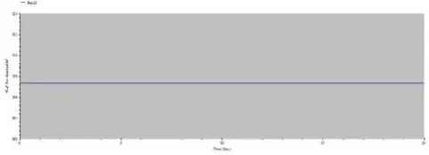
Here the real time system was tested by creating the three phase to ground fault at the 11 kV bus(29) and the simulation results were produced. Figure 4.7 describes the generator will oscillate whenever there is a fault in network. The oscillation of generators is basically measured with respect to infinite bus(grid) which is represented as slack bus. The oscillation level of the generator depends on the disturbances severity and its time duration. A 100 ms duration of the three phase fault at 11 kV bus leads the generator to oscillate from 2.4 to 6 degree, whereas at the steady state condition it is 2.3 degrees with respect to grid.
Figure 4.7. Swing curve of the generator at fault condition
Figure 4.8 describes the real power generation and reactive power generation of the generator when there is a fault at 11 kV bus. It indicates the oscillation of real power of the generator that varies from 27 MW to 43 MW.
Figure 4.8 Real power P of the Generator
[image:4.595.313.556.241.335.2]The reactive power of the generator drastically increases from 22 MVAr to 76 MVAr during the fault without any time delay because the exciter characteristics are fast in nature is represented in the Figure 4.9.
[image:4.595.42.283.262.358.2]Figure 4.9 Reactive power Q of the Generator The severity of the dip in the voltage at any bus is directly related to the distance from the fault location.Since,110 k V grid bus is far away from the fault location, hence the voltage reduced from 100 % during fault and recovers back to normal after the clearance of the fault is described in the Figure.4.10
Figure 4.10. 110 kV Bus (5)voltage
[image:4.595.315.555.438.533.2] [image:4.595.45.284.567.665.2]The 33 kV bus is far away from the faulty 11 kV bus and two winding transformer impedances exist between the two buses, the voltage reduction is severe during fault and recovers back to normal after clearance of the fault is represented in the Figure 4.11
[image:4.595.311.556.634.727.2]Since the fault is at this bus,the voltage is zero during fault and recovers back to the normal after clearance of the fault is represented in the Figure 4.12
Figure 4.12 11 kV Bus (29)voltage
c. WITH SVC
[image:5.595.48.284.356.578.2]The SVC is placed at 33 kV bus and fault is created at the 11 kV bus and the simulation results were produced here.SVC at 33 kV bus slightly improves the transient stability by reducing the oscillation represents the figure 4.13. The ability of the SVC at 33 kV bus significantly contributes the reactive power and improve the voltage profile of the 110 kV ,33 kV , and 11 kV bus respectively, which prevents the large motors connected to these buses to stall were represented the figure.
Figure 4.13 Swing curve of the generator
Figure 4.14 Real power P of the Generator
Conclusion
The fluctuating /non-linear nature of the load present in the real time system, SVC is considered to maintain the voltage profile and to enhance the transient stability of the system. Various cases are simulated and the response of the system are presented. Modeling of real time system with SVC is presented .SVC is modeled using ETAP for enhancing the transient stability of the system. From the transient stability analysis, SVC at 33 kV Bus improves the voltage profile of the real time system for the three phase to ground fault. However the impact of SVC on damping the rotor angle oscillation of the generator is not so effective for the system considered.
REFERENCES
Abido, M A,2009. “Power system stability enhancement using FACTS Controllers: A review”, The Arabian Journal for Science and Engineering, Vol. 34, No. 2B, pp. 153-172. Byerly, R. T. D., Poznaniak, T. and Taylor, E. R. 1982.
“Static Reactive Compensation for Power Transmission
System”, IEEE Transaction. PAS-101, pp. 3998–4005.
Byerly, R. T. D., Poznaniak, T.and Taylor, E. R. 1982. “Static Reactive Compensation for Power Transmission System”, IEEE Transaction. PAS-101, pp. 3998–4005.
Chang, C. S. and Qizhi, Y. 1999. “Fuzzy Bang–Bang Control
of Static VAR Compensators for Damping System-Wide
Low-Frequency Oscillations”, Electric Power Systems
Research, Vol. 49, pp. 45–54.
Chang, J. and Chow, J. 1997. “TimeOptimal Series Capacitor
Control for Damping Interarea Modes in Interconnected
Power Systems”, IEEE Trans. PWRS, Vol. 12, No. 1, pp.
215–221.
Chen, X., Pahalawaththa, N., Annakkage, U. and Kumble, C.
1995. “Controlled Series Compensation for Improving the Stability of Multimachine Power Systems”, IEE Proc.,
Part-C, Vol. 142, pp. 361–366.
Chintu Rza Makkar and Lillie Dewan, 2010. “Transient Stability Enhancement using Robust FACTS controllers– A Brief Tour”, Canadian Journal on Electrical & Electronics Engineering Vol. 1, No. 7, pp. 150-155.
Dai, X., Liu, J., Tang, Y., Li, N. and Chen, H. 1998. “Neural
Network αth-Order Inverse Control of Thyristor Controlled
Series Compensator”, Electric Power Systems Research,
Vol. 45, pp. 19–27.
Dash, P. K. Sharaf, A.M. and Hill, E. F. 1989. “An Adaptive
Stabilizer for Thyristor Controlled Static VAR
Compensators for Power Systems”, IEEE Trans. PWRS,
Vol. 4, No. 2, pp. 403–410.
Dash, P. K.,Mishra, S. and Liew, A. C. 1995. “Fuzzy-Logic Based VAR Stabilizer for Power System Control”, IEE
Proc. Genet. Transm. Distrib., Vol. 142, No. 6, pp. 618–
624.
Dash, P. K., Panda, P. C., Sharaf, A. M. and Hill, E. F. 1987.
“Adaptive Controller for Static Reactive Power
Compensators in Power Systems”, IEE Proc. Part-C, Vol.
134, No. 3, pp. 256–264.
Dash, P. K., Samantary, S.R. and Ganapathi Panda. 2007.
“Fault Classification and Section Identification of an
Advanced Series–Compensated Transmission Line Using
Support vector machine”, IEEE Trans. Power Delivery,
Vol. 22, No. 1, pp. 67-73.
De Oliveira, S.E.M. 1994. “Synchronizing and damping torque coefficients and power system steady-state stability as affected by static VAr compensators”, IEEE Transaction on Power Systems, Vol. 9, No. 1, pp. 109-119.
DeMello, F. and Concordia, C. 1969. “Concepts of
Synchronous Machine Stability as Affected by Excitation
Control”,IEEE Transaction. PAS, Vol. 88, pp. 316–329.
Eleschova, Z., Smitkova, M. and Belan, A. 2010. “Evaluation
of Power System Transient Stability and Definition of the Basic Criterion”, International Journal of Energy, Vol. 4,
No. 1, pp. 9-16.
El-Saady, G., El-Sadek, M. Z. and Abo-El-Saud, M. 1998.
[image:5.595.48.283.359.450.2]System Static VAR Stabilizer”, Electric Power Systems
Research, Vol. 45, No. 1, pp. 1–11.
Girgis A. A., Sallam, A. A. and El-din, A. K. 1998. “An adaptive protection scheme foe advanced series compensated (ASC) Transmission line,” IEEE Transaction. Power Del., Vol. 13, No. 1, pp. 414–420.
Gyugi L., 1988. “Power Electronics in Electric Utilities Static Var Compensators”, IEEE Proceedings, Vol. 76, No. 4, pp. 483-494.
Gyugi L., 1998. “Converter Based FACTS Controllers”,
Institution of Electrical Engineers, pp. 1-11.
Hammad, A. E. 1986. “Analysis of Power System Stability Enhancement by Static VAR Compensators”, IEEE Trans. PWRS, Vol. 1, No. 4, pp. 222–227.
Hingorani N.G. and L. Gyugyi, 1999. “Understanding FACTS”, IEEE press.
Messina, A. R. and Barocio, E. 2003. “Nonlinear Analysis of Interarea Oscillations: Effect of SVC Voltage Support”,
Electric Power Systems Research, Vol. 64, No. 1, pp. 17– 26.
Messina, A. R., Begovich, O. and Nayebzadeh, M. 1999. “Analytical Investigation of the Use of Static VAR Compensators to Aid Damping of Interarea Oscillations”,
Electric Power Systems Research, Vol. 51, pp. 199–210. Padiyar, K.R. and Varma, R.K. 1991.“Damping Torque
Analysis of Static VAR System Controllers”, IEEE Transactions on Power Systems, Vol. 6, No. 2. pp.
458-465.
Zhou, E.Z. 1993. “Application of Static Var Compensators to Increase Power System damping”, IEEE Transactions on Power Systems, Vol. 8, No. 2, pp. 655-661.