Original citation:
Li, Dezhi, Chrysanthou, Andreas, Patel, Imran and Williams, Geraint J. (2016) Self-piercing riveting - a review. Working Paper. Coventry: University of Warwick WMG. (Unpublished) Permanent WRAP URL:
http://wrap.warwick.ac.uk/79605
Copyright and reuse:
The Warwick Research Archive Portal (WRAP) makes this work by researchers of the University of Warwick available open access under the following conditions. Copyright © and all moral rights to the version of the paper presented here belong to the individual author(s) and/or other copyright owners. To the extent reasonable and practicable the material made available in WRAP has been checked for eligibility before being made available.
Copies of full items can be used for personal research or study, educational, or not-for-profit purposes without prior permission or charge. Provided that the authors, title and full bibliographic details are credited, a hyperlink and/or URL is given for the original metadata page and the content is not changed in any way.
A note on versions:
The version presented here is a working paper or pre-print that may be later published elsewhere. If a published version is known of, the above WRAP url will contain details on finding it.
Self-Piercing Riveting-A review
Dezhi Li1*, Andreas Chrysanthou2, Imran Patel2, Geraint Williams1
1WMG, University of Warwick, Coventry, CV4 7AL, UK
2School of Engineering and Technology, University of Hertfordshire, Hatfield, AL10 9AB, UK
*Corresponding author, e-mail:[email protected]
Abstract
Self-Piercing Riveting (SPR) is a cold mechanical joining process used to join two or more sheets of
materials by driving a semitubular rivet piercing through the top sheet or the top and middle sheets
and subsequently lock into the bottom sheet under the guidance of a suitable die. SPR was originated
half century ago, but it only had significant progress in the last 25 years due to the requirement of
joining lightweight materials, such as aluminium alloy structures, aluminium-steel structures and
other mixed material structures, from the automotive industry. Compared with other conventional
joining methods, SPR has a lot of advantages including no predrilled holes required, no fume, no
spark and low noise, no surface treatment required, ability to join multilayer materials and mixed
materials, and ability to produce joint with high static and fatigue strengths etc. This publication
reviews research investigations that have been conducted in the area of self-piercing riveting. The
process is described and the effects of the process parameters are discussed. Mechanical properties
including static strength, fatigue and crash behaviour are reviewed. Corrosion behaviour is also
addressed, while reliable methods for accurate behaviour prediction, process monitoring and
non-destructive testing have been identified as the main challenges.
Keywords: Self-Piercing Riveting; Process parameters; Structure joining; Mechanical strength; Finite
element modelling
1. Introduction
Self-Piercing Riveting (SPR) originated in the 1960’s, but was only significantly developed in the
past 25 years due to requirements from the automotive industry. In 1972, Hulbert compared SPR with
traditional riveting, and the main difference between SPR and traditional riveting is that the former
does not require pre-punch and alignment [1]. In 1975, a SPR system the Bifurcated & Tubular Rivet
without pre-punched holes [2]. In 1976, Gausden and Gunn [3] from the Bifurcated & Tubular Rivet
Co. Ltd. discussed the development of SPR, its advantages, suitable materials, and some applications.
They also demonstrated that the SPR process could be automated. However, significant SPR process
development, wide applications and research interest of the SPR process was not emerged until the
requirement to join lightweight aluminium alloy structures. The drive to reduce the weight of the
automotive vehicle body has led to the use of aluminium alloys to replace some traditional mild steel.
To join aluminium alloys and mixed material structures, traditional resistance spot welding met some
difficulties and problems, and as a result SPR was chosen as an alternative joining process. In 1983,
Sunday [4] reviewed the process and advantages of SPR, the application of SPR in the automotive
industry, and compared the strength of the SPR joints with that of the traditional spot welded joints. In
1992, Patrick and Sharp [5] compared various processes, including SPR, for joining automotive
aluminium body structures, from various aspects, including minimum flange width, minimum joint
space, process speed and cost etc. In the same year, Edwards [6] also introduced SPR (also referred to
Pierce-&Roll riveting), as an alternative joining process for spot welding. In 1993, Doo [7]
summarized the process and the developments of Henrob SPR system and discussed its application in
the automotive industry. Hill [8] reviewed the SPR process and equipment for automotive
applications. Bokhari [9] presented further developments and applications of SPR at Henrob Ltd. The
major developments of SPR since 1990s include rivet geometry, rivet inserting mechanism, rivet
feeding mechanism and automation.
The application areas of SPR include the automotive industry, the building industry [10, 11], road
signs [12], and white goods etc. The automotive industry has become the main application area of
SPR and also the main driving force of SPR development.
Traditional steel vehicles are normally joined by resistant spot welding (RSW). However, due to
environmental concerns, legislations from the US, Europe and other countries require new vehicles to
greatly reduce CO2emissions. Research showed that a 10% reduction in a vehicle’s weight offers fuel
savings of 5 - 7%, if the vehicle’s powertrain is also downsized. In order to improve fuel efficiency
and reduce emissions, automotive manufacturers are trying to make vehicles lighter. Various ways
can be used to achieve vehicle weight reductions, including replacing steels with aluminium alloys or
with high-strength and advanced high-strength steels. An alternative solution is to use a combination
of aluminium alloys, high-strength steels and other lightweight materials. Research from the European
Aluminium Association [13] showed that depending on the specific application, the weight reduction
potential ranged between 25% and over 50% when replacing steels with aluminium alloys. Significant
weight reduction by using aluminium alloys was possible even when compared to a modern vehicle
aluminium alloys with RSW, there are some challenges, such as electrode wear, frequent electrode
surface conditioning required and surface sensitivity etc. Generally, resistance spot welding of
aluminium alloys needs much more energy than resistance spot welding of steel due to a higher
current required. In addition, RSW cannot be used to join dissimilar materials. As a result, SPR is
used as an alternative joining method for joining aluminium alloys and mixed material structures in
automotive manufacturing.
Compared with some traditional joining technologies, SPR has some advantages, including:
1. It is environmentally friendly: no fume, no spark and low noise;
2. Ability to join similar and dissimilar materials;
3. No requirement for pre-drilled holes and alignment;
4. No surface pre-treatment required;
5. Ability to join with lubricants and adhesives;
6. Low energy requirement;
7. Long tool life, >200,000 operations before replacement;
8. Easy for automation and process monitoring;
9. Short cycle time, 1-4 seconds;
10. Ability to achieve water tight joints;
11. As a cold process, no side effect on the heat treatment of the substrate materials;
12. High static and fatigue joint strengths.
However, SPR also has its disadvantages, including:
1. Two-side access required (although a single side access self-piercing riveting process was
introduced by Liu et al. [14]);
2. A joint button left on one side;
3. Additional cost and weight from the rivets;
4. Possibility of galvanic corrosion between the steel rivets and the aluminium alloy substrate;
6. Relatively high force required.
SPR was first largely applied in the automotive industry by Audi in collaboration with Henrob in
Audi’s A8 model in 1993 [15] and it has since been widely used by several automotive companies.
The all-aluminium Audi A8 used about 1100 self-piercing rivets; for Audi’s second generation of
Audi space frame, the all-aluminium Audi A2 used about 1800 self-piercing rivets with spot welds
totally replaced [16]. SPR was also applied in the Audi TT, with about 1600 self-piercing rivets being
used in the coupe model [17]. The largest application of SPR in automotive was by Jaguar Land
Rover (JLR), as detailed by Mortimer for the Jaguar XJ [18] and later for the Jaguar XJ and XK [19].
JLR uses a monocoque structure design for its XJ and XK all-aluminium models. About 3600
self-piercing rivets are used in the XJ, and about 2400-2600 self-self-piercing rivets are used in the XK. JLR
also developed all-aluminium structures for its new Range Rover models with about 3800
self-piercing rivets being applied. Due to its superior fatigue strength, SPR is used by Volvo to replace
RSW for joining some high strength steels in the cab of FH series trucks [20]. SPR is also the main
joining technology for the aluminium alloy structures used by BMW and Daimler [21]. SPR has been
used by Ford for many years. Recently, the application of SPR in Ford’s F150 pick-up truck, with
2200 to 2700 rivets used, is a new large application away from luxury cars [22, 23].
SPR has been the subject of previous reviews [4, 24-27]. For example, Sunday [4] reviewed SPR
systems, rivets and dies, and addressed issues related to the mechanical strength of the SPR joints and
the influential parameters. He et al. [25] reviewed the research and development of the SPR process
up to that time, including the SPR setting process, process monitoring, joint failure mechanics, static
and fatigue behaviour, assembly dimension prediction, finite element analysis, and process cost, while
Cacko [27] reviewed the different material separation criteria used in the SPR modelling. He et al.
[24] further reviewed the development of numerical modelling of SPR. However, since the publishing
of these reviews the number of publications on SPR has steadily increased in the last decade, and
there have been new developments on the SPR process, new applications on emerged materials and
new researches addressing more fundamental issues. There are also areas not covered in these
reviews, such as SPR process parameters. There is also a book on SPR edited by Andreas
Chrysanthou and Xin Sun [28], but the chapters are mainly reviews of the authors’ own work. In order
to facilitate further application of SPR and stimulate further research on SPR, it is believed that a
comprehensive review on this topic is urgently required.
The objectives of the current review are to give a comprehensive account of the progress made in
the past 25 years on the conventional SPR process, the process parameters, applications of SPR, the
riveting[31], single-sided SPR (SSPR) [14], gun-powder driving SPR [32], friction SPR [33] and
rivet-welding [34], they are not the main stream and therefore not reviewed in detail in this paper.
2. SPR joining process
SPR is a cold mechanical joining process used to join two or more sheets of materials by driving a
semitubular rivet piercing through the top sheet or the top and middle sheets and partially piercing and
locking into the bottom sheet to form a mechanical joint. During a SPR process, the spreading of the
rivet skirt during piercing is guided by a suitable die, and the punched slug from the top sheet or the
top and middle sheets is embedded into the rivet shank (blind semi-tubular cavity).
Compared with the traditional riveting process, SPR eliminates the requirement for
pre-drilled/punched holes and the need for accurate alignment between components before joining. Unlike
fusion welding process, SPR relies on mechanical interlocking rather than fusion to form the joint
strength, so it can be used to join similar and dissimilar materials without the need of surface
treatments, and it will not degrade the material strength by heating. SPR can also be used in
combination with adhesives to increase joint stiffness and improve the noise, vibration and harshness
(NVH) performance.
FIGURE1.―A SPR system for laboratory use.
The most commonly used SPR system consists of a power and control unit, a C-frame, a die, a
punch with a driving system and a rivet feeding system, as shown in Fig. 1. Some of the modern
systems also have a process monitoring system, which can be used to control some of the joint quality
and process parameters, such as stack thickness, rivet length, punch displacement and setting force. If
any of these parameters lie outside the tolerance, a warning will be generated. Most SPR systems are
C frame Driving system
Punch inside
Rivet feeding system
Die
hydraulic or servo driven, but there are some systems driven by other methods, such as gun powder as
reported by Wang et al. [32]. Most SPR systems that are used in automotive productions are
servo-driven, because these systems are much lighter than the hydraulic driven systems and are much easier
to be automated. Research has been conducted to develop a light-weight (by using steels and
composites) long-reach C-frame for easy automation [35]. For servo driven SPR systems, the way that
rivets are set can be “pushing” or “punching”. In a “push” process, a gradually increasing force is
applied to the punch to push the rivet into the work-piece until the rivet reaches a satisfactory
position; in a “punch” process, the punch is accelerated to a certain speed and hits the rivet with an
impact to set the rivet to a satisfactory position. Our research showed that a “push” process will cause
more local distortions than a “punch” process, which is consistent with the results reported by Wang
et al. [32]. In their research, they observed that the joints made by their gun-powder-driven impact
SPR system had fewer local distortions than those made by a hydraulic driven SPR system.
FIGURE 2. ―A schematic diagram of the four stages of a SPR process.
A SPR process is normally divided into four distinct stages as shown in Fig. 2. These include:
1. Clamping. The nose piece is lowered down into contact with the workpiece against the die
underneath and a force is applied to clamp the workpiece as a blank holder.
2. Piercing. The punch of the SPR system is lowered down to force the rivet into the workpiece
through either punching or pushing. At the initial stage, the rivet does not have much flare
and only pierces through the material. This stage is material dependent; for soft materials,
such as AA5754 aluminium alloy, the rivet may be able to penetrate the top sheet, while for
hard materials, such as high-strength steel, the rivet may flare much earlier. This stage is also
rivet-hardness dependent, as soft rivets will flare more easily than hard rivets.
3. Flaring. The rivet will be punched or pushed further into the workpiece and starts to flare to
form a mechanical interlock to hold all the sheets in the workpiece together. The flare of the
rivet is caused by the piercing resistance from the workpiece with support and constraint from
the die. During the piercing and flaring stages, gaps between the sheet materials may be
generated due to the different deformation processes from different sheets, but these gaps will
be closed up or reduced during further rivet setting. The punch will stop when it reaches the
predetermined force or stroke.
4. Releasing. The punch and the nose piece of the SPR system will retreat to the working
position and the workpiece will be released from the die.
FIGURE 3. ―A typical four-stage force-displacement curve of a SPR process [36].
Fig. 3 shows a typical four-stage force-displacement curve of a SPR process. Such a curve is usually
divided into four steps to describe the key events that occur during the SPR process. In step I, the
sheets are bent and the rivet tail starts to penetrate the top sheet; in step II, the rivet is driven through
the upper sheet and starts to penetrate the bottom sheet with more material flowing into the die; in
step III, the rivet is further spread, the gap between the top and bottom sheets is closed-up, and the
sheet material is further deformed into the die; in step IV, the rivet head is set to the right position and
the final interlock is formed. The force-displacement curve of the SPR process was studied by Budde
et al. [37] and Lappe and Budde [38] for process monitoring purposes. The force-displacement curve
of the SPR process was further studied by King et al. [39], and their results showed that the shape of
the curve could be affected by rivet geometry, die geometry, material type and sheet thickness. Hou et
al. [36] also studied the influence of rivet length, die geometry and material stacks on the shape of the
SPR process simulation. Recently, Haque et al. [41] systematically studied the curves with different
sheet material thickness and different rivet hardness. From the curve, it can be seen that much higher
forces are required during steps III and IV, because during these stages the rivet encounters a much
higher resistance for penetration and deformation. The force-displacement curve will be different for
different material stacks with different rivet setting parameters, and it can be used as a fingerprint to
monitor the SPR setting process. The strength and thickness of the materials to be joined, the rivet
length and hardness, the die geometry, the number of sheets in the stack and the order of the materials
in the stack will all affect the shape of the curve.
3. Process parameters for SPR
The SPR process parameters include rivet, die, setting force and C-frame. These parameters will
influence the joint quality and strength. Understanding these parameters is very important for SPR
applications, such as selecting the right parameters for different material stacks.
Through experiment and statistical analysis, Xu [42] studied the influence of some rivets, die and
sheet combinations on the joint features: the minimum remaining bottom material thickness (Tmin) and
the interlock and flare distances of rivet tail. He demonstrated that the joints produced with longer
rivets had larger flare and interlock distances but thinner Tmin, and he also concluded that the joints
produced with dies of different geometries or different sheet combinations had different joint features.
The details of the influence of the process parameters are further discussed below.
3.1. Rivet
There has been some significant development on rivets in SPR’s development history. In 1970s,
the SPR rivets were ‘Trifurcating rivets’ (A solid rivet pierces through the stack and is split into three
legs and flared by a fluted die); in 1980s, semi-tubular SPR rivets with basic tip geometry were
developed, and rivet tips started to be contained within the joint button (with ability to achieve
water-tight); since 1990s, the SPR rivets was further developed with reduced web thickness and engineered
tip geometry to produce uniform rivet flaring and consistent joint strength [23]. Nowadays,
Self-piercing rivets are normally semi-hollow and manufactured from metal wires by a multi-blow
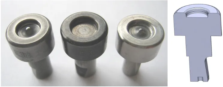
cold-forming process. Fig. 4 shows some typical rivets with a countersunk head and a typical cross-section.
Henrob recently also developed a fully tubular rivet for joining thick stacks to improve bottom
remaining thickness and reduce cracking of bottom less ductile materials [23].
The selection of suitable materials for the rivet manufacturing is restricted by the ability of the
depending on the application. Rivets can also be made from aluminium alloys, copper, brass and
stainless steels, but their applications are very limited because these materials either cannot be
heat-treated to improve their piercing ability or their performance after hardening is poor [7]. In order to
increase the recyclability and reduce the galvanic corrosion potential, aluminium rivets were used for
joining aluminium alloy parts [43-45]. Hoang et al. [43] studied the possibility of replacing a steel
self-piercing rivet with an aluminium rivet when using a conventional die. Their results showed that it
was possible to join 2 mm AA6060 sheet to 2 mm AA6060 sheet in W temper (solution heat treated)
with AA7278-T6 rivets. Reasonable static strengths were achieved as shown in Fig. 5, although the
interlock distances were low, ranging from 0.12 mm to 0.37 mm. Attempts to join higher strength
aluminium alloys or to join AA6060 W with lower strength aluminium rivets were not successful due
to rivet fracture and rivet compression/buckling, respectively. Instead of semitubular rivets, Kaščák and Spišák [29] developed some solid aluminium alloy rivets (no cavity) and used them to join
various steel panels with a good joint geometry and strength. Due to the lower strength and hardness
[image:10.595.111.465.508.728.2]of aluminium rivets, their application will be limited.
FIGURE 5. ―Comparison of the single-joint strength between aluminium rivets and a steel rivet with combined
shearing and pull-out loading with loading angle α = 45o[43].
Self-piercing rivets are normally available with two stem diameters: 3.35 mm (nominal 3 mm) and
5.3 mm (nominal 5 mm). The length of self-piercing rivets available from suppliers ranges from 3.5 to
14 mm. The selection of rivet length is determined by various factors, such as the material stack to be
joined, the die to be used (different geometries and dimensions) and the rivet diameter and hardness.
The rivet length selection guidelines from the European Aluminium Association are as follows: for
rivets of 3 mm diameter, rivet length = stack thickness + 2.5 mm; for rivets of 5 mm diameter, rivet
length = stack thickness + 3.5 mm [46]. Other organizations provided different guidelines. For
example, Henrob, Ltd suggests that the rivet length should be 1.5 – 3 mm and 2 – 4 mm longer than
the stack thickness for 3 mm and 5 mm diameter rivets, respectively. Basically, longer rivets will be
required to join a thicker stack if the materials to be joined and the stack configuration are similar.
Stack configurations can also influence the rivet length selection. Rivets that are shorter than the
recommendation may be used for joining a thin top material to a thick bottom material but not for
joining a thick top material to a thin bottom material.
Steel rivets can be delivered in an as-forged state (softest state) or can be heat-treated to various
hardness levels. The hardness of steel rivets can be about 250Hv (in the as-forged condition) to about
600 Hv. The selection of the rivet hardness is determined by the material stack to be joined. Basically,
a harder rivet should be selected for higher strength and harder materials. If a rivet is too soft for a
material stack, the rivet will buckle or be compressed during the riveting process; on the other hand, if
a rivet is too hard for a material stack, the rivet will exhibit little deformation during the riveting
process, and as a result the interlock distance will not be sufficiently high to hold the bottom material
to provide a high joint strength.
In the early stages of SPR application, the rivet diameter selection was based on the joint stack
thickness, in which thicker stacks would require larger diameter rivets [8]. Nowadays, the influence
factors for selecting the appropriate rivet diameter include the required joint strength, the required
joint robustness, the accessibility to joining area, and the material and stack thickness [47]. Some thin
material stacks can only be joined with 3 mm diameter rivets. Generally speaking, the joints with a 3
mm diameter will have lower strength and robustness for each joint, when compared with those with a
5 mm diameter rivet, and riveting of 3 mm diameter rivets will require smaller access area and flange
size due to a smaller nose piece.
Steel rivets are normally coated to improve corrosion resistance and/or to lubricate the rivet. The
Common coatings include mechanical tin/zinc coatings, mechanical zinc coatings, mechanical Almac
(aluminium and zinc), electric zinc plating, electric tin plating, Kal-gard and epoxy painting for rivet
head etc.
Simulation can be used to design rivets for SPR applications. Xu [48] simulated the influence of
yield strength of the rivet material on the setting process. His results showed that when the yield
strength of a self-piercing rivet material was too low, the rivet deformed before it could pierce the top
sheet, and when the yield strength of the rivet material was too high, the rivet could not be deformed,
such that it could not form an interlock within the sheets. To use the advantage of SPR as a cold
joining process and to make it suitable for joining small structures, Presz and Cacko [49] scaled down
the size of a normal 5 mm diameter self-piercing rivet to a micro-rivet with diameter of 0.7 mm. They
simulated the forming process of 4 different types of micro-rivets, and based on the properties of these
rivets they simulated the micro-SPR joining process. Their results showed that these rivets were
strong enough to obtain micro-SPR joints with a good joint quality.
3.2. Die
Dies used for SPR are usually made of tool steel. They can have different diameters, different
cavity depths and different cavity geometries. Dies can have a cavity with a flat bottom or with a tip
in the middle (pipped die), and they can also have a nearly vertical sidewall or a tilted sidewall. The
geometry of a die will influence the rivet setting force and flaring of the rivet tail. Fig. 6 shows some
[image:12.595.109.481.464.610.2]typical dies and a cross-section.
FIGURE 6. ―Typical dies for SPR and a cross-section.
Die cavity diameters need to be larger than the rivet stem diameters, so that during the riveting
process the rivet tail will have enough space to flare inside the die cavity. Generally speaking, die
diameter does not have much influence on the flare of the rivet legs if it is large enough; however, it
can influence the interlock distance. Dies with larger cavity diameters will produce joints with smaller
cavity diameters have less constraint on the bottom material. So the diameter of the die cavity cannot
be too large. Normally, 3 mm diameter rivets need smaller diameter dies, such as dies with a cavity
diameter of 6 mm or 7 mm, and 5 mm diameter rivets need larger diameter dies, such as dies with a
cavity diameter no less than 8 mm.
Dies for SPR may have a cavity with a flat bottom or a pip in the middle with different geometries
and dimensions. Normally, a pip in the die can enhance rivet deformation and increase the interlock
distance, but it will also introduce larger plastic deformation of the bottom sheet and will require a
larger setting force. So a die with a pip will produce more severe cracks when a less ductile material is
used as the bottom material.
Dies for SPR may have different cavity depth. Normally, a deeper die will provide less support to
the bottom material, and as a result, less force will be required to set the rivet, but a smaller interlock
distance will be generated. In addition, a deeper die will introduce larger plastic deformation in the
bottom sheet and may introduce necking problems at the joint button and cracking issue for less
ductile materials. Consequently, in order to avoid severe cracking, a deep die will not be suitable
when a less ductile material is used as the bottom material.
Research by Li et al. [50] showed that when a less ductile metal is used as the bottom material, it is
better to use dies with a shallow cavity and if possible use dies with a tilted sidewall to avoid
excessive plastic deformation and cracking. They demonstrated that even though the high strength
aluminium alloy AA6008 had good ductility with elongation of more than 20%, when it was joined as
the bottom material using a die with a vertical sidewall and a depth of 2 mm, severe cracks were
generated at the joint button. To reduce the size and number of cracks to an acceptable level, a die
with a more shallow depth and a tilted sidewall was required to join the AA6008 as the bottom
material. Apart from reducing cracking, Sunday [4] also pointed out that a tilted sidewall in a die can
facilitate the die release at the end of riveting.
Proper die design can be used to improve the rivetability of some material stacks. Iguchi and Ohmi
[51] tried to improve the capability of the SPR process. They designed a die that has the capability to
join a thick sheet to a thin and less ductile sheet as the bottom material. By using a spring-loaded
sliding pin in the centre of the die, the excess denting of the top thick sheet could be prevented and the
penetration of rivet into the bottom sheet was increased.
Simulation can also be used to optimise the profile of the die for a particular stack. Mori et al. [52]
conducted simulation using LS-DYNA to optimize the profile of the die to join an ultra-high strength
3.3. Setting force
During the SPR process, a relatively high force, ranging from 20 kN to 100 kN, is required to set a
rivet into a material stack to form a joint through pushing, punching or other methods. The joint will
need to satisfy all the geometry and strength criteria, such as lap shear strength, T-peel strength, rivet
head height, interlock distance and minimum remaining bottom material thickness, so the force cannot
be too high or too low. If the force is too low, the rivet head may protrude out of the top flush surface
that is not good for cosmetics. It may also facilitate corrosion due to the existence of a big gap, into
which water may penetrate. In addition, a low setting-force may lead to a short interlock distance,
which will lead to a joint with low strength. If the force is too high, the indentation caused by the rivet
head may be too large and the minimum remaining bottom material thickness may be too small. A
large indentation may damage the top sheet and reduce the strength of the top sheet to resist the rivet
from being pulled out.
Hill [8] reviewed the parameters that could influence the rivet setting force. The parameters
discussed include the rivet shank diameter, the rivet shank end form (tip geometry), the friction
between rivet and sheet materials, the die shape, the sheet material thickness and hardness, and the
rivet hardness. Hou et al. [36] also studied the parameters that could affect the setting force, including
the die geometry, the rivet length, the material stack, the planar misalignment (gap between the sheet
materials) and the axial misalignment (between the rivet gun and the die). Their results showed that
planar misalignment could change the joint features and reduce the setting force, but slight axial
misalignment did not have obvious influence on the setting force. It is widely agreed that the value of
the setting force depends on the sheet material strength, the material and stack thickness, the rivet
length, the rivet tip geometry, the rivet coating, the rivet hardness and the die geometry etc. Generally
speaking, if other parameters are kept the same, harder/stronger sheet materials, more shallow dies or
dies with a pip, larger rivet diameters, higher friction between rivet and sheet materials, longer or
harder rivets and rivets with blunter tip geometries will require higher setting forces.
3.4. C-frame
The SPR process needs a high setting force typically around 10 times of those used for
spot-welding. Tool alignment for a SPR system also needs to be better than that for spot-spot-welding. As a
result, the C-frame needs to be stronger and more rigid. Information provided by industry suggested
that the deformation of a C-frame during a setting process needed to be restricted within 7 mm along
the loading line with an angular deflection less than 1° [35]. Other parameters that are important for
the C-frame include the throat depth and weight. The throat depth of a C-frame determines the lateral
robot with the C-frame is mounted on and the cost of automation. For easy automation, research has
been undertaken to reduce the weight of the C- frame. Westgate et al. [35] developed a lightweight
deep throat C-frame for an early robot-mounted hydraulic SPR system. Nowadays, electric-servo SPR
systems are preferred, which are much lighter than hydraulic SPR systems and also eliminate the need
for connections to high pressure hoses. As a result, the requirement on the weight of the C-frame is
reduced and the automation of the SPR process becomes easier and less costly.
4. SPR joint quality criteria
In order to produce strong and reliable SPR joints, different users of the technique, including
automotive manufacturers, have set up different joint quality criteria. Among these criteria, there are
three main aspects that need to be controlled, and they are the rivet head height, the interlock distance
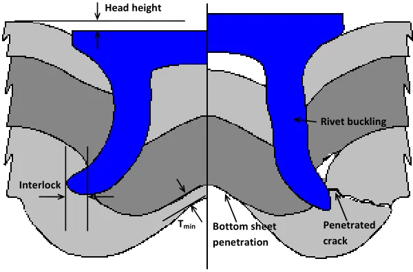
and the minimum remaining bottom material thickness (Tmin), as shown in Fig. 7. The rivet head
height is important for the cosmetic appearance, the tightness of the joints, the gaps between the rivet
head and the top sheet, and the damage of the rivet to the top sheet etc., and consequently the joint
strength. The interlock distance is the most important joint quality, as it will determine the locking
strength between the rivet and the bottom sheet. Although the minimum remaining bottom material
thickness does not have large influence on the joint strength, it is important for noise, vibration and
harshness (NVH) and corrosion. Other joint quality aspects are also considered by different
organizations, such as the cracks at the joint buttons, the buckling of the rivet, the cracks in the rivets,
[image:15.595.134.434.468.666.2]the gaps between the rivet head and the top sheet and the gaps between the sheet materials etc.
FIGURE 7. ―SPR joint quality and some faults.
Head height
Interlock
Tmin Bottom sheet
penetration
Joint quality criteria are substrate material related. For a joint with steel as the bottom
sheet/locking sheet, the minimum required interlock distance can be reduced, because steel is stronger
than aluminium [53]. According to a leading automotive manufacturer, the joint quality criteria
include a rivet head height between 0.3 mm to -0.5 mm (a negative rivet head height implies that the
rivet head is below the flush surface of the top sheet), an interlock distance of at least 0.4 mm for
joints with an aluminium alloy as the bottom sheet and at least 0.2 mm for joints with a steel as the
bottom sheet, and a Tminof at least 0.2 mm (Han et al. 2010a). Generally speaking, the lower the rivet
head height, the higher the interlock distance will be, as reported by Han et al. [54] for mixed
aluminium alloy and steel joints and Li et al. [53] for aluminium alloy joints.
5. Suitable materials for joining using SPR
One of the advantages of SPR is that it can be used to join similar and dissimilar materials. While
SPR is widely applied for joining aluminium structures, it can also be used to join other materials and
mixed materials, including aluminium, steel, magnesium, copper, plastics, wood and composites etc.
Aluminium alloys that can be joined by SPR can be from wrought, extruded and cast alloys. The
grades of wrought aluminium alloys used in automotive body applications include 5xxx and 6xxx etc.
Steels that can be joined by SPR include mild steel, high-strength steels and advanced high-strength
steels.
The general requirements for materials that can be joined by SPR include the following: (i)
materials need to have sufficient ductility, especially for bottom materials that are next to the die, so
severe cracks will not be generated at the joint buttons; (ii) materials need to have a hardness/strength
much less than that of the rivet, so that the rivet can pierce through/into the material and form a
sufficiently high interlock distance without excessive compression or buckling. Brittle materials may
be able to be joined when used as the top or middle material, but not as the bottom material on the die
side without assistance from other sources, such as heating.
For a stack with two layers, the ratio between the thickness of the top and bottom materials can
influence the rivetability of the stack and the strength of the joint. Normally, better rivetability and
strength will be achieved when a thinner sheet is used as the top material and a thicker sheet is used as
the bottom material. However, due to access limitations and other issues, sometimes rivets can only
be pierced from the thicker sheet side, and in this case careful design/selection of rivets and dies is
required to achieve the desired joint quality.
The study of the rivetability of various material combinations has been the subject of several
investigations. Abe et al. [15] studied the joinability of an aluminium alloy to mild steel, and their
top sheet needed to be thinner than the bottom sheet. They also demonstrated that to join the steel as
the top sheet and the aluminium alloy as the bottom sheet, a better joinability can be achieved than to
join the aluminium alloy as the top sheet and the steel as the bottom sheet. Mori et al. [52] studied the
feasibility of joining an ultra-high strength steel to an aluminium alloy using SPR. They found that if
the rivet was not hard enough, joint defects from rivets could occur, such as the rivet fracture, the rivet
compression and the rivet bending, as shown in Fig. 8. These rivet defects will normally occur when
the rivet is too soft for the materials to be joined. With the optimized rivets and dies, they then
successfully joined the SPFC980 ultra-high strength steel (tensile strength around 980 MPa) to
AA5052-H34. Another example of rivet failure by compression and fracture during the riveting
[image:17.595.86.509.261.395.2]process was shown by Hoang et al. [43], when they joined aluminium alloys with aluminium rivets.
FIGURE 8. ―Possible joint defects for joining an ultra-high strength steel to an aluminium alloy by SPR [52].
The joining of magnesium alloys using SPR has been studied by various researchers. Magnesium
alloys have low ductility at room temperature due to their hexagonal lattice structure, but their
ductility increases with the increase of temperature. Research by Hahn and Horstmann [55] showed
that after locally heating magnesium alloy AZ31 to 280oC using induction heating, it was possible to
join AZ31 as the top and/or bottom materials by SPR and clinching. Durandet et al. [56] proposed to
use laser assisted SPR to join magnesium alloys. When wrought strips of AZ31B-H24 magnesium
alloy with a thickness of 2.35 mm and 3.2 mm were heated above 200oC, the AZ31 could be
successfully self-piercing riveted without cracks.
Sjöström [57] studied the possibility of self-piercing riveting a cast magnesium alloy (AM60B) to
an ultra-high strength steel (Dogal DP800). They found that the ductility of the magnesium alloy
limited the use of SPR; severe cracking of the magnesium alloy sheet occurred in all tested
configurations, but the number of cracks could be reduced by local heating of the magnesium alloy
substrate. Local heating of the magnesium alloy substrate not only suppressed the cracking of the
magnesium alloy when it was used as the bottom sheet, but also improved the setting of the rivet head
and promoted the interlocking. To achieve sufficient interlocking between the rivet and the sheet
materials and obtain an optimal joint strength, the thicker magnesium alloy substrate needed to be
[image:18.595.72.538.144.455.2]placed on the die-side.
Table 1. ―Typical mechanical properties of the aluminium and magnesium alloys [58].
Alloy Yield Strength, Mpa Tensile strength, Mpa Elongation, %
Extruded AA6063-T6 215 240 12
Die cast AM50 125 210 10
Sheet AA5754-O 100 220 26
Sheet AZ31B-O 150 255 21
FIGURE 9. ―The cross-section of a SPR joint with extruded AA6063 and die-cast magnesium alloy AM50
[58].
Luo et al. [58] studied the rivetability of magnesium alloys to aluminium alloys. Table 1 shows the
mechanical properties of the alloys that were used. The results showed that when used as the top
material, the die-cast magnesium alloy AM50 could be self-piercing riveted to the extruded AA6063,
but when the AM50 was joined as the bottom material, severe cracks occurred at the joint buttons, as
shown in Fig. 9. However, it was possible to join the extruded AA6063 as the bottom material due to
its better ductility. Because AA5754 and wrought magnesium alloy AZ31 had large elongations, 26%
and 21%, respectively, it was possible to join both AA5754 and AZ31 as the top and bottom
materials.
Apart from the influence of local heating on the rivetability of magnesium alloys, Wang et al. [59]
also studied the influence of local heating on the joint strength and the failure modes. They found that
when riveting 2 mm AZ31 to 2 mm AZ31 at room temperature, severe cracking occurred at the joint
observed that by pre-heating the AZ31, the lap shear strength of the joints could be increased and the
failure of joints during lap shear tests changed from tearing of the bottom sheet to rivet being pulled
out from the bottom sheet. SPR can also be used in combination with adhesive to join magnesium
alloys to achieve a higher joint strength [60].
The variation in the results presented by different researchers on the rivetability of magnesium
alloy AZ31 may be caused by the different mechanical properties of the alloy. AZ31 can be produced
through different processes, such as die-casting, extrusion and rolling, resulting in different ductility.
Copper sheets have excellent ductility. SPR has been successfully used to join aluminium to
copper [61] and copper to copper [62].
SPR has also been tried to join sandwich materials. Pickin et al. [63] demonstrated that it was
possible to join a sandwich material (0.2 mm steel+1.6 mm polymer+0.2 mm steel) to a 2 mm thick
aluminium alloy using SPR. Unpublished results from the University of Warwick also showed that it
[image:19.595.146.440.374.521.2]was possible to join steel/polymer sandwich materials to achieve a high joint strength.
FIGURE 10. ―The cross-section of a SPR joint with 2 mm glass fibre composite and 2 mm AA6082 T6
(modified from [64])
In addition, the feasibility of using SPR to join composites to aluminium alloys has been
investigated. Fratini and Ruisi [64] studied the feasibility of a joining glass-fibre composite to an
aluminium alloy, and they found that it was possible to join them by SPR. However, due to the brittle
nature, the glass-fibre composite could only be used as the top material, as shown in Fig. 10. Research
by Di Franco et al. [65] showed that SPR could be used to join a carbon fibre reinforced polymer
(CFRP) composite to aluminium alloys with reasonable joint strength. Settineri et al. [66] studied the
joining of polymer and polymer based composites to aluminium alloys. Their results demonstrated
composites to aluminium alloys by SPR and by a combination of SPR and adhesive. Di Franco et al.
[67] demonstrated that by combining SPR and adhesive bonding, a high strength, a high stiffness and
high energy absorption could be achieved. Fiore et al. [68] studied the mechanical performance of a
Basalt Fiber Reinforced Polymer to aluminum alloy AA6086 mixed joints. Their results showed that
the strength of the self-piercing riveted joints was lower than that of the adhesive bonded joints.
The SPR process for joining composites to aluminium alloys was also studied through experiments
and simulation. Di Franco et al. [69] studied the SPR process for joining a CFRP to an aluminium
alloy through experiments and finite element modelling. Later, they reviewed their research with
additional emphasis on understanding the failure mechanisms [65, 70]. Results showed that applied
oil pressure of the electro-hydraulic riveting system had significant influence on the joint strength.
They found that the SPR process could be simulated using the finite element code DEFORMTM2D,
and the predicted joint features and force–displacement curve matched well with the experimental
results. Mechanical tests showed that during static lap shear tests, all specimens failed by rivet being
pulled out from the top CFRP panel, and during a lap shear fatigue test, specimens failed at the top
CFRP panel around the rivet head or at the bottom aluminium alloy sheet along the joint button.
SPR can be used to join composites, as top or middle material, to metal materials. However, it is
clear that the SPR process can damage the reinforcing fibres and cause delamination during the
riveting process, which will reduce the strength of the composite. The standard SPR process is
believed not suitable for joining composites to composites because of the brittle nature of composites
and delamination. Researchers are trying to solve the issues faced by SPR when joining plastics and
composites. Henrob Ltd. [71] developed a new SPR process using a predrilled washer between the
rivet head and the top sheet and a non-drilled washer below the bottom sheet; in this process, the rivet
pierces through both the top and bottom sheets and flares into the lower washer. This process was
used to join Lotus Elan’s glass-fibre reinforced plastics (GRP) floor pan. Ueda et al. [72] introduced a
modified SPR process, in which two predrilled washers were introduced, with one between the rivet
head and the top of the stack and the other between the bottom of the stack and the bended rivet skirt.
By setting the rivets this way, the delamination of the composites was sufficiently suppressed;
however, there might be issues for aligning the rivet with the washers and the additional weight and
cost of the washers.
6. Mechanical performance of SPR joints
6.1. Contributing elements of static strength
Knowing the contributing elements of the static strengths of a SPR joint is very important for
joint should be a combination of a direct shear force and a frictional force at the sheet interface.
However, he also suggested that the strength of a SPR joint was difficult to predict, because the
compression force in SPR joints, essential for friction, was not high and would be unpredictable.
A number of other researchers have also suggested that the frictional forces between the sheet
materials and between the rivet and the sheet materials are very important in the determination of the
static strength of SPR joints. Han and Chrysanthou [73] demonstrated that the residual compression
pressure from the rivet setting process could influence the frictional force between the rivet and the
sheet material, and consequently the static strength. Results from Han et al. [73, 74] also showed that
sheets with different surface conditions would require different rivet setting forces and result in
different joint strength and failure modes due to different friction behaviour at the interfaces. Later, Li
et al. [75, 76] pointed out that the friction between the top and bottom sheets, around the tip of the
punched hole in the top sheet, was very important for the static lap shear strength.
In the case of SPR with two layer of materials, it is believed that the strength of a SPR joint is a
combination of (i) the force to deform the top material underneath the rivet head or the bottom
material locked by the rivet tail, (ii) the frictional force between the rivet head and the top sheet or
between the rivet tail and the locked bottom sheet, and (iii) the frictional force between the top and
bottom sheets, especially around the tip of the punched hole in the top sheet. However, the influence
of the frictional force between the top and bottom sheets on T-peel and cross-tension strength is not
significant.
6.2. Influence of rivets, dies, sheet materials and stack orientations
Han et al. [77] demonstrated that the strength of SPR joints was affected by the selection of rivets,
dies and sheet materials due to the different joint features and materials strength. Hill [8] studied the
static lap shear and cross-tension strengths of the SPR joints for steel and an aluminium alloy and
presented some typical strength of single-rivet joints with various stack thickness.
The influence of the sheet materials on joint strength can be from the sheet thickness, the stack
thickness and the material strength. Madasamy et al. [78] studied the static and impact behaviours of
some aluminium alloy SPR joints, where the sheet thickness was 1 mm, 2 mm and 3 mm. They found
that the joint strength was sensitive on the thickness of the top sheet. Further studies from Madasamy
et al. [79] investigated the crash performance of the aluminium alloy and steel rails joined by SPR. It
was found that for the aluminium alloy crash rails, the thickness of the sheet material was the main
factor that influenced the performance, and for the steel crash rails, the sheet material thickness, the
Research by Hill [8] showed that for both the steel and aluminium alloy SPR joints, the lap shear
and cross-tension strength increased with the increase of the stack thickness, and research by Taylor
[80] showed similar results. Porcaro et al. [81] also demonstrated that the strength of the SPR joints of
aluminium extrusion AA6060 increased with the increase of the stack and sheet material thickness
and the material strength, as shown in Fig. 11, but the joint strength was not influenced by the width
of the plate.
FIGURE11. ―Representative experimental lap shear force-displacement curves for the U-shaped specimens
with different material strength, sheet thickness and stack thickness (modified from [81]).
Li and Fatemi [82] studied the mechanical performance of the aluminium alloy SPR joints in
T-peel/coach peel configuration. Their results showed that the static T-peel strength of the SPR joints
normally increased with the increase of the stack thickness, excepting that the 3 mm+3 mm (first sheet
as the top sheet and the second sheet as the bottom sheet) SPR joints had poorer static T-peel strength
than the 2 mm+3 mm and 2 mm+2 mm specimens. Li and Fatemi pointed out that sheet thickness was
not the only factor that influenced T peel strength, and they believed that the higher stiffness against
plate bending for the 3 mm+3 mm specimens and the subsequent lower friction and higher shear
forces between the contact surfaces were the reason that caused the lower strength of that stack. Li
and Fatemi neither disclosed the details of the rivets used for the different material stacks, nor
presented the joint features, such as the interlock distance and the rivet head height. It is possible that
the rivet used for the 3 mm+3 mm SPR specimens did not generate a sufficiently high interlock
distance or the rivet head had deeper penetration in the top sheet, leaving the joint less resistant to the
rivet being pulled out.
Khanna et al. [83] studied the mechanical properties of self-piercing riveted AA6111 aluminium
alloy joints of various thickness combinations. Their results showed that for joints with equal
thickness for the top and bottom sheets, the static and fatigue strength (lap shear and T-peel) both
increased with the increase of sheet material thickness. For joints with unequal top and bottom sheet
thickness, the strength of the joints was greatly determined by the thinner sheet.
Li et al. [50] evaluated the joint quality and the mechanical strength of a high strength aluminium
alloy SPR joints. The results showed that the static lap shear and T-peel strength of the joints
increased greatly with the increase of the top material (AA5754) thickness, but the increase of bottom
material (AA6008) strength, from 195 MPa to 250 MPa, only had marginal influence on the static
joint strength. It was also demonstrated that when the AA6008 sheet was joined as the bottom
material, a thinner top material could make the cracking of the bottom AA6008 more severe than a
thicker top material.
FIGUREF 12. ―Influence of the amount of pre-straining on the static and fatigue lap shear strength of the
single rivet SPR joints [84].
(a)
Many parts used in automotive body structures are stamped, and during the stamping process
materials are strained. In order to determine the influence of stamping, Han et al. [84] studied the
influence of pre-straining on the mechanical behaviour of aluminium alloy joints. The stack they
studied had 2 mm AA5754 as both the top and bottom sheets, and they compared the static and
fatigue lap shear strength of the specimens with the original AA5754 and the AA5754 with 3%, 5%
and 10% pre-strain. They found that the pre-straining improved both the static and fatigue strength of
the joints, as shown in Fig. 12.
SPR joints with different rivets may have different joint strength due to the different rivet
diameters, rivet hardness, and rivet lengths. The influence of the rivet tip geometry on joint strength
will be discussed separately in a later section. Results from Hill [8] and Taylor [80] showed that for
both steel and aluminium alloy SPR joints, the joints with larger diameter rivets exhibited higher
shear and tension strength. Madasamy et al. [78] demonstrated that the joints with 5 mm diameter
rivets had higher strength and higher energy absorption than the joints with 3 mm diameter rivets.
These observations are probably due to the increased strength of rivet itself, the increase interlock
distance and the increased rivet head size. Influence of the rivet length on joint strength is mainly
caused by different joint features, such as the rivet head height, the interlock distance and the
minimum remaining bottom material thickness (Tmin). SPR joints with longer rivets normally have
higher joint strength and energy absorption due to a larger interlock distance, providing that the rivet
head height and Tminare similar.
The influence of the stack orientation (rivet setting direction) on joint strength is mainly due to the
resulting different joint features and for mixed material stacks, the strength difference of the top and
bottom materials. Madasamy et al. [78] studied the influence of stack orientation on the joint strength
of aluminium stacks. An aluminium alloy with different thickness of 1 mm, 2 mm and 3 mm was
used, and their results showed that with the same stack thickness, setting the rivet through the thinner
sheet side would result in the joint having higher strength and energy absorption. Similarly, Porcaro et
al. [81] presented that the use of a thicker material as the bottom sheet would normally produce the
joints with higher strength than the use of a thinner material as the bottom sheet. Sun [85] and
Stephens [86] studied the influence of stack orientation on the joint strength of mixed aluminium and
steel stacks. Fig. 13 shows the cross-sections of two stacks with reversed orientations. Their results
showed that the stack of joining 1 mm HSLA 350 to 2 mm AA5182 O had better strength and energy
absorption than the reversed stack with 1 mm HSLA 350 as the bottom materials in lap shear, T-peel
and cross-tension, as shown in Fig. 14. However, they also showed that for a different pair of stacks
with DP600 and AA5182 O, the stack with DP600 as the bottom materials had lower lap shear
strength but higher T-peel and cross-tension strength. Generally speaking, stack orientation will
strength, loading directions and failure modes. However, it is believed that joining a stack with a
thinner material as the top material will be easier and have larger process window, since it is easier to
achieve enough interlock without over-thinning or penetrating the bottom material.
FIGURE13.―The cross-sections of SPR joints with different stack orientations but the same rivet and die, a) 2 mm AA5182 O+1 mm HSLA 350, and b) 1 mm HSLA 350+2 mm AA5182 O (modified from [85]).
14.―
a
In order to further reduce vehicle weight, new lightweight or high strength materials need to be
introduced into the structure, but some of them have higher tendency to crack when they are joined by
SPR. Li et al. [87] studied the influence of the die profile and the joint button cracks on the
mechanical performance of the self-piercing riveted high strength aluminium alloy joints. The results
showed that due to the large bending and tension deformation, the dies with a deep cavity and/or
sharp corners would tend to cause severe cracks for some materials (such as the high strength
aluminium alloy AA6008T61), when they were joined as the bottom material, as shown in Fig. 15.
They also found that a thinner material had a lower tendency to crack than a thicker material due to a
lower bending stress. Their study suggested that cracks on joint buttons could reduce the static and
[image:26.595.130.445.280.537.2]fatigue lap shear strength but had no obvious influence on the static and fatigue T-peel strength.
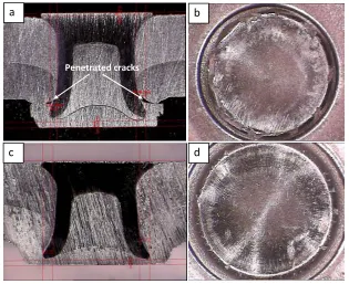
FIGURE 15. ―The cross-sections and button images of the SPR joints (3.0AA5754+2.5AA6008 T61 215 MPa)
with, a) b) the deep and sharp corner die and c) d) the shallow and tilted sidewall die (modified from [87]).
One of the joint defects that may occur is the bottom sheet breakthrough (rivet penetrates the
bottom sheet), which may be caused by an overlong rivet, an over high setting force or a wrong die
used. Han et al. [88] studied the effect of the bottom sheet breakthrough on the mechanical behaviour
of the self-piercing riveted aluminium AA5754/HSLA (high strength low alloy steel) joints. 2 mm
thick AA5754 aluminium alloy and 1 mm thick HSLA were used in the study. Their results showed
that the breakthrough in the bottom sheet had a minor effect on the shear strength of the joints, but
there was a significant effect on the peel strength. The breakthrough led to the change of failure
modes for the lap shear tests. During the lap shear tests, the joints with breakthrough failed by tearing
Penetrated cracks
a
d c
of the bottom sheet, and the joints without breakthrough failed by the rivet being pulled out from the
bottom sheet; during T-peel tests, all specimens failed by the rivet being pulled out from the bottom
sheet. The joints with breakthrough had larger interlock distances that determined the rivet pull-out
strength from the bottom sheet, but reduced the strength of bottom sheet against tearing. As a result,
the joints with breakthrough had slightly lower lap shear strength, but much higher T-peel strength.
Their results also showed that the breakthrough slightly affected the fatigue life and accelerated the
corrosion behaviour of the self-piercing riveted joints, because the breakthrough facilitated the
penetration of corrosion media through the broken bottom sheet.
In order to increase the SPR joint strength of a thicker aluminium joined to a thinner steel, Lou et
al. [34] used resistance spot-welding after SPR. Their results showed that by doing this a 12% lap
shear strength increase could be achieved.
Based on the reported research, the actual strength of a SPR joint will depend on the stack
orientations (rivet setting direction), the material and stack thickness, the top and bottom material
thickness ratio, the combination of rivet and die used, and the rivet setting force etc. Generally
speaking, joints with larger diameter rivets normally have larger strength than those with smaller
diameter rivets, since rivets with a larger diameter will have larger contact areas with the sheet
materials, which will make the deformation of the sheet materials more difficult and the frictional
force between the rivet and the sheet material larger. Rivets with a larger diameter are also more
difficult to be deformed. When a different rivet and die are used to produce a joint, the joint will have
different joint features, such as interlock distance, rivet head height and Tmin, and as a result the joint
will have different strength. Typically, SPR joint strength increases with the increase of the sheet
material thickness or the stack thickness. For joints with unequal top and bottom sheet thickness, the
strength of the joints will be greatly determined by the thinner sheet and the joint strength will
normally be higher if the thick material is used as the bottom material. When materials with different
strength are used, for a similar stack configuration, the joints with higher strength materials will
normally have higher strength, and similarly pre-straining of materials can also increase the joint
strength.
6.3. Influence of setting force
In order to satisfy the joint quality criteria, for a specific combination of a material stack, a rivet
and a die, only certain range of setting force can be used. Different setting forces will produce joints
with different joint qualities, and as a result with different mechanical performances. Researches have
been conducted to investigate the influence of setting force on the mechanical performances of SPR
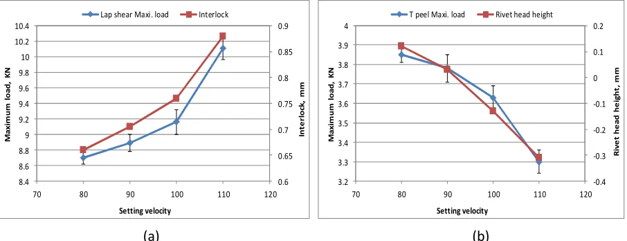
Li et al. [53] studied the influence of the setting velocity/force on the performance of 2 mm
AA5754+2 mm AA5754 SPR joints. The results showed that an over-high velocity would leave a big
dent on the top sheet and an over-low velocity would leave the rivet head protruding out of the top
sheet. In their research, all the lap shear specimens failed by the rivet being pulled out from the
bottom sheet and all the T-peel specimens failed by the rivet being pulled out from the top sheet.
From these observations, they proposed that for the stack studied, the static lap shear strength was
determined by the interlock, while the static T-peel strength was determined by the rivet head height.
Their results showed that as the setting velocity increased, the interlock distance of the joints
increased, but the rivet would penetrate more into the top sheet with a lower head height, which would
damage the top sheet and reduce its resistance against the rivet being pulled out from the top sheet. As
a result with the increase of setting velocity within the range studied, the lap shear strength of the
joints increased, but the T-peel strength of the joints decreased, as shown in Fig. 16. They also studied
the fatigue performance of the joints and found that the setting velocity did not have a significant
influence on the lap shear fatigue strength, because all specimens failed at substrate materials next to
the joints, not at the joints themselves. However, for T -peel fatigue at low loads, the fatigue strength
of the joints increased with the increase of setting velocity until it reached certain value. This was
attributed to the retarding of bending crack initiation at low fatigue loads from the residual
compression stress generated during the riveting process, which was higher at a higher setting
[image:28.595.71.524.437.611.2]velocity/force.
FIGURE 16. ―The strength and joint features of the joints produced with different setting velocities, a, lap
shear strength and interlock, b, T-peel strength and rivet head height [53].
Similarly, Han et al. [54] studied the influence of the setting velocity/force on the joint quality and
the mechanical behaviour of aluminium alloy/steel mixed joints. Their results showed that the setting
velocity affected the SPR joint quality: as the setting velocity increased, the head height and
remaining material thickness decreased, but the interlock distance increased. Their results also
(b) (a) -0.4 -0.3 -0.2 -0.1 0 0.1 0.2 3.2 3.3 3.4 3.5 3.6 3.7 3.8 3.9 4
70 80 90 100 110 120
R iv e t h e ad h e ig h t, m m M ax im u m lo ad , KN Setting velocity
T peel Maxi. load Rivet head height
0.6 0.65 0.7 0.75 0.8 0.85 0.9 8.4 8.6 8.8 9 9.2 9.4 9.6 9.8 10 10.2 10.4
70 80 90 100 110 120
In te rl o ck , m m M ax im u m lo ad , KN Setting velocity
showed that a higher setting velocity would lead to a higher lap shear joint strength but a lower T-peel
strength.
An earlier investigation by Fu and Mallick [89] showed that the joints produced using a higher
rivet setting pressure had a higher static lap shear strength, but the rivet setting pressure did not have
an obvious influence on the fatigue strength. When the rivet setting pressure was over 95 bar, the
influence of setting pressure on the lap shear strength became insignificant. Considering that the rivet
setting pressure is a process parameter that controls the rivet setting force, Fu and Mallick’s results are
consistent with those reported by Li et al. [53].
6.4. Comparison of SPR joints with joints from other processes
Resistance spot-welding has been widely used in the automotive industry for steel body-in-white
structures for decades, but when it came to the joining of aluminium alloys, pre-finished materials and
dissimilar materials, spot-welding became less attractive and has been replaced by SPR. Since spot
welding is an established welding process for automotive structures, a large amount of research has
been conducted to compare the performance of the SPR joints with that of the spot welded joints.
Most of the comparisons were conducted for aluminium alloy joints due to the increased
application of aluminium alloys in the automotive body structures. Sunday [4] compared the
mechanical strength of various SPR and resistance spot-welded (RSW) aluminium alloy joints. In his
study, steel rivets with a stem diameter of 4.76 mm were used for SPR, while the joint nugget
diameter of the spot-welded joints ranged from 4.67-5.67 times of the square root of the thinner sheet
material thickness. The results showed that the SPR joints could have higher or lower lap shear
strength than the spot-welded joints for different material stacks, and the SPR joints had lower tension
strength than the spot-welded joints. Even though the SPR joints for the 2.16 mm AA5182+2.16 mm
AA5182 stack had a lower static lap shear strength than the spot-welded equivalent joints, the SPR
joints had superior fatigue strength. This fatigue behaviour was in agreement with the results
presented by Partrick and Sharp [5]. Similar results were also reported by Khanna et al. [83] for
AA6111 joints and Blacket [90] for AlMg3W19 joints. Riches et al. [91] compared the static peel and
shear strength of the SPR riveted, spot-welded and clinched 1.6 mm AA5182+1.6 mm AA5182 joints.
They found that the strength of the spot-welded joints were higher than that of the clinched joints but
lower than that of the SPR joints. Doo [7] compared the static joint strength of the SPR and
spot-welded 5000 series aluminium alloy joints with different joint thickness. He found that the SPR joints
had a better lap shear strength, when the joint thickness was 2 mm and 3.2 mm, but a lower lap shear
strength when the joint thickness was 4.3 mm; the SPR joints had a better peel strength than the
fastened aluminium alloy joints. The material stack they studied was 2 mm AA5754+2 mm AA5754.
They used 6 mm diameter rivets but did not disclose other details of the rivets. From their results, the
static lap shear strength of the SPR joints with the steel rivets was much lower than that of the
spot-welded joints. However, the SPR joints had superior lap shear fatigue strength. Results from
Mizukoshi and Okada [93] also showed that the SPR aluminium joints with a lower static lap shear
[image:30.595.110.471.182.396.2] [image:30.595.118.464.439.654.2]strength had a better fatigue performance than the spot-welded aluminium joints.
FIGURE 17. ―Comparison of the static shear strength of SPR and spot welded aluminium alloy joints
(Regenerated from [7]).
FIGURE 18. ―Comparison of the static peel strength of SPR and spot welded aluminium alloy joints
(Regenerated from Doo [7]).
Briskham et al. [94] compared the static strength of various SPR joints with that of resistance
spot-welded (RSW) joints and spot-friction-spot-welded joints. Their results showed that the SPR joints had 0 1 2 3 4 5 6 7
2 3.2 4.3
Jo in t Fa ilu re Lo ad (k N )
Joint Thickness (mm)
SPR Spot Weld
0 0.5 1 1.5 2 2.5
2 3.2 4.3
Jo in t Fa ilu re Lo ad (k N )
Joint Thickness (mm)

![FIGURE 8. ―Possible joint defects for joining an ultra-high strength steel to an aluminium alloy by SPR [52].](https://thumb-us.123doks.com/thumbv2/123dok_us/9487464.454914/17.595.86.509.261.395/figure-possible-joint-defects-joining-ultra-strength-aluminium.webp)
![Table 1. ―Typical mechanical properties of the aluminium and magnesium alloys [58].](https://thumb-us.123doks.com/thumbv2/123dok_us/9487464.454914/18.595.72.538.144.455/table-typical-mechanical-properties-aluminium-magnesium-alloys.webp)
![FIGURE 10. ―The cross-section of a SPR joint with 2 mm glass fibre composite and 2 mm AA6082 T6(modified from [64])](https://thumb-us.123doks.com/thumbv2/123dok_us/9487464.454914/19.595.146.440.374.521/figure-cross-section-joint-glass-fibre-composite-modified.webp)
![FIGURE 17. ―Comparison of the static shear strength of SPR and spot welded aluminium alloy joints(Regenerated from [7]).](https://thumb-us.123doks.com/thumbv2/123dok_us/9487464.454914/30.595.118.464.439.654/figure-comparison-static-strength-welded-aluminium-joints-regenerated.webp)