Abstract— In this paper, an analytical solution in closed form is developed to determine stresses (radial and circumferential) made of functionally graded materials subjected to variable thickness and pressure. In this, Poisson ratio is taken as constant and the Young’s modulus depends on the radial coordinate only. For higher pressure a significant increase is seen for both radial and tangential stresses. Graphs are drawn for stresses and displacement against radii ratio and numerically discussed.
Index Terms— Rotating disc, Variable thickness, Pressure,
FGM.
I. INTRODUCTION
UNCTIONALLY graded materials (FGM) are from the class of advanced material, categorized by the changes in the properties with the changes in the dimensions of the material. The properties of FGM are different from the properties of the constituent materials. In fact, the constituent materials forming FGM have less ductility and strength. Dynamic properties of functionally graded materials lead to the widespread range of its applications in various fields. Due to the unique graded material properties, FGMs have attracted a great amount of attention from researchers in many fields, including aerospace, biomaterials and engineering among others in the past decades. It differs from composite materials, which fails under extreme working conditions through a process called delamination (separation of fibers from matrix). FGM removes the sharp interfaces existing in composite materials where the failure occurs. It replaces the sharp interface with a gradient interface which produces smooth transition from one material to another.
These materials are characterized by a microstructure that is spatially variable on a macroscale and were initially developed for high temperature applications [1-2]. A review on FGMs and its applications can be found in some of the
Manuscript received September 04, 2015; revised October 15, 2015. Tajinder Pal Singh is with the Department of Mathematics and Computer Science, School of Technology, Pandit Deendayal Petroleum University, Gandhinagar, Gujarat-382007, INDIA. (e-mail: [email protected]).
Manoj Sahni is with the Department of Mathematics and Computer Science, School of Technology, Pandit Deendayal Petroleum University, Gandhinagar, Gujarat-382007, INDIA. (corresponding author phone: +9179-2327-5470; fax: +9179-2327-5030; e-mail: [email protected]).
research papers [3-4]. You et al. [5] calculated stresses on the functionally graded rotating circular discs under uniform temperature and variation in Young’s modulus. An analytical solution for stresses is developed for a thin annular disk made of FGM under pressure by You et al. [6]. A numerical approach using FEM model is used for solving problem of a rotating thermo elastic circular disk made of FGM material by Sharma et al. [7] in 2012. Effect of thermal gradient in a secondary creep region of a rotating disc with variable thickness is studied by Garg et al. [8]. Sahni et al. [9] solved problem of a circular annular disc under pressure using stress function for an axis-symmetric case with variable thickness profile. Strength analysis of functionally graded disc brake subjected to mechanical loading is done by Rajeshwari et al. [10]
In this paper, we study the strength analysis of FGM under variation in variable thickness and Young’s modulus considering both internal and external pressure. A closed-form analytical solution is obtained and the results are discussed numerically and depicted graphically. The graphs are drawn using MATHEMATICA 5.2 software. For obtaining the results the gradient parameter are chosen between 0 and 1.0. Results obtained are compared with the research paper by Callioglu [11].
II. GOVERNING EQUATIONS
Consider an annular disk of internal and external radii ‘a’ and ‘b’ respectively, subjected to internal and external pressure
and
respectively and variable thickness ‘h’ rotating with an angular speedω
.Equations of equilibrium are all satisfied except,
{
}
2 2( )
rr( )
( )
0,
d
h r rT
h r T
h r
r
dr
−
θθ+
ρω
=
(1)
where
h r
( )
is the thickness of the disc varying with position vector ‘r’ and densityρ
is constant. Hereܶ
andܶ
ఏఏ are the radial and tangential stresses respectively.The problem of plane stress is considered for functionally graded materials with the variation in Young’s modulus and thickness in a form, given as
ܧሺݎሻ = ܧݎ
,
ℎሺݎሻ = ℎݎ(2)
Study of Strength of Rotating Discs of
Innovative Composite Material
with Variable Thickness
Tajinder Pal Singh and Manoj Sahni
Here
E
0 andh
0 are Young’s modulus and thickness at m = 0 and n = 0 respectively. The parameter ‘m’ and ‘n’ in equation (2) are geometric parameters.The strain displacement relationship are given by
dr
du
r
=
ε
andu
,
r
θ
ε
=
(3)
where
ε
r andε
θ are strains along radial andcircumferential direction respectively. Here u is the displacement in the radial direction.
The strain compatibility equation is
(
)
.
rd
d
r
r
dr
dr
θ θ θε
ε
=
ε
=
ε
+
(4)
The stress - strain relationship is defined as
)
(
)
(
1
θθυ
ε
T
T
r
E
rrr
=
−
and1
(
).
( )
T
T
rrE r
θ θθ
ε
=
−
υ
(5) The factor ν is the Poisson’s ratio, which is constant. Defining the stress function (F) satisfying the equilibrium equation of motion (1) as
( )
rrF
T
r h r
=
and'( )
2 2( )
F r
T
r
h r
θθ
=
+
ρω
(6)
Now using equations (2), (5) and (6) into a compatibility equation (4), we get
ݎଶܨ′′+ ݎܨ′ሺ1 − ݉ − ݊ሻ + ܨሺߥሺ݉ + ݊ሻ − 1ሻ =
−ߩℎ߱ଶݎାଷሺ3 + ߥ − ݉ሻ (7)
The stress function F is calculated as
ܨ = ܥଵݎఒభ+ ܥଶݎఒమ−ߩℎ߱
ଶሺ3 + ߥ − ݉ሻݎାଷ ܣ
(8)
where ܥଵ and ܥଶ are the constants, and ܣ = 8 + 3݊ − 3݉ − ݉݊ + ߥሺ݉ + ݊ሻ.
Here
ߣ
ଵ=
ାାඥሺାሻమିସሺఔሺାሻିଵሻ
ଶ and
ߣ
ଶ=
ାିඥሺାሻమଶିସሺఔሺାሻିଵሻ .Using (8) in (6), radial and circumferential stresses are calculated as
ܶ
=
భబݎ
ఒభିିଵ+
మబݎ
ఒమିିଵ−
ఘఠమሺଷାఔିሻ
ݎ
ଶ(9)
ܶ
ఏఏ=
ఒభభబ
ݎ
ఒభିିଵ
+
ఒమమబ
ݎ
ఒమିିଵ
−
ఘఠమሺଷାఔିሻሺାଷሻ
ݎ
ଶ.
(10)
The boundary conditions are defined as
ܶ= −
at
r
=
a
ܶ = −
at
r
=
b
.
(11)Using boundary conditions (11) in equation (9), we get the integration constants ܥଵ and ܥଶ as
C1 = h
∗
ۉ ۈ ۈ ۇp୧∗ ܾ
ଶି୬ିଵ− p
∗ ܽଶି୬ିଵ− ߩ ∗ ߱
ଶ∗ ሺ3 + ߥ − mሻ
A ∗
ሺܽଶ∗ ܾଶି୬ିଵ− ܾଶ∗ ܽଶି୬ିଵሻ ܾଵି୬ିଵ∗ ܽଶି୬ିଵ− ܾଶି୬ିଵ∗ ܽଵି୬ିଵ
ی ۋ ۋ ۊ (12) C2
= h
∗
ۉ ۈ ۈ ۇp୧∗ ܾ
ଵି୬ିଵ− p
∗ ܽଵି୬ିଵ− ߩ ∗ ߱
ଶ∗ ሺ3 + ߥ − mሻ
A ∗
ሺܽଶ∗ ܾଵି୬ିଵ− ܾଶ∗ ܽଵି୬ିଵሻ ܾଶି୬ିଵ∗ ܽଵି୬ିଵ− ܾଵି୬ିଵ∗ ܽଶି୬ିଵ
ی ۋ ۋ ۊ . (13) Radial displacement (u) is calculated from equation (3) and (5) as
(
)
( )
rrr
u
T
T
E r
θθν
=
−
(14)
III. NUMERICAL DISCUSSIONS WITH GRAPHS In this paper, stresses – radial and circumferential, displacement are calculated by varying geometric parameter ‘m’ and ‘n’. The values that are being taken are listed below: a = 50 mm., b = 100 mm., ω = 650 rad/s, m, n = 0, 0.5, 0.9, p = 20, 30 Pa, ρ =5600 kg/ m3.
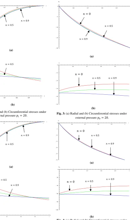
In figures 1 to 4 radial and circumferential stresses against radii variation has been plotted under internal and external pressure keeping the effect of rotation. It is seen from figure 1 that with the increase in geometric parameters ‘m’ and ‘n’ the circumferential stress decreases. The radial and circumferential stresses both increases with the increase in internal pressure which can be observed from figures 1 and 2. The radial stress is always less than the hoop stress which resists the disk to move out and cause the disk to fail. The maximum stress is at the internal radii because of the internal pressure. An inverse behavior is seen when the disk is subjected to external pressure. Because of the external pressure, the stresses are maximum at the external radii.
(a)
(b)
Fig. 1: (a) Radial and (b) Circumferential stresses under internal pressure = 20.
(a)
(b)
Fig. 2: (a) Radial and (b) Circumferential stresses under internal pressure = 30.
(a)
(b)
Fig. 3: (a) Radial and (b) Circumferential stresses under external pressure = 20.
(a)
(b)
Fig. 4: (a) Radial and (b) Circumferential stresses under external pressure = 30.
0.6 0.7 0.8 0.9 1
r
-20 -15 -10 -5 sr
0.6 0.7 0.8 0.9 1
r 10
20 30 40 50 60
sq
0.6 0.7 0.8 0.9 1
r
-30 -25 -20 -15 -10 -5 sr
0.6 0.7 0.8 0.9 1
10 20 30 40 50 60 70 80 sq
0.6 0.7 0.8 0.9 1
r
-20
-15
-10
-5
sr
0.6 0.7 0.8 0.9 1
r
-50 -40 -30 -20 -10 sq
0.6 0.7 0.8 0.9 1
r
-30 -25 -20 -15 -10 -5 sr
0.6 0.7 0.8 0.9 1
r
-100
-80
-60
-40
-20
sq
݊ = 0
݊ = 0 ݊ = 0
݊ = 0
݊ = 0
݊ = 0
݊ = 0
݊ = 0
݊ = 0.5 ݊ = 0.5
݊ = 0.5
݊ = 0.5
݊ = 0.5
݊ = 0.5
݊ = 0.5 ݊ = 0.5
݊ = 0.9 ݊ = 0.9
݊ = 0.9
݊ = 0.9
݊ = 0.9
݊ = 0.9
݊ = 0.9
[image:3.595.133.549.48.752.2](a) [image:4.595.50.550.47.746.2]
(b)
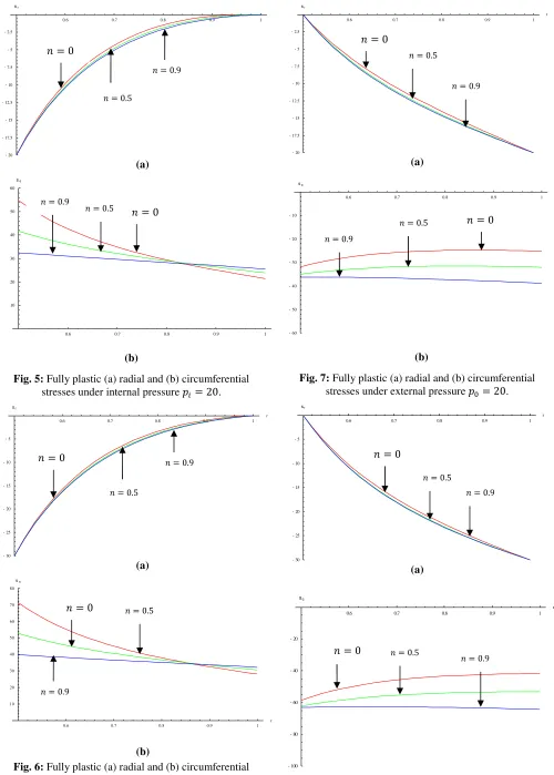
Fig. 5: Fully plastic (a) radial and (b) circumferential stresses under internal pressure = 20.
(a)
(b)
(b)
Fig. 6: Fully plastic (a) radial and (b) circumferential stresses under internal pressure = 30.
(a)
(b)
Fig. 7: Fully plastic (a) radial and (b) circumferential stresses under external pressure = 20.
(a)
(b)
Fig. 8: Fully plastic (a) radial and (b) circumferential stresses under external pressure = 30.
0.6 0.7 0.8 0.9 1
-20 -17.5 -15 -12.5 -10 -7.5 -5 -2.5 sr
0.6 0.7 0.8 0.9 1
10 20 30 40 50 60
sq
0.6 0.7 0.8 0.9 1
r
-30 -25 -20 -15 -10 -5 sr
0.6 0.7 0.8 0.9 1
r 10
20 30 40 50 60 70 80 sq
0.6 0.7 0.8 0.9 1
r
-20 -17.5 -15 -12.5 -10 -7.5 -5 -2.5 sr
0.6 0.7 0.8 0.9 1
r
-60
-50
-40
-30
-20
-10
sq
0.6 0.7 0.8 0.9 1
r
-30
-25
-20
-15
-10
-5
sr
0.6 0.7 0.8 0.9 1
r
-100
-80
-60
-40
-20
sq
݊ = 0
݊ = 0 ݊ = 0
݊ = 0
݊ = 0 ݊ = 0
݊ = 0 ݊ = 0
݊ = 0.5
݊ = 0.5
݊ = 0.5
݊ = 0.5
݊ = 0.5
݊ = 0.5
݊ = 0.5
݊ = 0.5
݊ = 0.9 ݊ = 0.9
݊ = 0.9
݊ = 0.9
݊ = 0.9
݊ = 0.9
݊ = 0.9
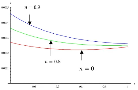
[image:4.595.310.547.399.758.2]Fig. 9: Displacement in the radial direction under internal pressure = 20 Pa and external pressure = 30 Pa with
rotation.
Fig. 10: Displacement in the radial direction under internal pressure = 30 Pa and external pressure = 20 Pa with
rotation. IVCONCLUSION
Elastic-plastic stresses have been derived for an annular disk with variation in thickness and Young’s modulus. For higher pressure a significant increase is seen for both radial and tangential stresses. Radial displacement with variation in radii is plotted under the effect of pressure. It is seen that with increase in geometric parameter, the resisting stress decreases.
REFERENCES
[1] F. Takashi and N. Naotake, “Analysis of thermal stress in a plate of functionally graded material”, JSAE Review, vol. 16, no. 3, pp. 263 – 268, 1995.
[2] Z. H. Jin and G. H.Paulino, “Transient thermal stress analysis of an edge crack in a functionally graded material”, International Journal of Fracture, vol. 107, no. 1, pp. 73 – 98, 2001.
[3] R. M. Mahamood, E. T. Akinlabi, M. Shukla and S. Pityana, “Functionally graded material: An Overview”, Proceedings of the World Congress on Engineering, London, vol. III, July 4 – 6, 2012. [4] S. K. Bohidar, R. Sharma and P. R. Mishra, “Functionally Graded
Materials: A critical review”, International Journal of Research (IJR), vol. 1, Issue 7, pp. 289 – 301, 2014.
[5] L. H. You, X.Y, You, J. J. Zhang and J. Li , “On rotating circular disc with varying material properties”, ZAMM, vol. 58, pp. 1068 – 1084, 2007.
[6] L.H. You, J. X. Wang and B.P. Tang , “Deformations and stresses in annular disks made of functionally graded materials subjected to internal and/or pressure”, Meccanica, vol. 44, pp. 283 – 292, 2009.
[7] J. N. Sharma, D. Sharma and S. Kumar , “Stress and strain analysis of rotating FGM thermoelastic circular disk by using FEM”,
International Journal of Pure and Applied Mathematics, vol. 74, no. 3, pp. 339 – 352, 2012.
[8] M. Garg, B. S.Salaria and V. K. Gupta, “Effect of thermal gradient on steady state creep in a rotating disc of variable thickness”, 6th
International Conference on Creep, Fatigue and Creep-Fatigue Interaction [CF-6], vol. 55, pp. 542 – 547, 2013.
[9] M. Sahni and R. Sahni, “Rotating Functionally Graded Disc with Variable Thickness Profile and External Pressure”, Elsevier Procedia Computer Science, vol. 57, pp. 1249 – 1254, 2015.
[10] C. Rajeshwari, R. K. Krishna and K. Rambabu, “Stress analysis of functionally graded disc brake subjected to mechanical loading”,
International Journal of Modern Engineering Research (IJMER), vol. 5, no. 1, pp. 1 -8, 2015.
[11] H. Callioglu, E. Demir and M. Sayer, “Thermal stress analysis of functionally graded rotating discs”, Scientific Research and Essays, vol 6, no. 16, pp. 3437 – 3446, 2011.
0.6 0.7 0.8 0.9 1
r 0.00005
0.0001 0.00015 0.0002 0.00025 u
0.6 0.7 0.8 0.9 1
r 0.0001
0.0002 0.0003 0.0004 0.0005 u
݊ = 0 ݊ = 0
݊ = 0.5
݊ = 0.5 ݊ = 0.9
[image:5.595.58.283.268.415.2]