Abstract—This paper proposes a novel incoherent transceiver structure for an optical code-division multiple-access (OCDMA) system that employs polarization shift keying (PolSK). The architecture has been accurately analyzed considering optical amplifier spontaneous emission (ASE) noise, electronic receiver noise, photo-diode shot-noise and mainly multiple-access interference (MAI). The application of optical tapped-delay lines (OTDL) in the receiver as the CDMA-decoder has also been investigated. In terms of spreading code, double-padded modified prime code (DPMPC) has been utilized. The results indicate that the proposed architecture is power efficient and also enhances the system capacity. The constant-envelop optical beam in PolSK modulation makes the system have immunity against the self- and cross-phase modulations. This scheme can be promising for long-haul high-speed transmissions over the OCDMA network.
Index Terms—Multiple-access interference, optical CDMA, polarity shift keying, prime code families
I. INTRODUCTION
Bandwidth-hunger world nowadays demands higher bit-rate and ultra-fast services such as video-on-demand (VoD) and streaming over the Internet protocol (SoIP) e.g. IPTV. Due to tremendous resources of bandwidth and extremely low loss, fiber-optic can be the best physical transmission medium for telecommunications and computer networks. Unlike conventional time-division multiple-access (TDMA) and wavelength-division multiple-access (WDMA) techniques, code-division multiple-access (CDMA) can make full use of the huge bandwidth in the fiber-optic. Meanwhile, it has the potential to support random access protocol, different services with different data-rates and bursty traffics.
Optical CDMA (OCDMA) has been proposed as an access protocol that takes advantage of the excess bandwidth particularly in single-mode fiber-optic (SMF). It provides multi-channel communications over a single frequency band. Accordingly, signals must be designed to reduce mutual interferences. This can be achieved by subdividing each data into a number of binary chips. The chip sequences constitute a code that permits a bit-stream broadcasted on a network to be selected by means of a correlation process at the receiver destination. A large number of chip sequence signatures can be assigned to different users, in the process of which the set of optical signatures essentially becomes a set of address codes for the network users.
Incoherent OCDMA technique inherently suffers from multiple-access interference (MAI) that requires estimation and removal through cancelation techniques or higher order modulations [1]-[4]. In the past few years, advances in
Authors are with the Department of Electronic, Electrical and Computer Engineering, University of Birmingham, B15 2TT, UK (e-mails: [email protected] and [email protected]).
photonics technology made it possible for incoherent scheme to approach the sensitivity performance of coherent ones. Hence, there has been a considerable shift of interest from coherent to incoherent scheme on the part of both research and industry, due to its simple architecture and cost effectiveness.
Polarity shift keying (PolSK) is the only modulation that takes advantages of vector characteristic of lightwave. It has been experimentally reported in [5] that PolSK has insensitive behavior to (i) phase noise, (ii) polarity fluctuations, (iii) self- and cross-phase modulations due to the constant-power envelop of the lightwave. A comprehensive set of results in [5] and [6] showed that the performance of the binary PolSK is approximately 3dB better than intensity modulation (on the peak optical power) of other PolSK or equivalent phase shift keying (PSK) modulations. It has very low sensitivity to fiber dispersions in which elevates the system performance accordingly. PolSK encodes the information on a constellation of signal points in the space of the Stokes parameters which are the coordinates of the signal’s states of polarity (SOP) over the Poincaré sphere [6]. In general, each signal point corresponds to a given SOP and a given optical power. To perform PolSK detection avoiding optical birefringence compensation, it is necessary to use a receiver that extracts the Stokes parameters of the incoming lightwaves [6]. Additionally, the advantages of PolSK over OCDMA have been reported in [7] and [8].
In this paper, we propose a novel OCDMA architecture design based on polarity modulation. The application of optical tapped-delay line (OTDL) as the incoherent OCDMA decoder is also investigated. It is assumed that the signal is degraded by (i) fiber amplifier spontaneous emission (ASE) noise, (ii) electronic receiver noise (iii) photo detectors (PD) shot-noise and (iv) mainly MAI. For optical signature sequences, we have used a coding scheme based on double-padded modified prime code (DPMPC). It has been extensively introduced and employed in pulse-position modulation (PPM) [2], in overlapping PPM [4], in coherent heterodyne [9] and homodyne [10]-[12] schemes, and also in frequency modulated OCDMA system [13] with new MAI cancellation technique [14].
This paper is organized as follows. The proposed transmitter architecture is discussed in the following section. Section III analyses the receiver structure and operation resulting in overall system signal-to-noise ratio (SNR). The architecture is evaluated and the results are demonstrated based on the system performance in terms of bit-error rate (BER) in section IV. Finally the study is concluded.
II. TRANSMITTER ARCHITECTURE
A generic transformation of the SOP of a fully polarized lightwave, propagating along the z-axis which preserves the
M. M. Karbassian,
Member, IAENG
and H. Ghafouri-Shiraz
degree of polarization, is explained as follows. Let
E
(
t
)
and)
(
t
E
′
be the electromagnetic field vectors before and after the transformation (i.e. modulation) respectively, and given as follow:t j y
x
t j y
x
e y t E x t E t E
e y t E x t E t E
ω ω
) ) ( )
( ( ) (
) ) ( )
( ( ) (
′ ′ + ′ ′ = ′
+ =
(1)
where
ω
is the optical angular frequency,Ex(t) andE
y(
t
)
are(
x
,
y
)
-components of electric field before transformation andE
′
x(
t
),
E
y′
(
t
)
are(
x
,
y
)
-components of electric field after transformation. Thus, we have:
=
′
′
)
(
)
(
)
(
)
(
t
E
t
E
t
E
t
E
y x
y x
Q
(2) where Q is a complex Jones matrix with unit determinant. A subset of Jones matrices, called the set of matrices of birefringence or optical activity, does not only preserve the degree of polarizations, but also has the additional feature of preserving two orthogonal fields (according to the Hermitian scalar product) [15]. Matrices of this kind are complex unitary matrices with unit determinant. Throughout this paper we strictly refer to theJj as subset of Q=[J0 ... Jj ... Jk−1].By using the Jones representation, the field can be represented by the vector J=[Ex Ey]Tand the intensity of the beam can be normalized so that Ex 2 + Ey 2 =1. Two SOPs represented by
J
1 andJ
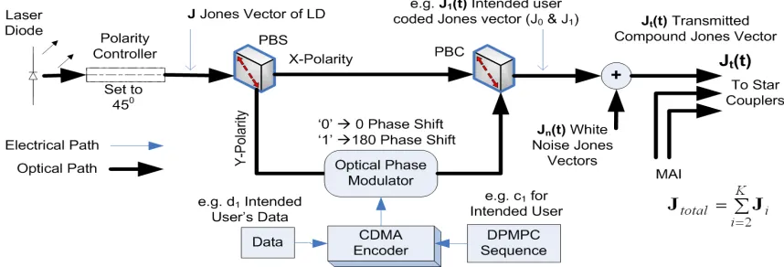
2 are orthogonal if their inner product is zero. Any SOP can be transformed into another by multiplying it by a Mueller matrix. Ref. [15] gives a list of Mueller matrices that are required for SOP processing (i.e. polarizers, rotators and retarders). In PolSK, the angle of one polarization component is switched relative to the other between two angles; therefore, binary data bits are mapped into two Jones vectors. A block diagram of the proposed PolSK-OCDMA transmitter is illustrated in Fig. 1. The light source is a highly coherent laser with a fully polarized SOP. If a nonpolarized source is used, then a polarizer can be inserted after the laser source. The light beam first passes through the polarity controller that sets the polarity to an angle of45
°
for simplicity. Then, the lightwave gets divided through polarity beam splitter (PBS) to become SOP-encoded in PolSKmodulator which switches the SOP of the input beam between two orthogonal states (i.e.
0
°
and180
°
at the phase modulator in Fig. 1) N times per bit according to an externally supplied code (i.e. DPMPC) that spreads the optical signal into CDMA format. Thereafter, the PolSK-OCDMA modulated signals are combined through polarity beam combiner (PBC) and transmitted. It is also displayed in Fig. 1 that for a K-user system with the first user as the desired one (for example), thei
th user SOP-encoded signal can be written as:
= ⊕
= ⊕ =
1 ) ( ) (
0 ) ( ) ( )
(
1 0
t c t d if
t c t d if t
i i
i i i
J J
J (3)
where
d
i(
t
)
is the data signal with symbol duration ofT
s,)
(
t
c
i is the N-chip code sequences (DPMPC) signal with chip duration ofT
c andd
i(
t
),
c
i(
t
)
∈
{
0
,
1
}
;⊕
denotes the signal correlation. As the emitted light is initially (linearly) polarized at an angle of45
°
, thereforeT
] 1 1 [ 2 1 0 =
J and [ 1 1]T
2 1
1 = −
J [8]. In
other words, we have:
− =
=
1 1
1 1
2 1 ] [J0 J1
Q (4)
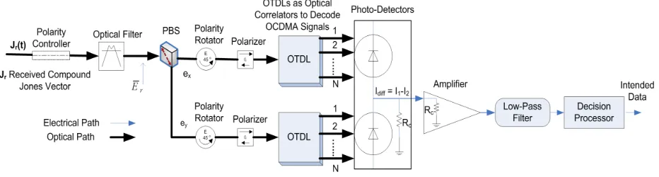
Therefore, the polarity-modulated signal travels a distance of L [km] through an optical SMF. Consequently, the SOP-encoded signal undergoes several impairments such as attenuation, dispersion, polarization rotation and fiber nonlinearity. At the receiver end shown in Fig. 2, the SOP rotation is compensated by the polarization controller whose function is to ensure that the received signal and the optical components at the receiver have the same SOP reference axis.
III. RECEIVER ARCHITECTURE AND ANALYSIS We previously discussed the configuration of the transmitter. Now we consider the alignment and analysis of the received optical signal. The electric field of the received polarity-modulated lightwave for K number of users can be expressed as [7]:
−
− =
′ ∑
= K i
i s T
i i
t c iT t u t d
t d t
E t
E
1
) ( ). (
) ( 1
) ( )
( Re )
( Q (5)
The channel is represented by the Jones matrix Q and
[image:2.595.88.517.58.204.2]equipower signal constellations have been considered, both orthogonal components are assumed to be equally attenuated. Thus, these terms can be included in the constant amplitude of the electric field
E
(
t
)
which neglects a loss of orthogonality on the channel. While switching time in SOP (i.e. bit-rate) is much slower than the chip-rate, the elements of the Jones matrix can be understood as time-independent (i.e.T
c<<
T
s). The x-component of the received electric field vector based onQ
=
[
J
0J
1]
(see (4)) is:[
]
− × − + = ′∑
= ) ( ). ( )) ( 1 ( ) ( ) ( Re ) (1 0 1
t c iT t u t d t d t E t E i s T K i i i
x J J
(6)
Thus, orthogonal components of the
i
th user are given as ) ( ) ( ) ( )(t 0d t c t E t
Exi = J i i and Eyi(t)=J1(1−di(t))ci(t)E(t) and the
(
x
,
y
)
-components of received modulated signal are [7]: ) cos( ) ( 2 ) ( ) ( ) ( ) ( 2 ) ( ) ( ) ( 1 xi K i s T yi xi i i yi xixi u t iT
t E t E t d t c t E t E t
E ϕ
− − + + = ′ ∑ = (7) ) cos( ) ( 2 ) ( ) ( ) ( ) ( 2 ) ( ) ( ) ( 1 yi K
i T s
yi xi i i yi xi
yi u t iT
t E t E t d t c t E t E t
E ϕ
− + + − = ′ ∑ =
where
ϕ
xi andϕ
yi describe the frequencies and phases of transmitting lasers in a general form ofϕ
=
ω
t
+
θ
. Based on the concept of CDMA, the field vectors of all Ktransmitters are combined and multiplexed over the same channel. Thus, the overall channel field vector can be expressed as: ∑ = ′ = K i i Channel E t
E
1 )
[image:3.595.66.532.60.185.2]( (8) Figure 2 illustrates the application of the OTDLs used as
the optical correlator in this incoherent PolSK-OCDMA system. The delay coefficients in OTDLs are designed in such a way to make them perform as a CDMA chip-decoder in both branches. Additionally, OTDL in lower branch must be set up with complement of code used in upper branch to decode other symbol (i.e. ‘1’). It can be observed from Fig. 2 that OTDLs’ outputs contain N chip pulses that can be assumed as a parallel circuit of many single PDs so that their currents are added and no interference between the OTDL pulses is possible. The signals are photo-detected in the balanced-detector arrangement to generate the differential electrical current (
I
diff=
I
1−
I
2) ready for data-extraction in decision processor unit. The total upper branch current (i.e.x-component) considering all chip currents after photo-detection is then obtained as:
dt t E t E nT t c t d t E t E nT c I K i xi yi xi c i i yi xi s T t N n c − − + + + ℜ = ∑ ∫ ∑ = = = 2 1 0 1 0 ) cos( 2 ) ( ) ( ) ( ) ( 2 ) ( ) ( 2 1 ) ( ϕ (9)
where ℜ is responsivity of the PD,
c
i(
t
−
nT
c)
is theth
n
chip of assigned spreading code of thei
thuser. By further simplification, the upper PD currentI0 can be modified as shown at the bottom of the page. Since PD frequency response behaves similar to a low-pass filter, both the terms cosϕxi in the first element and cos(ϕxi +ϕxj) in the second element of (10) are filtered out as they are outside of the PD frequency range. Furthermore, the term cos(ϕxi−ϕxj) can also be removed provided thatc xj
xi ϕ ω
ϕ − >> where ωc is the cut-off frequency of the PD. Therefore, the total current of upper branch can be expressed as:
Fig. 2. Proposed architecture of incoherent polarity modulated optical CDMA receiver
(
)
(
)
(
E t E t d t c t nT E t E t)(
)
dtt E t E nT t c t d t E t E nT c dt t E t E nT t c t d t E t E nT c I xj xi xj xi yj xj c j j yj xj s T t N n K i K i j j yi xi c i i yi xi c s T t N n K i xi yi xi c i i yi xi c − + + − − + + × − − + + + ℜ + − − − + + + ℜ = ∫ ∑ ∑ ∑ ∫ ∑ ∑ = = = ≠ = = = = ) ( cos ) ( cos )) ( ) ( )( ( ) ( ) ( ) ( )) ( ) ( )( ( ) ( ) ( ) ( 2 1 ) ( 8 ) 2 cos 1 ( )) ( ) ( )( ( ) ( ) ( ) ( 2 1 ) ( 4
0 1 1 1
0 1 1
− − + + + ℜ = ∑ ∑ = = )) ( ) ( )( ( ) ( ) ( ) ( 2 1 ) ( 4 2 2 2 1 2 1 0 t E t E nT t c t d t E t E nT c I yi xi c i i yi K i xi c N n (11)
The Stokes parameters are defined as:
) ( ) ( ) ( ) ( 2 2 1 2 2 0 t E t E S t E t E S yi xi i yi xi i − = +
= (12)
where Si0 refers to signal intensity part, generated in upper branch of polarity modulator at the transmitter while
1 i
S
refers to the linear polarized part, generated in lower branch containing data (see Fig. 1). Thus, (11) can be rewritten as:(
)
∑
∑
= = − + + ℜ = N n Ki i i i c i
c S d t c t nT S
nT c I 1 1 1 0 0 ) ( ) ( 2 1 ) ( 4 (13)
Similarly the total current of the lower branch (i.e.
y-component) can be derived as:
(
)
∑ ∑ = = − + − ℜ = N n K i i c i i ic S d t c t nT S
nT c I 1 1 1 0
1 () ( )
2 ) ( 1 4 (14)
Thus, the balanced-detector output (I =I0−I1) is then derived as:
(
( ) ( ))
( ) ) ( 4 1 1 0 1 t n S nT t c t d S nT c I Ki i i i c i
N n c + − + ℜ =
∑
∑
= = (15) wheren
(
t
)
=
n
x(
t
)
+
j
n
y(
t
)
represents the total filtered Gaussian noise with independent Gaussian processes of)
(
t
n
x ,n
y(
t
)
with equal variance of σ 2 that includes: (i) optically filtered ASE noise with variance of ASE N0Bo2
2 = σ
whereN0is the (unilateral) power spectral density (PSD) of the white ASE noise arriving on each polarization and
B
ois the optical filter bandwidth; (ii) the PD shot-noise with electric current variance of iav2 =2eiBo wherei
av is theaverage photo-current; (iii) electronic receiver noise current (i.e. thermal noise) at the low-pass filter with variance of
el b LP B R T k . 2 2 =
σ where R is the filter direct-current (dc) equivalent impedance, T is the absolute temperature and
k
bis the Boltzmann constant and
B
el is the filter bandwidth. Thus the overall variance of additive noise ofn
(
t
)
can be represented as: 2 2 2 2 )(t ASE LP
n i σ σ
σ = + + (16) By considering the first user as the intended user then we can modify the differential output current, i.e. (15), as:
) ( ) ( ) ( ) ( 4 ). ( ) ( ) ( 4 ) ( 4 1 2 1 1 1 1 1 1 1 0 1 t n S t d nT t c nT c S t d nT t c nT c nT c S I i i K
i i c
N n c N n c c N n c + − ℜ + − ℜ + ℜ = ∑ ∑ ∑ ∑ = = = = (17)
The first element in (17) is a dc current that needs estimation and removal in the balanced-detector. The second element represents the intended data mixed with its assigned spreading code auto-correlation and polarization while the third element assumes the interference (i.e. MAI) caused by other transmitters and the last one is the noise. Thus, the system SNR can be expressed as:
2 ) ( 2 1 2 1 2 1 1 1 1 1 ) ( ) ( ) ( 4 ). ( ) ( ) ( 4 t n i i K i c i N n c c N n c S t d nT t c nT c S t d nT t c nT c SNR σ + − ℜ − ℜ = ∑ ∑ ∑ = =
= (18)
Both the auto- and cross-correlation of the DPMPC can be expressed respectively as [8-11]:
( )1( ) 2
1 + = −
∑
= P nT t c nT c c N n c (19) ) ( ) (1 i c
N
n l c
li c nT c t nT
X = ∑ −
=
(20) where P is a prime number.
The cross-correlation, i.e. (20), probability density function (PDF) can be obtained from the independent values of random variable
X
li. The in-phase cross-correlation value of DPMPC is either zero or one depending on whether the codes are in the same group or from the different groups [2]. Obviously, the zero value does not cause the interference due to perfectly orthogonal sequences, while the one value causes the interference which is only among intended user and (P
2−
P
) users from the different groups (i.e.P
2 whole2 4 6 8 10 12 14 16 18 20
10-12 10-10 10-8 10-6 10-4 10-2 100
Single User SNR, Sdb
B it E rr o r P ro b a b ili ty Code-Length=399 & Full-Load=342 for P=19
%10 Full-Load %15 Full-Load %20 Full-Load %25 Full-Load
[image:4.595.59.278.64.235.2]1e-9
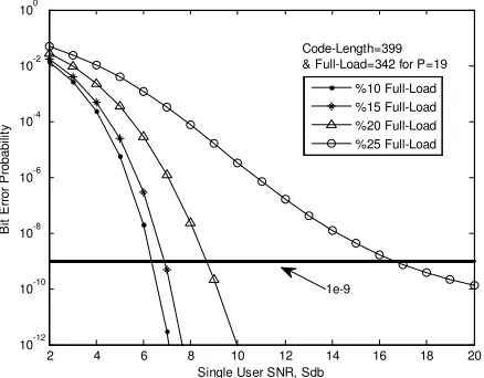
Fig. 3. BER performance of the transceiver versus single-user SNR, Sdb
40 50 60 70 80 90 100 110 120
10-12 10-10 10-8 10-6 10-4 10-2 100
No. of Simultaneous Users, K
B it E rr o r P ro b a b ili ty , P b Code-Length=399 & Full-Load=342 for P=19
Sdb = 8dB Sdb = 10dB Sdb = 12dB Sdb = 14dB
1e-9
[image:4.595.58.278.269.439.2]sequences and P sequences from the same group of intended user which are orthogonal) [4]. As, the cross-correlation values are uniformly distributed among interfering users, thus the PDF of w, realization of
X
li, is:P
P
i
i
w
P
−
=
=
)
2(
(21) whereP
(
w
=
i
)
is the probability that w assumes the value i(the number of actively involved users in the transmission). Therefore, by substituting (19) and (21) into (18) and a little further calculation, the system SNR can be simplified as:
2 2 1 1 2 1
2 ) ( 2
2
) 2 ( ). (
4
) 2 )( (
2
) 1 (
1 )
(
+ ℜ
+
+ −
− =
P S t d P
P P
K K K
SNR
t n
σ
(22)
Note that 2
) ( 2 2
1 1 2
1 ( ). ( 2) 4
) 1
( d t S P n t
SNR =ℜ + σ which
equals
E
b/
N
0 whereE
b is the energy of one bit andN
0is the noise PSD, denotes the single-user SNR. Expression (22) is one of the main results of this paper as it represents the SNR of polarity-modulated OCDMA system.IV. DISCUSSION OF RESULTS
BER estimation of binary PolSK modulation has already been evaluated in [6] and [15]. Here, the numerical results of the BER performance of the proposed transceiver based on the above detailed analysis, resulted in the OCDMA system SNR, are demonstrated and discussed.
Figure 3 shows the BER of this system versus the single-user SNR (shown on Figs. by Sdb). Different trends like 10%, 15%, 20% and 25% of full-load (i.e.
P
2−
P
interfering users [2]) as the number of simultaneous active users where P=19 have been evaluated in this analysis. As illustrated in Fig. 3, the system that can manage 25% of full-load is able to provide BER =10−9withSdb=16.5db;
whereas for Sdb=8.5dbthe system can support 20% load which is still superior enough to deliver the network services. Furthermore, the system can tolerate 15% load with onlySdb=7db. It is indicated that the delivering network services under these conditions is very power efficient. Although for supporting greater number of users, higher values for P and Sdb are recommended.
Figure 4 also indicates the BER performance versus the number of simultaneous users (K) for the above system. As it is observable from Fig. 4, when the number of users increases, the BER also increases due to growing interferences. The system employed Sdb=14dbcan tolerate 80 simultaneous users where P=19 which is equal to 24% of full-load. While 73 users (21% of full-load) are guaranteed very consistent communication link ( 9
10− ≤
BER ) with onlySdb =10db, which refers to cost-effective design as less-power consumed. To compare the results with those in [7] and [8], the proposed architecture can tolerate greater number of users with less Sdb. On the other hand, the results achieved in this analysis are with the code-length of 399 (i.e. for P=19 [2]) which is much less than those employed in [7] and [8] (Gold sequences with lengths of 511 and 1023). That implies the proposed structure can provide higher system throughput as the code-length is smaller.
V. CONCLUSION
This paper has proposed and evaluated novel transceiver architecture of incoherent optical polarity-modulated CDMA system. The application of OTDL in a dual-balanced configuration as the CDMA-decoder has also been investigated. From a detailed analysis, we have obtained the system SNR and accordingly demonstrated the overall BER performance. The performance of PolSK over OCDMA in cooperation with DPMPC as the spreading code has been demonstrated taking into account the effects of optical ASE noise, electronic receiver noise, PDs shot-noise and mainly the multi-user interferences. The derived results indicate that the architecture can reliably and power-efficiently accommodate great number of simultaneous users. In other words, the proposed architecture will cover extra implementation costs through less power consumption regime and more subscribers.
REFERENCES
[1] F. Liu, M. M. Karbassian and H. Ghafouri-Shiraz, “Novel family of prime codes for synchronous optical CDMA”, J. Optical and Quantum Electronics, vol. 39, no. 1, pp. 79-90, Jan. 2007
[2] M. M. Karbassian and H. Ghafouri-Shiraz, “Fresh prime codes evaluation for synchronous PPM and OPPM signaling for optical CDMA networks”, J. Lightw. Tech., vol. 25, no. 6, pp. 1422-1430, June 2007
[3] H. Ghafouri-Shiraz, M. M. Karbassian, F. Lui, “Multiple access interference cancellation in Manchester-coded synchronous optical PPM-CDMA network”, J. Optical and Quantum Electronics, vol. 39, no. 9, pp. 723-734, July 2007
[4] M. M. Karbassian and H. Ghafouri-Shiraz, “Capacity enhancement in synchronous optical overlapping PPM-CDMA network by a novel spreading code”, Proc. of GlobeCom‘07, pp. 2407-2411, Nov. 2007 [5] S. Benedetto et al., “Coherent and direct-detection polarization
modulation system experiments,” in Proc. ECOC’94, Sept. 1994. [6] S. Benedetto, R. Gaudino and P. Poggiolini, “Direct detection of
optical digital transmission based on polarization shift keying modulation”, IEEE J. Selected Areas in Comms., vol. 13, no. 3, pp. 531-542, April 1995
[7] K. Iversen, J. Mueckenheim and D. Junghanns, “Performance evaluation of optical CDMA using PolSK-DD to improve bipolar capacity”, SPIE Proc., vol. 2450 (Amsterdam), pp. 319-329, 1995 [8] N. Tarhuni, T. O. Korhonen and M. Elmusrati, “State of polarization
encoding for optical code division multiple access networks”, J. of Electromagnetic Waves and Applications (JEMWA), vol. 21, no. 10, pp. 1313-1321, 2007
[9] M. M. Karbassian and H. Ghafouri-Shiraz, “Performance analysis of heterodyne detected coherent optical CDMA using a novel prime code family”, J. Lightw. Technol., vol. 25, no. 10, pp. 3028-3034, Oct. 2007 [10] M. M. Karbassian and H. Ghafouri-Shiraz, “Phase-modulations
analyses in coherent homodyne optical CDMA network using a novel prime code family”, Proc. IAENG WCE 2007, pp. 358-362, July 2007 [11] M. M. Karbassian and H. Ghafouri-Shiraz, “Performance analysis of
unipolar code in different phase modulations in coherent homodyne optical CDMA”, IAENG Engineering Letters, vol. 16, no. 1, pp. 50-55, March 2008
[12] M. M. Karbassian and H. Ghafouri-Shiraz, “Study of phase modulations with dual-balanced detection in coherent homodyne optical CDMA network”, J. Lightw. Technol., in press [13] M. M. Karbassian and H. Ghafouri-Shiraz, “Novel channel
interference reduction in optical synchronous FSK-CDMA networks using a data-free reference”, J. Lightw. Technol., vol. 26, no. 8, pp. 977-985, April 2008
[14] M. M. Karbassian and H. Ghafouri-Shiraz, “Frequency-shift keying optical code-division multiple-access system with novel interference cancellation”, Microw. and Opt. Techno. Lett., vol. 50. no. 4, pp. 883-885, April 2008