Volume 2, Issue 3, 2015
65
Available online at www.ijiere.com
International Journal of Innovative and Emerging
Research in Engineering
e-ISSN: 2394 - 3343 p-ISSN: 2394 - 5494
VLSI Based 16 Bit ALU with Interfacing Circuit
Chandni N. Naik
a, Vaishnavi M. Velvani
a, Pooja J. Patel
a, Khushbu G. Parekh
aa Student of Electronics & Communication GEC/GTU Bharuch, Gujarat, India
ABSTRACT:
The ALU is one of the most important module in a CPU and it can be modified during most instruction executions. So more bit of operation of the ALU is important task. In this project 16 bit ALU is designed using VHDL and it is interfaced with RAM and ROM. This design is then implemented in Xilinx. After making an ALU, interfaced it with RAM and ROM. All results are shown as waveforms in Xilinx software. This project helps to speed up the CPU. It can work fast and less instructions are required for the same operation compare to less bit ALU processor.
Keywords:ALU,VHDL,16 bit, interface RAM & ROM.
I. INTRODUCTION
In market 8 bit ALU is used. We are going to make 16-bit ALU using VLSI. This ALU operate on 16-bit input. It performs arithmetic & logical operations. Then give appropriate output. The ALU is one of the most important modules in a CPU and is modified during most instruction executions. Hence the power consumption of the ALU is a major factor. In this project a low power 16 bit ALU is designed using VHDL. Then RAM and ROM are interfaced with this ALU. VHDL language is used for making ALU.VHDL is an industry standard language for the description, modeling and synthesis or simulate of digital circuits and systems.
The Arithmetic Logic Unit (ALU) is the heart of a CPU. This allows the computer to add, subtract, multiplication and division and to perform basic logical operations such as AND, OR, XOR, XNOR, NAND and inverter etc. Since every computer needs to be able to do these functions, they are always included in a CPU these functions. An ALU is a combinational logic circuit that can have more inputs and only one output. ALU’s output is dependent only on inputs which are applied at that instant and not on past conditions. A simple ALU in its basic form consists of two inputs for the operand data, one input for selecting the required operation and one output for the result according to selected operation.
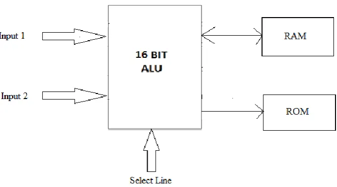
II. BLOCK DIAGRAM
66
III.WORKING
In this block diagram, one 16 bit ALU is used for performing 16 bit operations. There are two data inputs and one select line. According to select line input appropriate operation is performed between two inputs. Output of this 16 bit ALU is connected with RAM and ROM.
Table 1. Function Table
For example, if select line input is 0001, then subtraction is performed between two inputs. According to select line all operations are performed. This table shows the particular operation for particular selection line input.
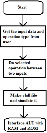
IV.FLOWCHART
As shown in flow chart, first we get two input data and one operation selection input from user. Then according to above table proper operation is done between two inputs as per selection line input. Then this output is sent to output line of ALU. Data input is in 16 bits. After completed this process successfully, we VHDL program file to simulate it on Xilinx software. If this file successfully simulated then we interface this ALU with RAM and ROM to save the output data of ALU. Simple design flow shown here. It shows procedure of project in simple way.
Figure 2. Flow Chart
S(0) S(1) S(2) S(3) Operation
0 0 0 0 A+B+Cin
0 0 0 1 A-B-Cin
0 0 1 0 A*B
0 0 1 1 A/B
0 1 0 0 AND
0 1 0 1 OR
0 1 1 0 NOT
0 1 1 1 XOR
1 0 0 0 NAND
1 0 0 1 NOR
1 0 1 0 XNOR
1 0 1 1 SHIFT LEFT
1 1 0 0 SHIFT RIGHT
1 1 0 1 SHIFT LEFT WITH CARRY
1 1 1 0 SHIFT RIGHT WITH CARRY
Volume 2, Issue 3, 2015
67
V. Related Work A. Adder
Figure 3. Adder[4]
A full adder is a logical circuit that performs an addition operation on three binary digits. The full adder produces a sum and carries value, which are both binary digits. It can be combined with other full adders and then it can be increased the number of bit of addition operation.
B. Subtractor
Full sub tractor can be cascaded to form ripple-borrowsubtractions in the same way as like full adders are cascaded to form ripple-carry adders for 16 bit . Figure 3 illustrates an one-bit full adder and number of bits can be increased using cascading circuit. Same way cascaded sub tractor can be design using same method using full sub tractor.
(a) – (b) = (a) + (-b)
C. Multiplier
Figure 4. Multiplier[5]
Figure 4. shows the 64-bit multiplication. We have used this logic for designing our multiplier. The multiplication is done through repeated additions logic. Partial products are taken in this addition logic. The partial products depend on the multiplier bit being considered. If 1 is multiply with 0 then answer is 0. 1 multiply 1 is equals to 1. This logic works on multiplier. Multiplication answer require 32 bit output port. So 16 bit multiplication require 32 bit answer.
D. Divider
68 The algorithm has main three steps which should be followed. In the first step divisor number is subtracted from dividend number stored in register. If the result is positive, then the divisor is less than or equal to dividend, so we generate a ‘1’ in the quotient shifter. If the result is negative we stop the process of division and show the result of quotient and reminder. If not divisor is again subtracted number from the remainder register data number and quotient should be incremented by ‘1’. This is repeated till remainder number becomes less than the divisor number data. The remainder number and the quotient number will be found in their appropriate registers after the process is completed. Here figure shows the shifting logic for division operation. We use this logic for our design.
E. RAM and ROM:
RAM and ROM are the memories. From the ROM we can only view the information saved in it. We have to give input address to the ROM. According to this address, we can see the saved information at that address in ROM. In RAM, we can save output to the memory and read the information saved in memory. So read and write operation is done giving proper input to it. Both memories are connected or interfaced with ALU unit to save the output and to take the input. Both memories are used to save the 16 bit data.
.
V. SIMULATIONRESULTS
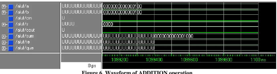
Figure 6. Waveform of ADDITION operation
Figure 6. shows simulation result of 16 bit addition waveform in xilinx software. If op or S input is “0000” then addition is performed between A and B input.
Figure 7. Waveform of Multiplication operation
This figure 7 shows the simulation result of 16 bit Multiplication operation.
Figure 8. Waveform of Division operation
Volume 2, Issue 3, 2015
69
VIII.CONCLUSIONS
This 16-bit ALU will perform 15 different types of arithmetic, logical and shifting operations. When more bits are used, big calculations are become faster and simple. It requires less instruction compare to less bit ALU. The key advantage of using VHDL is that it gives the idea about the behavior of our design before implementing it on hardware. We can easily synthesis it on Xilinx software and find out errors according to logic of program. Xilinx and VHDL are standard for every industry. We can also synthesis the project in implementing way very easily using Xilinx. So this ALU is very useful to making high speed computer, microcomputer, special application computer for scientists. This ALU is also used in special high speed applications.
ACKNOWLEDGMENT
We would you like to express the deepest gratitude to the following that without their help, this project would not possible. First to the parents of our who are always there with continuing support, morally and financially. To Mrs. N. K. Prajapati and Mr. S. J. Davda, the our teacher, ho always leading and helping our to finish this project. To our friends and classmates, especially to Helina Patel, Neha Mistry and Hiral Davda who are giving their comments and suggestion on how this project can improve. And most of all to God, who gave us enough knowledge to think about this project and the perseverance and determination to continue doing this project in spite of the struggles that came our way.
REFERENCES
[1]Paul P. Chu, Deepak R.Mithani, “32 bit extended function Arithmetic-logic unit on single chip”, U.S. Patent Document, Vol. 3, Issue 7, July 1984.
[2]Rahul R.Balwaik, Yogesh M. Jain, Amutha Jeyankar, “Vlsi design of 16-bit processor”, International Journal of VLSI and Embedded Systems-IJVES ISSN-2249, Vol04, June 2013
[3]Nilam Patel, Prof. J.H.Patil, “FPGA Based Implementation of 16 bit RISC Microcontroller ”, International Journal of scientific Research, Volume 4, Issue1, January 2015
[4]John,”Circuit Today”,Circuit today Store, April 17, 2010
[5]Girdhar Gopal, “http://girdhargopalbansal.blogspot.in/2013/10/computer-arithmetic.html”, girdhargopalbansal. blogspot, 10/06/2013
![Figure 4. Multiplier[5]](https://thumb-us.123doks.com/thumbv2/123dok_us/8873767.1815611/3.595.144.458.385.533/figure-multiplier.webp)