Volume 66, 2019, Pages 32–43
Proceedings of 6th International OM-NeT++ Community Summit 2019
Simulation Speedup in OMNeT++ Using Contact Traces
Thenuka Karunathilake, Asanga Udugama, and Anna F¨
orster
Sustainable Communication Networks, University of Bremen, Germany
[email protected], [adu | anna.foerster]@comnets.uni-bremen.de
Abstract
The IoT influence is growing rapidly and it is expected that in the near future the number of connected IoT nodes will be in billions. Mobility of nodes is a key aspect in the IoT and network simulations are used to evaluate the performance of IoT networks with mobility. The increasing number of nodes will affect simulation environments by in-creasing the number of nodes per simulation and these simulations will require a long time to complete. So, techniques to reduce the time consumed in simulations are important. A possible technique is the use of contact traces when simulating mobility. A contact trace differs from a real trace or a synthetic mobility model in that, it deals with contact information instead of coordinate information. In this work, we have compared the per-formance of contact traces against coordinate based real traces and mobility models. For our evaluations we use the OPS framework of models built in OMNeT++. In the contact based approach, the use of real traces or mobility models will be removed and instead, nodes will use contact traces to obtain information about connections with other nodes. But this approach requires an additional step, before a simulation, to generate the contact traces. Even with this step, we show that using contact traces is advantageous in terms of simulation durations. When the scale of simulations increase (i.e., in terms of number of nodes, simulated times, etc.), the results presented show that the advantage increases considerably.
1
Introduction
The Internet of Things (IoT) has shown an exponential growth recently [6]. Currently, in almost every field of technology, existing or upcoming applications are made to operate in the IoT. Opportunistic networking (OppNet) is a networking paradigm currently being considered for the IoT [13]. When considering some of the scenarios specific to the IoT, OppNets is an effective communications strategy where intermittent, mobile, and infrastructure-less wireless communi-cations are necessary. Scenarios such as connecting geographically remote locommuni-cations, underwater communications, or underground communications where IoT based nodes are being deployed, make OppNets an attractive communication strategy compared to other currently available so-lutions. The key elements of OppNets are the applications, data forwarding strategies, and the different communication technologies used to perform direct communications between nodes.
network simulators. To enable research, we have built a framework of models to simulate Opp-Nets in OMNeT++. This model framework, called the Opportunistic Networking Simulation (OPS) framework consist of a set of applications and protocols used to simulate nodes of the IoT [12].
One of the key aspects of simulating OppNets is the modeling of mobility of nodes. To model mobility, researchers have developed different types of mobility models [2,7] and mechanisms to use real mobility traces [1]. The INET framework [8] of OMNeT++, which provides a number of mobility model implementations, enable simulation scenarios in OPS to model mobility. A common characteristic of any mobility model or a real trace is the movement of nodes in a given mobility area using a path identified by a coordinate system (e.g., cartesian coordinates).
Since the scale of the number of nodes and node interactions are extremely high in the IoT, an inevitable problem is the long simulation times. When increasing nodes in simulations, we have found simulation times to increase exponentially and a major contributor to these delays is the use of mobility models or real traces [4]. To mitigate this problem, we have investigated the use of contact traces instead. The work presented in this paper relates to the performance comparison of using contact traces against using mobility models or real traces in simulations. A contact trace contains all timing and neighbour information related to contacts to be simulated in a simulation. In contrast, mobility models generate (or real traces provide), move-ment patterns of each mobile node in a specific mobility area. If a simulation uses a real trace, then the trace must contain the coordinates of the complete path of each and every node, and if the mobility model is a mathematical model (e.g., [7]), then the mathematical model must generate complete paths of each and every node in terms of coordinates.
The use of contact traces provides two main advantages over using mobility models. Firstly, a contact trace results in the generation of less number of events during a simulation run thereby, resulting in faster simulation times. Secondly, since a contact trace can be reused to run several simulations (when the node mobility parameters are the same), when simulating and obtaining statistics, a contact trace will outperform a coordinate based system due to its less complex computations.
Though contact traces require additional work of building traces before a simulation, we show in this work, that it is still advantageous to use them in large simulation scenarios. To evaluate the performance, we use our OPS framework. We use it only for the purpose of simulating realistic large scale scenarios. But, we wish to mention that, the models developed to build contact traces are equally applicable to any OMNeT++ based framework that requires mobility of nodes in simulations.
The rest of this paper is organised as follows. Section 2 discusses some relevant related work on using contact traces. Section3discusses the current operation of how neighbours are determined through coordinate based mobility models or real traces in OPS and the proposed contact trace base method. Section4provides some relevant details of the implementation of the contact trace based method. The performance comparison of the coordinate based systems of using real traces or mobility models, and the contact trace based method is shown in Section5. The final section is a concluding summary with some future directions for this work.
2
Related Work
contact driven. The trace files used in this work is in the XML format and contact traces contain contact establishment and break events for a population of nodes. The discovery of a contact or breaking of a contact is considered in the contact trace and associate node ID and the relevant times are taken into account. The authors evaluate the performances of their opportunistic networking simulator by using only the mobility driven approach. However our research is more focused on comparing the performances of not only mobility driven approach but also the contact driven approach. Furthermore, our implementation is equipped with a mechanism to read the trace files chunk by chunk to reduce the memory usage during the simulation run. But in [5] the full trace file is read at the beginning.
The work done in [3] describes another research done with contacts between the mobile nodes. The idea was mobile devices such as Smartphones in a pocket switched network (PSN) have the benefit of exchanging data with other devices during local contacts in addition to infrastructure access. The mobility of the PSN is similar to human mobility so, in order to make the forwarding algorithm efficient, an understanding of the contacts of nodes in a PSN is important. They distributed several Smartphones to lab members for 6 weeks and the local contact opportunities that were created by those Smartphones during that time were studied.
A similar research done to find out the impact of human mobility for the design of oppor-tunistic forwarding algorithms is discussed in [9]. The research was more focused towards inter contact times of nodes (i.e., the time gap separating two contacts of the same pair of nodes) rather than the contacts themselves.
3
Methodology
Large scale simulations result in long delays due to the many events generated and computations done during the simulations. When increasing the number of simulated nodes, the increase in time is close to exponential [4]. One of the major contributors to this delay is the models related to handling mobility or real traces used by each node to simulate the movement of nodes. These models provide facilities to determine the neighbouring nodes (i.e., nodes in the wireless range of a given node) required by many wireless networking protocols. Since all mobility related models operate with a coordinate based movement of nodes, each movement of every node results in multiple simulation events being added to the Future Event Set (FES) of a simulator. On top of that, identifying neighbourhoods of nodes makes the simulations take even more time. Our intension with this work, therefore is to investigate the use of contact traces instead of models related to mobility, to speed up simulations.
In this section, we briefly present the current method of how the nodes in the neighbourhood are found and how it will be done using the proposed method (viz., using contact traces). Additionally, we discuss the drawbacks of the current method. To evaluate our idea, we have used the OPS framework of models developed to simulate OppNets.
3.1
Mobility Models based Method
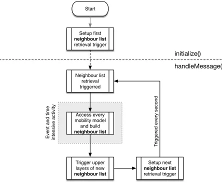
of the physical layer characteristics associated with wireless communications. We do this to avoid the processing time associated with handling events such as channel fading, interference, etc. Instead, we use a simlified model based on unit disc graphs (UDG) implemented through Euclidean and Chebyshev distances, to determine the neighbours in a particular wireless range. Figure1shows the flowchart of activities performed in theinitialize()and thehandleMessage()
stages of theLink Layer model.
Start Setup first neighbour list build trigger First time? Clear used contacts in future contact list
Is lct = st?
Read contact trace, update future contact
list, update lct
Start Setup first neighbour list retrieval trigger Access every mobility model and build neighbour list Trigger upper layers of new neighbour list Setup next neighbour list retrieval trigger Neighbour list retrieval triggerred Contact trace read triggerred Build neighbour list from future contact list Setup first neighbour list retrieval trigger Trigger upper layers of new neighbour list Setup next neighbour list retrieval trigger Neighbour list retrieval triggerred Setup next neighbour list build trigger initialize() handleMessage() initialize() handleMessage()
- last contact time of future contact list - current simulation time lct st yes no yes no Trigger
ed every second
Trigger
ed for every neighbour change
Trigger
ed every second
Event and time intensive activity Event and time intensive activity
removed
Figure 1: Mobility Model based Method: Mobility models accessed to determine neighbours
An initial trigger (self event) is set in theinitialize() to be invoked every second to identify the nodes in the neighbourhood. The handleMessage(), triggered every second, retrieves the coordinates of other nodes, computes and builds a list of neighbours in its wireless range. These are reported to the upper protocol layers.
There are a number of disadvantages of using the current method. Firstly, the high frequency of generating neighbourhood lists per second is a critical time consuming factor. Furthermore, the use of mobility models or traces results in the creation of many events as the nodes have to be moved during the simulation run. This is time consuming. Another major disadvantage of the current method arises when running several simulation with the same mobility scenario. Though the mobility pattern is the same, every simulation run must perform the same procedure over and over again to determine the neighbours.
3.2
Contact Trace based Method
Instead of mobility models, in the contact trace based method, we use contact traces to ob-tain neighbourhood information. Figure 2 shows the flowchart of activities performed in the
initialize() and the handleMessage() stages of the Link Layer model, for the contact trace method.
Start Setup first neighbour list build trigger First time? Clear used contacts in future contact list
Is lct = st?
Read contact trace, update
future contact list, update lct
Start Setup first neighbour list retrieval trigger Access every mobility model and build neighbour list Trigger upper layers of new
neighbour list Setup next neighbour list retrieval trigger Neighbour list retrieval triggerred Contact trace read triggerred Build neighbour list from future contact list Setup first neighbour list retrieval trigger Trigger upper layers of new
neighbour list Setup next neighbour list retrieval trigger Neighbour list retrieval triggerred Setup next neighbour list build trigger initialize() handleMessage() initialize() handleMessage()
- last contact time of future contact list - current simulation time lct st yes no yes no Trigger
ed every second
Trigger
ed for every neighbour change
Trigger
ed every second
Event and time intensive activity Event and time intensive activity
removed
Open contact trace fie
Figure 2: Contact Trace based Method: Contact traces used to determine neighbours
change is present in the neighbourhood. A contact trace contains the timing information and the neighbours with whom the contacts were made.
In the method using mobility models or real traces, the neighbour list was rebuilt every second by getting to know the position coordinates of every node in the network through their mobility models. But, with contact traces, firstly, the trace is read only when thefuture contact list is empty and secondly, the neighbour list is built only if there is a change in the neighbourhood.
Further details of this method is provided in the Section4.
4
Implementation Details
We have implemented the contact trace based method in the model framework we have built to simulate OppNets. Unlike using mobility models or real traces, when using contact traces, there are two distinct activities involved. They are;
1. Generating Contact Traces- The process of generating contact traces from mobility models
2. Using Contact Traces - Once the trace is made, they have to be used in the models that require knowledge of the neighbourhood of a node.
4.1
Generating Contact Traces
The generation of contact traces required the development of a set of models using the INET’s mobility framework. This model set is similar to the current Link Layer models we have developed in the OPS framework to obtain node neighbourhoods.
In this set of models, each node creates a list of nodes in its neighbourhood every second and compares it with the previous second’s list. If some neighbours are missing in the current list which were there in the previous neighbour list, the node considers it as a completed contact and adds it to it’s contact list. In the same way, if some neighbour appears in the current list which was not in the previous list, it is considered as a new contact it started. This process results in contacts being ordered by the end time of every contact. To reduce the complexity of processing the contact traces in large scale simulations such as the ones we perform with the OPS framework [4], we perform the following post processing.
• The trace file, a text file, is made to only hold the start time, the specific neighbour ID
and the contactend time of each contact.
• The contacts are sorted in the ascending order of the contactstart time.
• Every node has it’s own contact trace file containing only it’s own contacts.
Similar to the UDG mechanism adopted in the currentLink Layer models, Euclidean and Chebyshev distances are used to determine the neighbours in a certain wireless range. We use a 30 meter wireless range in this work based on our previous work [11].
4.2
Adapting OPS
Link Layer
The Link Layer of the OPS framework consist of a WirelessInterface model that performs communications with other nodes. In addition to communicating (i.e., delivering packets to other nodes), this model determines the neighbour list, as discussed briefly in the previous section (Section4.1). The calculations done by these models are done every second and upper layers are informed about the neighbours. However, the contact trace based method operates with contact traces and therefore, modifications have to be done on theWirelessInterfacemodel to handle contact traces instead of handling models related to mobility. Figure 2 shown in Section3.2provides a detailed diagram of this algorithm.
TheWirelessInterface model implements theinitialize(), thehandleMessage()and the fin-ish()functions. In theinitialize(), the contact trace file is opened and the initial triggers (i.e., self events) for reading the file are setup. When opening the trace file, automatically, the reading file pointer is positioned to the beginning of the trace file.
ThehandleMessage(), where computations are done to build the neighbour list (accessing model related to mobility of other nodes) is now modified to include new functionality. It is made to read the contact trace into a future contact list and build the neighbour list when changes occur in the neighbourhood. A parameter in theWirelessInterface model determines the number of entries read into thefuture contact list. The contact trace is left open throughout the simulation and therefore, the file pointer of the trace file is always positioned at the next set of contacts to read.
5
Evaluations
The performance evaluation of using contact traces focusses on two phases: Verification phase andBenchmarking phase.
5.1
Verification
The idea behind the verification phase is to prove the results of the simulation is not affected by the modifications done to the original coordinate based systems of mobility. During the verification phase, multiple simulations were run with both methods using a default scenario elaborated in [13] and multiple seeds. Since our scenarios are based on the OPS framework, we verified the metrics ofDelivery Ratio andDelivery Delay. The results were compared to be accurate to the last decimal digit.
5.2
Benchmarking
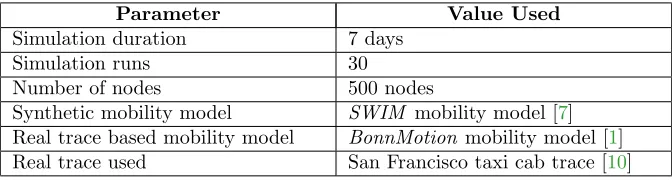
The benchmarking phase focuses on the actual performance comparison of using both methods in large scale simulations. Based on confidence interval computations, 30 simulation runs were done with different seeds used at the upper protocol layers (i.e.,Forwarding Layer of the OPS framework). The simulation used the San Francisco taxi cab trace [10]. The comparison is between the contact trace generated using the San Francisco taxi cab trace and the INET’s
BonnMotionmobility model using the San Francisco taxi cab trace. Table1shows a summary of the simulation parameters.
Parameter Value Used
Simulation duration 7 days
Simulation runs 30
Number of nodes 500 nodes
Synthetic mobility model SWIM mobility model [7] Real trace based mobility model BonnMotion mobility model [1]
Real trace used San Francisco taxi cab trace [10]
Table 1: Summary of simulation parameters
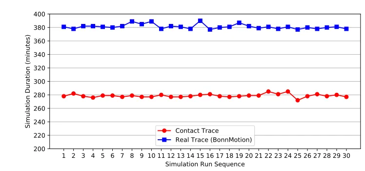
Figure3shows the times (i.e., wall clock time durations) required to complete the simulation runs.
1 2 3 4 5 6 7 8 9 10 11 12 13 14 15 16 17 18 19 20 21 22 23 24 25 26 27 28 29 30 Simulation Run Sequence
200 220 240 260 280 300 320 340 360 380 400
Simulation Duration (minutes) Contact Trace
Real Trace (BonnMotion)
Figure 3: Comparison of simulation times for multiple simulation runs using the San Francisco taxi cab trace with different seeds
The use of traces in simulations require usually some additional processing compared to using synthetic mobility models. The loading of data from files and managing the use of memory where the read items are stored is critical in terms of simulation times. So, our next set of benchmarking evaluations focusses on the comparison of how contact traces perform against real traces and synthetic mobility models.
Method Mean 95% confidence intervals Lower Limit Upper Limit
Real trace 381.2667 380.0096370 382.5237630
Contact trace 278.7667 277.8571164 279.6762836
Table 2: Confidence intervals of simulation durations (all valuesin minutes)
Figure 4 shows the performance comparison between using contact traces and real traces, varying the numbers of nodes. The real trace uses theBonnMotionmobility model with the San Francisco taxi cab trace. The same parameter values listed in Table1are used. The only difference being the varying numbers of nodes, which are increased from 100 to 500 in steps of 100.
When observing the curves, they show that the time required for the simulations to complete has an exponential growth tendency when increasing the number of nodes, especially in the case of theReal Trace. The reason for this behaviour is the complexity of calculations involved in using any coordinate based system during simulations to determine neighbourhoods. The number of calculations needed in one simulation second is increasing with the increasing number of nodes. For example, consider the simulations with 100 nodes and 500 nodes. With 100 nodes, a simulation is required to perform 99 calculations per node per second to find out the neighbourhood. In contrast to that, with 500 nodes, 499 calculation are required per node per second. That increase in the number of calculations results in a higher simulation time.
100 200 300 400 500 Number of Nodes
0 50 100 150 200 250 300 350 400
Simulation Duration (minutes)
8% 10% 15%
28%
25% Contact Trace
Real Trace (BonnMotion)
Figure 4: Comparison of simulation durations with contact traces and coordinate traces when the number of simulated nodes vary
nodes results in an 8% improvement in time and this improvement grows to 28% when running the simulation for 500 nodes. From this, it is clear that the larger the scale of the simulation is, the better the comparative performance with contact traces.
Another of the benchmarking evaluations performed is the comparison of contact traces and synthetic mobility models. The parameters listed in Table1 are used with the SWIM mobility model and the varying number of nodes from 100 to 800. With the synthetic model, we could increase the number of nodes beyond 500 as we were not restricted by the trace size of the San Francisco taxi cab trace. The San Francisco taxi cab trace has mobility patterns of only 536 nodes.
100 200 300 400 500 800
Number of Nodes 0
200 400 600 800 1000 1200
Simulation Duration (minutes)
0% 0% 16% 25%
27%
29% Contact Trace
Synthetic Mobility Model (SWIM)
Figure 5shows that generally, running simulations using contact traces is faster compared to using synthetic mobility models similar to using real traces. However, the graph shows a difference for node sizes of 100 and 200. In this case both methods show almost the same times for completing simulations. But when the number of nodes increases, the advantage of contact method rises from 16% for 300 nodes to 29% for 800 nodes.
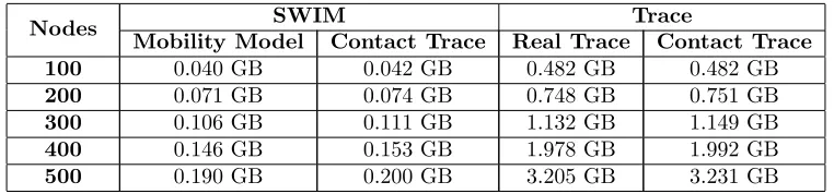
Unlike synthetic mobility models, a key aspect of using traces of any kind is the consumption of memory (RAM) to hold information read from files. Therefore, the efficiency of the algorithm used to load new entries and remove used entries play a critical role, especially when the simulation scale increases.
Nodes SWIM Trace
Mobility Model Contact Trace Real Trace Contact Trace
100 0.040 GB 0.042 GB 0.482 GB 0.482 GB
200 0.071 GB 0.074 GB 0.748 GB 0.751 GB
300 0.106 GB 0.111 GB 1.132 GB 1.149 GB
400 0.146 GB 0.153 GB 1.978 GB 1.992 GB
500 0.190 GB 0.200 GB 3.205 GB 3.231 GB
Table 3: Peak memory usage statistics of simulations
Table3shows the peak memory usage of the previously discussed methods. The simulations use the same parameters listed in Table1but with varying nodes.
The results show that using any kind of trace (real trace or contact trace) requires a higher memory usage than a synthetic model because of the reasons mentioned before (i.e., storage of trace entries). But in all the cases, contact trace based method consumes the highest compared to all methods. But the percentage of increase is very marginal as seen from the listed values. For the simulation speed advantage that contact traces have (as shown in previous results), we consider this to be a minor disadvantage.
6
Summary and Conclusions
Simulation speedup is a critical necessity when the scale of simulations increase. In this work, we investigate the use of contact traces instead of coordinate based systems of mobility (real traces or synthetic mobility models) required to know about the neighbours of a node.
We discuss the algorithms we developed to generate and use contact traces, and finally, compared the performance with real traces and synthetic mobility models. The results show that the contact trace method is significantly faster than the coordinate based systems of mobility when running several simulations. The improvement is around 25% for running 30 simulations with a real trace.
Even running one simulation is faster with the contact trace based method for higher num-bers of nodes in spite of the additional step required before simulations (i.e., generating the contact trace). Reusing contact traces in multiple simulations further improves the timing advantage.
When the nodes are increased, the time improvement of the contact trace based method becomes much more significant compared to the coordinate based systems of mobility. This shows that contact trace based method is more suitable for running large scale simulations.
Though the performance of contact based traces is better compared to other methods, we think that there are still areas that could be further improved. As seen from the results, memory usage is disadvantaged towards the contact trace based method. An improvement would be firstly, to provide a user configurable parameter to decide the maximum number of entries loaded from a contact trace file. A better way would be an automatically decided limit using factors such as the number of entries in the trace file and the simulation duration.
Currently, we use the mechanism where a single trace file is held per node. Though this method is efficient in terms of processing files, it is cumbersome in terms of managing files when there are many nodes. A way forward would be to have all traces in a single file and introduce additional information in this file for file pointers to operate efficiently.
We intend to make these improvements in our next iteration of the code. The contact trace generation code and the code of the WirelessInterface model of OPS where the con-tact trace handling algorithm is implemented is available at https://github.com/ComNets-Bremen/ContactTraceBasedMobility.git.
References
[1] Nils Aschenbruck, Raphael Ernst, Elmar Gerhards-Padilla, and Matthias Schwamborn.
Bonnmo-tion - a mobility scenario generaBonnmo-tion and analysis tool. InSIMUTools 2010, Torremolinos, Malaga,
Spain, 15-19 March 2010.
[2] Tracy Camp, Jeff Boleng, and Vanessa Davies. A survey of mobility models for ad hoc network research. volume 2, pages 483–502. Wiley Online Library, 2002.
[3] A. Chaintreau, P. Hui, J. Crowcroft, C. Diot, R. Gass, and J. Scott. Impact of human mobility
on the design of opportunistic forwarding algorithms. InIEEE Infocom, 2006.
[4] Jens Dede, Anna F¨orster, Ernando Hern´andez-Orallo, Jorge Herrera-Tapia, Koojana Kuladinithi,
Vishnupriya Kuppusamy, Pietro Manzoni, Anas bin Muslim, Asanga Udugama, and Zeynep
Vatan-das. Simulating opportunistic networks: Survey and future directions. IEEE Communications
Surveys Tutorials, 20(2):1547–1573, 2018.
[5] O. R. Helgason and K. V. J´onsson. Opportunistic networking in omnet++. InSIMUTools, March
2008.
[6] Cisco Inc. Cisco visual networking index: Forecast and trends, 2017–2022 white paper. 27 February 2019.
[7] Alessandro Mei and Julinda Stefa. SWIM: A simple model to generate small mobile worlds.CoRR,
abs/0809.2730, Apr. 2008.
[8] Levente M´esz´aros, Andras Varga, and Michael Kirche. Inet framework. In Antonio Virdis and
Michael Kirsche, editors, Recent Advances in Network Simulation: The OMNeT++ Environment and its Ecosystem, EAI/Springer Innovations in Communication and Computing, pages pp. 55 – 106, June 2019.
[9] A.-K. Pietilainen and C. Diot. Experimenting with real-life opportunistic communications using
windows mobile devices. InCoNEXT, December 2007.
[10] Michal Piorkowski, Natasa Sarafijanovic-Djukic, and Matthias Grossglauser. CRAWDAD dataset
epfl/mobility (v. 2009-02-24). Downloaded fromhttps://crawdad.org/epfl/mobility/20090224,
February 2009.
[11] Liu Sang, Vishnupriya Kuppusamy, Anna F¨orster, Asanga Udugama, and Ju Liu. Validating
Diste-fano, and Francesco Longo, editors,Ad-hoc, Mobile, and Wireless Networks, pages 239–252, Cham, 2017. Springer International Publishing.
[12] Asanga Udugama, Jens Dede, Vishnupriya Kuppusamy, and Anna F¨orster. Simulating
opportunis-tic networks with omnet++. InAntonio Virdis and Michael Kirsche, editors, Recent Advances in
Network Simulation: The OMNeT++ Environment and its Ecosystem, EAI/Springer Innovations in Communication and Computing, pages pp. 425 – 449, June 2019.
[13] Asanga Udugama, Jens Dede, Vishnupriya Kuppusamy, Anna F¨orster, Koojana Kuladinithi,
An-dreas Timm-Giel, and Zeynep Vatandas. My smartphone tattles: Considering popularity of
mes-sages in opportunistic data dissemination. InMDPI Future Internet Journal, Special Issue on