DTMF BASED HOME AUTOMATION SYSTEM USING
MICROCONTROLLER WITH PORTABLE POWER
SUPPLY
*Mrs. Ashwini Sawant, **Mr. Sanjay Mirchandani, ***Santoshi Saravanan, ****Shreeparna Sarkar
*Assistant Professor, Electronics and Telecommunication, Vivekanand Education Society Institute of Technology
Chembur, Mumbai, India
**Assistant Professor, Electronics and Telecommunication, Vivekanand Education Society Institute of Technology
Chembur, Mumbai, India
***B.E. Student, Electronics and Telecommunication, Vivekanand Education Society Institute of Technology
Chembur, Mumbai, India
****B.E. Student, Electronics and Telecommunication, Vivekanand Education Society Institute of Technology
Chembur, Mumbai, India
ABSTRACT
Traditional electronic home appliances are controlled using switches. Technological advancements have resulted in more simple and user-friendly developments. This resulted in massive growth in cellular mobile communication technology with mobile phones from a device used for wireless communications to a portable terminal used for networking. Such integrated mobiles introduce a wide variety of applications to explore. This paper introduces a method for using the DTMF tone which is generated by the mobile phone buttons to control the electronic appliances at home. It is possible to control a particular system and acquire information about it from anywhere.
Keywords: DTMF, transmitter, receiver, mobile networks, portable, automation
INTRODUCTION
Many methods available for controlling remote devices require special hardware devices and software which reduces their ease of use. The use of wireless technologies like Bluetooth, GPRS, ZigBee require use of dedicated hardware thereby making their implementation time consuming and costly. This paper makes use of DTMF principle along with prevailing mobile handsets at the receiver end. [3]
working condition within the coverage area of the service provider. Users can control the appliances at home by sending DTMF tone to the other mobile terminal at home. [2]
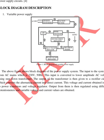
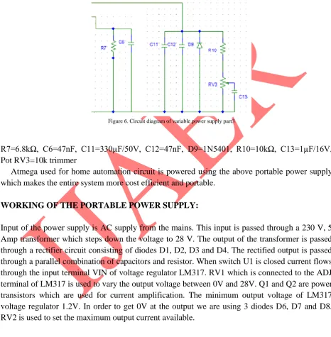
This paper also presents the design and working of a variable output power supply from AC power supply which is used to give input to the home automation system. The main advantage of this power supply circuit is that it provides almost 2 to 3 time higher current than the normal power supply circuits. [4]
BLOCK DIAGRAM DESCRIPTION
1. Variable power supply
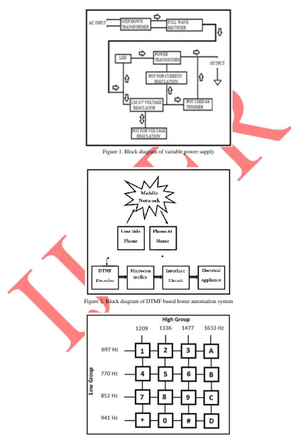
Figure 1. Block diagram of variable power supply
2. Home automation system
Figure 2. Block diagram of DTMF based home automation system
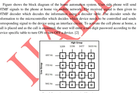
Figure shows the block diagram of the home automation system. User side phone will send DTMF signals to the phone at home via mobile network. The received signal is then given to DTMF decoder which decodes the information using a decoder table. The decoder sends the information to the microcontroller which decides which device needs to be controlled and sends corresponding signal to the device using an interface circuit. To activate the cell phone at home, a call is placed and as the call is answered, the user will enter a two digit password according to the device specific table to turn ON or turn OFF a device. [2]
Figure 3. Frequencies generated on pressing different keys
CIRCUIT DIAGRAM AND WORKING
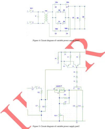
1.1 Variable power supply part 1
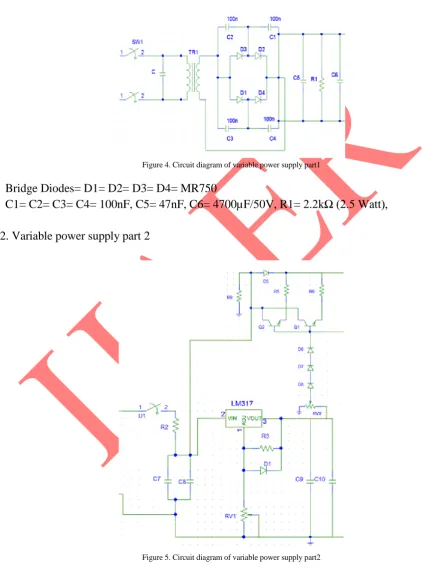
Figure 4. Circuit diagram of variable power supply part1
Bridge Diodes= D1= D2= D3= D4= MR750
C1= C2= C3= C4= 100nF, C5= 47nF, C6= 4700µF/50V, R1= 2.2kΩ (2.5 Watt),
1.2. Variable power supply part 2
R2=47 Ω (0.5 watt), C7=10µF/50v, C8=100nF, R3=240Ω, D1=1n4148, C9=10µF/50V, C10=100nF, D5= D6= D7= D8= IN4001, Q1= Q2= 2N3055, R3= R4= 0.1 Ω (10 watt), R9=8.2kΩ, Pot RV1=5kΩ, Pot RV2=47 ohm or 220 ohm, 1 watt
1.3. Variable power supply part 3
Figure 6. Circuit diagram of variable power supply part3
R7=6.8kΩ, C6=47nF, C11=330µF/50V, C12=47nF, D9=1N5401, R10=10kΩ, C13=1µF/16V, Pot RV3=10k trimmer
Atmega used for home automation circuit is powered using the above portable power supply which makes the entire system more cost efficient and portable.
WORKING OF THE PORTABLE POWER SUPPLY:
2. Home automation interface
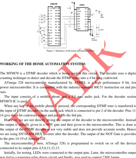
Figure 7. Interfaces of the home automation system
WORKING OF THE HOME AUTOMATION SYSTEM:
The MT8870 is a DTMF decoder which is being used in this circuit. The decoder uses a digital counting technique to detect and decode the DTMF tones into a 4 bit long codeword.
ATmega 328 microcontroller manufactured by ATMEL is a high performance 8 bit, low power microcontroller. It is compatible with the industry-standard 80C51 instruction set and pin-outs.
The input consists of a mobile phone and a 3.5 mm audio jack. For the decoder section MT8870 IC is used.
When any key of the mobile phone is pressed, the corresponding DTMF tone is transferred to the input of DTMF decoder via the audio jack which is connected to pin 2 of the decoder. Pins 11-14 give the 4 bit codeword output and pin 15 is the Std pin.
However, we are not directly giving the output of the decoder to the microcontroller. Instead, the output is initially given to a NOT gate and then given to the microcontroller. This is done as the output of the DTMF decoder is not very stable and does not provide accurate results. Hence, we are using SN74LS04 HEX Inverter after the decoder. The output of the NOT Gate is provided to the pins 14-19 of Atmega 328.
The microcontroller ( here, ATmega 328) is programmed to switch on or off the devices connected to its output pins 4,5,6,11,12,13.
Initially, for testing, LEDs were connected to the output pins. Later, the microcontroller output was fed to a transistor relay driver circuit and finally, was used to control 230V lamps.
TRANSISTOR RELAY DRIVER CIRCUIT:
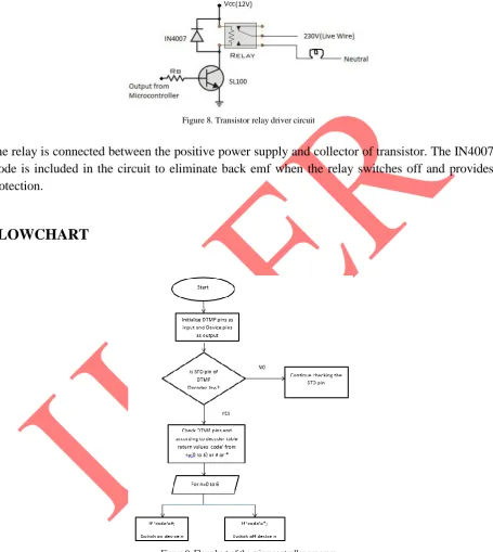
switches. The transistor relay driver circuit is required after the microcontroller as the output voltage is only 5 V and a bulb, tubelight or fan work at 230 V supply.
Figure 8. Transistor relay driver circuit
The relay is connected between the positive power supply and collector of transistor. The IN4007 diode is included in the circuit to eliminate back emf when the relay switches off and provides protection.
FLOWCHART
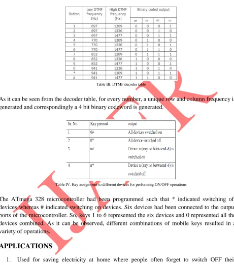
Figure 9. Flowchart of the microcontroller program
RESULT
Table I. Varying output voltage with change in resistance of the power supply circuit
Table II. Varying output current with change in resistance of the power supply circuit
DTMF DECODER TABLE:
Table III. DTMF decoder table
As it can be seen from the decoder table, for every number, a unique row and column frequency is generated and correspondingly a 4 bit binary codeword is generated.
Table IV. Key assignment to different devices for performing ON/OFF operations
The ATmega 328 microcontroller had been programmed such that * indicated switching off devices whereas # indicated switching on devices. Six devices had been connected to the output ports of the microcontroller. So, keys 1 to 6 represented the six devices and 0 represented all the devices combined. As it can be observed, different combinations of mobile keys resulted in a variety of operations.
APPLICATIONS
1. Used for saving electricity at home where people often forget to switch OFF their electronic appliances.
ADVANTAGES
1. There is minimal delay in the system.
2. There is no distance limitation because of the use of mobile network. 3. Cost effective and low power consumption.
4. Any number of devices can be connected for the user to access. 5. Any kind of telephone set or mobile device can be used.
DISADVANTAGES
1. Security issues may arise since any unauthorized person can access the devices at home. 2. Absence of feedback will result in uncertainty of whether the task is performed or not on pressing the corresponding key.
CONCLUSION
This paper presents the working of a home automation system which is based on the DTMF tone generated by pressing the phone keys. When the user at any place pushes a key of his mobile phone, then a corresponding DTMF tone is generated which is transmitted to the mobile phone at home. The decoder table is referred while decoding the DTMF tone received at the receiver depending upon its frequency and corresponding device is either switched ON or Off depending on the command given by the user. The system is portable since it is accompanied by a variable power supply. Also this method uses mobile communication networks for signal transmission and reception thereby enabling the user to have a continuous control of the system in place of his actual presence.
REFERENCES
[1] Adriansyah Andi and Dani Akhmad Wahyu, “Design of Small Smart Home system based on Arduino” in Electrical Power, Electronics, Communications, Controls and Informatics Seminar (EECCIS), 2014 , Issue Date: 27-28 Aug. 2014.
[2] Ladwa Tuljappa M, Ladwa Sanjay M, Kaarthik R Sudharshan, Dhara Alok Ranjan and Dalei Nayan, “Control of remote domestic system using DTMF” in Instrumentation, Communications, Information Technology, and Biomedical Engineering (ICICI-BME), 2009 International Conference on , Issue Date: 23-25 Nov. 2009.
[3] Mulla A., Baviskar J. and Baviskar A., “DTMF Based Automation System with Reduction of Noise Using Goertzel DFT Estimation” in Communication Systems and Network Technologies (CSNT), 2014 Fourth International Conference.
FIGURES AND TABLES
Figure 1. Block diagram of variable power supply
Figure 2. Block diagram of DTMF based home automation system
Figure 4. Circuit diagram of variable power supply part1
Figure 6. Circuit diagram of variable power supply part3
Figure 7. Interfaces of the home automation system
Figure 9. Flowchart of the microcontroller program
Table II. Varying output current with change in resistance of the power supply circuit
Table III. DTMF decoder table