*
Corresponding Authors:
Email Address: [email protected]; Authors have equally contributed to this paper
Improving the Cooling Process of Heavy-Duty Engines through Three Dimensional
Simulation of Fluid Flow in its Coolant Centrifugal Pump
Hesam Moghadasi1 and Sasan Asiaei1* 1
School of Mechanical Engineering, Iran University of Science and Technology
ARTICLE INFO A B S T R A C T
Article history: Received: Accepted: Published:
To extract optimum cooling trends in a heavy duty engine, the 3D flow in a centrifugal pump from the Detroit Diesel company was numerically simulated. For this aim, a computational fluid dynamic model is developed using ANSYS CFX for a wide span of flow rates and a number of shaft angular velocities. The variation of constituting parameters are examined using dimension-less descriptive parameters of flow, head and power coefficients, finally, the efficiency of the pump is examined. In this analysis, ( ) turbulent model is employed which is a combination of two different models for pumps and turbomachines. The characteristic curves of the pump are derived by analyzing the velocity and pressure profile of the coolant (water). This provides a new
conceptual relations from graphs and useful evaluation of the pump
performance at all working conditions. Moreover, engineering and design interpretations from the evolution of the characteristic curves are provided to better engine performance. Numerical results show that prolonged cooling duty cycles of the vehicle should accompany a flow factor of 10%. In addition, the peak of the vehicle’s loading should match the maximum efficiency of the pump that can be increased to 62% by augmentation of flow rate and flow coefficient.
Keywords: Centrifugal Pump Numerical Simulation Characteristic Curve Efficiency
Cooling Process Heavy-Duty Engines
International Journal of Automotive Engineering
Journal Homepage: ijae.iust.ac.ir
2
0
0
8
-9
8
9
9
International Journal of Automotive Engineering (IJAE) 2808
1. Introduction
Pumps are the pivotal part of vehicles cooling system, especially in heavy-duty vehicles. This is due to the limited number of the production, and the fact that these vehicles are designed to operate in severe temperature and load conditions. Therefore, understanding and enhancing the central part of their cooling system, its coolant pump, has essential importance.
Pumps are mechanical devices that transfer fluid from point to point, or from a pressure or energy level to other pressure and energy levels. Centrifugal pumps are more important and common than other pumps due to their simple structural form, low volume to power consumption ratio, and a large variety of their application. A centrifugal pump contains one or few impellers mounted on a shaft and covered by a chamber casing. The fluid axially enters the impeller chamber and the required kinetic energy and pressure is obtained by the rotation of the impeller vanes. When the fluid leaves the impeller, it quickly enters the diffuser where its kinetic energy converts to pressure, accompanied by a drop in speed. To evaluate the performance of the pumps, special curves are prepared called characteristic curves [1]. Among these curves, one of the most important ones are the loci of following parameters against the flow-rate: the head, pump efficiency, and power. These characteristic curves directly demonstrate the performance of pumps and play the major role of all research-works on pumps. To prepare these curves, many experimental and numerical studies have been conducted [2-8], especially examining the flow regime inside the centrifugal pumps [9-12].
Stel et al. [13] studied the fluid flow in the first stage of a two-stage centrifugal pump with a vaned diffuser. They examined the effects of vanes on pressure and flow speed variations in sensitive points of the pump, where significant turbulence occurs. Their Investigation revealed that the flow becomes badly oriented for part-load conditions, where significant levels of turbulence and blade orientation effects are observed in the diffuser. Moreover, in low flow dimensionless coefficient, the classical similarity
rules can be applied. They have also derived a single equation for the pump head to represent the whole operational range of the pump. However, the best efficiency points and the computed hydraulic efficiency of the first stage were overestimated. Bacharoudis et al. [14] conducted a parametric study on the performance of a centrifugal pump’s impeller due to the variation of its outlet blade angles. They performed a 1D approach along with empirical equations for the design of each impeller. For each impeller, the flow pattern and the pressure distribution in the blade passages were calculated and finally, the head-capacity curves are compared and discussed. Their analysis was less computationally intense and straightforward, and the model would yield accurate enough results for small laboratory scale pumps. In 2003, Zhou et al. [15] performed a numerical simulation on the internal flow in various types of centrifugal pumps, showing a good agreement between experimental data and computational results for the twisted-blade pumps. Nonetheless, for the straight-blade pump, the results were different from experimental data due to their lower efficiency and use of the standard model. Shojaeefard et al. [16] studied the viscous fluid flow in a centrifugal pump to determine the head variation in term of discharge with changes in
pump geometry. They found that the
performance can be enhanced by assigning 30° as the output angle of the impeller and 21 mm as the width of the flow path. Alemi et al. [17] considered the impact of volute geometrical changes on the head, efficiency, and radial force of a low specific-speed centrifugal pump. They performed a three-dimensional simulation on the fluid flow by focusing on off-design conditions. They considered the constant velocity and the constant angular momentum volute design methods, revealing that the constant velocity method demonstrates a more satisfactory performance. Moreover, it was concluded that a circular cross-section volute with radial diffusers generates higher heads and efficiencies. The circular volute geometry generates lower radial forces at higher flow-rates in comparison to rectangular cross-section volutes. Mihalić et al. [18] evaluated the characteristic improvements due to an axillary vortex rotor, mounted at the
International Journal of Automotive Engineering (IJAE) 2809 back side of the centrifugal rotor. The
improvements were due to the creation of coherent structures of eddies and turbulence in the peripheral area of the vortex rotor, examined both experimentally and using computational analysis. The study provides evidence for an additional energy, from vortex rotor, that significantly augments the pump head while enhancing the pump stability, at the same time.
In the present study, almost all the aforementioned techniques for better evaluation of the centrifugal pumps were employed, including: numerical measurement of relevant parameters that describe the performance of pump, its physical model, flow visualization derived from the numerical simulation (for interpretation of trends), and analysis of the flow structure at sensitive points to ascertain simulation accuracy. This was all done to gain insights from the best operating condition of the pump, under prolonged steady state, and severe load and hot environmental conditions, and to provide operational suggestions.
To extract the cooling trends of the engine, the centrifugal coolant pump (Detroit Diesel pump) of the vehicle was modelled by ANSYS CFX. In the analysis, ( ) turbulent model is employed and characteristic curves were derived to evaluate the pump performance. The process for determination of 3D flow field is detailed step by step, from defining the relations and equations that govern the problem and the centrifugal pump geometry, mesh generation and its size independence study, and analysis of the results. To discretize the governing equations, the finite volume method with CFX was used. Important flow parameters (velocity and pressure) were predicted in the sensitive points of the pump. Then, the values of the head, efficiency, and power coefficients and pump efficiency was derived and interpreted for the steady stated and extreme working condition of the vehicle. Results suggest that the best steady state cooling cycles of the vehicle are achieved in a flow factor of 10%. Moreover, the peak of the vehicle’s loading is better to accompany the maximum efficiency of the pump (62%) by augmentation of flow rate and flow coefficient.
2. Governing Equations
A turbulent incompressible field is considered for solving the governing equations, due to the incompressibility of fluid and the high-velocity field that is present. The continuity and momentum equations, along with the turbulence model [19] are solved with the following notation, respectively:
(1)
( ̅̅̅̅̅)
̅
( ̅̅̅ ̅̅̅̅̅) ́ ́
(2)
where, and ̅̅̅ are defined as follow:
[ ⃗⃗ ⃗ ⃗⃗ ( ⃗⃗ )]
(3)
̅̅̅ ( ̅ ̅) (4)
In rotational speed , the flow discharge coefficient can be defined by Eq. 5 [21], where stands for the volumetric discharge rate
( ):
(5)
The head and power coefficients can be defined by Eq. 6 and Eq. 7:
(6)
(7)
where the parameter, the required power to run the pump, is defined as follows:
(8)
stands for the required torque from the input shaft. The pump efficiency is calculated by Eq. 9:
International Journal of Automotive Engineering (IJAE) 2810
(9)
3. Flow Turbulence Model
SST turbulence model can apply both
and turbulence models in all regions. In
regions that are very close to the walls, the turbulence model was used and for regions far from the walls, the k-ε turbulence model was adopted. This model firstly improves the turbulence of energy production term in the kinetic energy transfer equation. Research on
two and turbulence models
show that SST and models both accurately predict the flow field close to the walls. Nonetheless, those are much more accurate that the model.Therefore, in the present study, turbulence model was used, which is a combination of two different efficient models, and suitable for pumps and turbomachines [19, 20].
4. Modeling Methodology
The simulated pump completely matches the dimensions and operational properties of the pump loaded in the vehicle with the following specifications (Fig. 1): inlet and outlet diameters are 60 mm, the outer radius of the impeller is 101.31 mm, and water flows inside the properties listed in Table 1. This pump has two inlets and one outlet, and one of the inlets is closed during operation. Depending on the thermal and efficiency demands, a mounted thermostat shuts the first inlet down and loads the second. The impeller is formed with 4 vanes and an angle of 20° (Fig. 3). In its modelling step, it was decomposed into four parts: the lower body, the upper body, impeller, and the upper cover. The operational pump and its models are presented in Fig. 1-6.
Figure 1: The vehicle’s coolant pump
Figure 2: View from the pump’s upper cover
Figure 3: View of the pump’s impeller
The modelling was completed in CATIA, a powerful multi-physics software in the field of design and simulation. In Figs. 4 to 6, the view of the modelled pump in CATIA software is presented.
Figure 4: The upper view of the modeled pump
Outlet
Pressure (outlet)
Pressure (Outlet)
60 mm
Inlet
International Journal of Automotive Engineering (IJAE) 2811
Figure 5: The side view of the modeled pump
Figure 6: The view of the impeller and modeled pump along with the mounted drive
4.1 Meshing
After modeling, the simulation was performed by applying boundary and initial conditions, and accurate meshing. All stages of meshing and numerical simulation were performed by the ANSYS CFX software. Due to the complexity of the impeller and chambers, an unorganized mesh with triangular elements was used, and in the boundaries, a regular and organized mesh was generated. The quality of elements in the constructed mesh was examined to ascertain a proper aspect ratio and avoid sharp edges (angles). The overall view of the generated mesh is presented in Fig. 7.
Figure 7: An overall view of the networked geometry
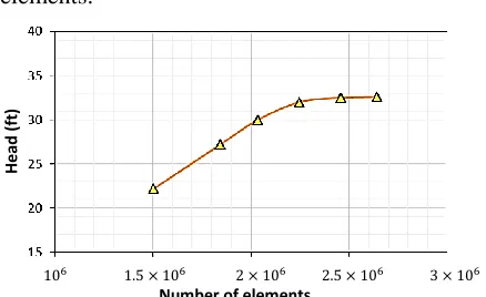
4.2 Mesh Size Independency
The meshing coarseness should be
appropriate, to avoid excessive simulation times for too fine meshes and inaccurate results for coarse meshes. To find an appropriate meshing state, a single-phase flow simulation was repeated, performing a continuous refinement of the mesh. The output discharge rate and pressure were continuously monitored, until the finer mesh entails less than 5% of deviation from the
precedent coarser mesh, reaching 2246779 elements.
Figure 8: Mesh independency study
4.3 Boundary Conditions
An atmospheric pressure was considered at the inlet (zero reference pressure), and the outlet was considered to discharge the fluid far away from the geometrical disturbances, called flow-rate boundary condition. Unless stated otherwise, a rotational speed of 1450 rpm and discharge values in the range of 850 to 2000 Lit/h were considered. The impeller blades and walls were following the non-slip condition, and the roughness effects were ignored [4]. The
turbulence model and a
convergence criterion of 10-5 was used in the simulations. To discretize the governing equations, the finite volume approach was executed by CFX, which is a vertex based Reynolds-averaged Navier–Stokes (or RANS) solver. The continuity and linear momentum equations use pressure and velocity as solved variables, and their discretized version are always coupled for the linear solver. The truncation error tolerance was 10-5. The parameters under study were monitored for the residual error till the parameter become stable. Moreover, running priority was set as standard.
Table 1 summarizes the corresponding fluid properties.
Table 1: Properties of fluid used in the analysis [19]
Value Parameter
H
e
ad
(ft
)
6 5 6 6 5 6 3 6 Number of elements
International Journal of Automotive Engineering (IJAE) 2812
5
Due to the matching of the pump geometry and its simulated model, and well-reasoned assumptions listed above, simulated discharge flow rates had less than 8% of difference with the pump discharge rates at the nominal angular velocity of 1450 rpm.
5. Results
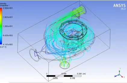
The final aim of modelling a centrifugal pump is obtaining its characteristic curves. These curves are used to gain insights into the best-operating conditions, possibly increasing its load or improving its working condition. To obtain these curves, the response of the pump in different discharge rates is evaluated. Therefore, in each discharge, the centrifugal pump was numerically simulated and pressure and velocity contours were obtained in different areas. As expected, the results confirmed that due to the applied work from the impeller to the fluid, the pressure and velocity of the fluid are increased in the impeller from inner diameters towards the outside. Eventually, in the volute chamber, a portion of the velocity is converted to pressure (Fig. 9).
Figure 9 shows the pump geometry in ANSYS CFX software along with velocity contours. Simulations reveal that sensitive points of extreme velocity and pressure are located in the outer diameters of the impeller vanes and close to the diffuser for all working shaft velocities and demanded heads.
Figure 9: The geometry of considered pump in software and velocity contour resulting from the
simulation
After obtaining pressure and velocity distributions in different velocity and discharge rates, the effect of non-dimensional parameters was evaluated. The curve of the head in terms of discharge rate is shown in Fig. 10.
Figure 10: the head coefficient curve in term of discharge coefficient per angular velocity variations
Figure 11 shows the variation of power coefficient in terms of flow coefficient per various shaft consumption powers.
Figure 11: The curve of power factor in term of discharge coefficient per consumption power shaft
variations
The curve of power factor via the flow coefficient is presented in Fig. 12.
Figure 12: the curve of power factor in terms of discharge coefficient per angular velocity variations
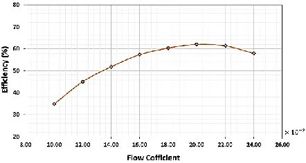
In the final stage, the changes in pump efficiency are evaluated in Fig. 13.
International Journal of Automotive Engineering (IJAE) 2813
Figure 13: the efficiency curve in terms of discharge coefficient (t 1450 rpm)
Considering the important role of the cooling system in engine performance, it can be mentioned that proper adjustment of pump power consumption and maximum efficiency play an important role in improving engine performance. The aim of the present study was to improve the cooling process of the engine. According to the evaluated parameters it can be found that the simulated pump has a fairly good condition for this issue.
6. Discussions
Characteristic curves of Fig. 10 show that an increase in the flow coefficient, due to an increase of flow rate, results in a decrease in the head coefficient, or decrease in the overall head. The results were acquired for different angular velocities. It is shown that in a constant flow rate, head increase requires augmentation of input shaft velocity. Moreover, in a constant head, to increase the discharge rate one should increase the input shaft angular velocity. The most important fact is that around a flow coefficient of 0.1, the head becomes invariant resembling a local extremum. Accordingly, this nearly invariant, maximum head condition is the most suitable working point for the pump for the vehicle in the normal, but prolonged loading condition. The maximum head ensures a complete cooling cycle for all the engine parts receiving the coolant. Due to Eq. 5, this flow condition occurs when the discharge rate stays at a minimum (numerator), provided that the impeller’s diameter is a constant and shaft velocity stays on its nominally low end for prolonged pump life cycle. Thus, for steady state operation of the heavy-duty vehicle, it is
recommended to operate the pump such that the flow coefficient becomes 10%.
Figure 11 reveals that in a constant power (input shaft torque), an increase in flow coefficient or augmentation of discharge rate requires an increase in power coefficient. This can be accomplished by a decrease in input velocity (Eq. 6), which is not always practical. In a constant flow coefficient, an increase of power factor mandates an increase in shaft power consumption, which is not necessarily recommended. Nonetheless, for a constant input shaft power, which is easy to maintain in a vehicle, maximum enhancement rates in power coefficients can be achieved at low flow factors of around 10%. On the other hand, the power coefficient curves reach a plateau at higher flow factors around 22%, where improvements are hard to achieve without an increase in power consumption. This finding confirms the previous recommendation from Fig. 10 for maintaining a lower end flow factor.
Figure 12 demonstrates that in a constant shaft velocity, an increase in flow coefficient (or discharge rate augmentation) results in an increase in power factor or power consumption (Eq. 5 and 7). However, all curves tend to a plateau in higher discharge rates at flow coefficients around 20%, where there is a little need for augmentation of power consumption to increase the discharge rate. Accordingly, for higher demands of coolant circulation rates that unveils in extreme vehicle loading conditions (steep obstacles or hills), it is recommended to run the pump in the higher end of flow coefficients for a better efficiency. In a constant discharge rate, by increasing the angular velocity, the power factor, or demanded power, is also increased. For all power coefficients, an increase of flow coefficient (or discharge rate) requires a decrease in the angular velocity, also verifiable from Eq. 5 and 7. In a constant shaft velocity and higher flow coefficients (20% and above), increase of flow coefficient, or discharge rate augmentation, decreases the power coefficient or the required input power. In other words, the vehicle’s cooling pump efficiency is increased in higher flow factors.
International Journal of Automotive Engineering (IJAE) 2814 From Fig. 13 it is observed that at a nominal
shaft angular velocity, by increasing the flow coefficient, efficiency increases till a flow factor of around 0.02 and after this point, the efficiency fades. Confirmed by the previous findings, the total efficiency of this coolant pump can be increased up to 62% by employing the pump in the higher end of flow coefficient.
7. Conclusions
To achieve the best cooling process in a heavy-duty vehicle, a 3D simulation of fluid flow in a coolant pump was conducted in this study. The velocity and pressure fields were determined to plot the pump’s characteristic curves. For this aim, the computational fluid dynamics analysis in the ANSYS CFX software was performed for a wide range of volumetric flows and a number of rotational speeds. The evolution of dimensionless parameters of discharge coefficients, head and power consumption were investigated. The results showed that an increase in flow rate caused a decrease in head coefficient. In contrast, increasing the discharge coefficient and the power consumption of the shaft leads to an increase in the power factor. It should be noted that in the constant steady state, with increasing angular velocity, the head and power factor also increases. Simulation results revealed for steady state prolonged operation of the vehicle, it is recommended to recruit the pump in a flow coefficient of 10%. Moreover, increasing the volume flow rate, which leads to an increase in the discharge coefficient, increases the total efficiency of the pump to 62%, suitable for maximum vehicle load and thus the cooling duty of the pump.
8.
Nomenclature
m/s2 Gravitational acceleration m/s Velocity component m Coordinate system Pa Pressure Pa Stress Tensor ̅̅̅ N/m3 Body force m impeller head N/m Torque Flow coefficient Power factor W Shaft power consumption
m3/s Volumetric flow rate (discharge rate)
m Radius impeller r kg/m3 Density ρ Pa.s Dynamic viscosity rpm Rotational speed Ω
The coefficient of the impeller head
Pump efficiency
m Radius of impeller
r
Declaration of Conflicting Interests
The author(s) declared no potential conflicts of interest with respect to the research, authorship, and/or publication of this article.
Acknowledgements
The authors would like to acknowledge the support of the ministry of science, research and technology for their financial and software support for this research.
References
[1] A.R. Azimian, R. Motamedi., Simulation of centrifugal pump characteristic using numerical methods, 9th Conference of Fluid Dynamics (2004), Shiraz, Iran.
[2] H. W. Iversen, R. E. Rolling, J. J. Carlson, Volute pressure distribution, radial force on the impeller, and volute mixing losses of a radial flow centrifugal pump, Engineering for Power, Vol.82, No.2, (1960), pp.136-143.
[3] J. W. Daily, R. E. Nece, Chamber dimension effects on induced flow and frictional resistance of enclosed rotating disks. Journal of basic engineering, Vol.82, No.1, (1960), pp.217-230
[4] J. F. Gulich, Effect of Reynolds number and surface roughness on the efficiency of
centrifugal pumps, Journal of fluids
engineering, VOL.125, No.4, (2003), pp.670-679.
[5] S. M. Miner, R. J. Beaudoin, R. D. Flack, Laser velocimeter measurements in a centrifugal
flow pump, Journal of
Turbomachinery, Vol.111, NO.3, (1989), pp.205-212.
International Journal of Automotive Engineering (IJAE) 2815 [6] M. M. Rai, N. K. Madavan, Multi-airfoil
Navier–Stokes simulations of turbine
rotor-stator interaction, Journal of
Turbomachinery, Vol.112, No.3, (1990), pp.377-384.
[7] N. Pedersen, P. S. Larsen, C. B. Jacobsen, Flow in a centrifugal pump impeller at design and off-design conditions—part I: particle image
velocimetry (PIV) and laser Doppler
velocimetry (LDV) measurements. Journal of Fluids Engineering, Vol.125, No.1, (2003), pp.61-72.
[8] M. Vaezi, A. Kumar, The flow of wheat straw suspensions in an open-impeller
centrifugal pump. Biomass and
Bioenergy, Vol.69, (2014), pp.106-123.
[9] S. Derakhshan, A. Nourbakhsh, Theoretical, numerical and experimental investigation of
centrifugal pumps in reverse
operation. Experimental Thermal and Fluid Science, Vol.32, No.8, (2008), pp.1620-1627.
[10] J. Lu, J. Ding, J. Yang, X. Yang, Steady dynamical behaviors of novel viscous pump with groove under the rotor, International Journal of Heat and Mass Transfer, Vol.73, (2014), pp.170-176.
[11] N. Moazami, K. Fukamachi, M. Kobayashi, N. G. Smedira, K. J. Hoercher, A. Massiello, R. C. Starling, Axial and centrifugal continuous-flow rotary pumps: a translation from pump mechanics to clinical practice. The Journal of Heart and Lung Transplantation, Vol.32, No.1, (2013), pp.1-11.
[12] A. M. Georgescu, S. C. Georgescu, C. I. Cosoiu, L. Hasegan, A. Anton, D. M. Bucur, EPANET simulation of control methods for centrifugal pumps operating under variable system demand. Procedia Engineering, Vol.119, (2015), pp.1012-1019.
[13] H. Stel, G. D. L. Amaral, C. O. R. Negrao, S. Chiva, V. Estevam, R. E. M. Morales, Numerical analysis of the fluid flow in the first stage of a two-stage centrifugal pump with a
vaned diffuser. Journal of Fluids
Engineering, Vol.135, No.7, (2013), pp.071104.
[14] E. C. Bacharoudis, A. E. Filios, M. D. Mentzos, D. P. Margaris, Parametric study of a centrifugal pump impeller by varying the outlet blade angle. Open Mechanical Engineering Journal, Vol.2, No.5, (2008), pp.75-83.
[15] W. Zhou, Z. Zhao, T. S. Lee, S. H. Winoto, Investigation of flow through centrifugal pump
impellers using computational fluid
dynamics. International Journal of Rotating Machinery, Vol.9, No.1, (2003), pp.49-61.
[16] M. H. Shojaeefard, M. Tahani, M. B. Ehghaghi, M. A. Fallahian, M. Beglari, Numerical study of the effects of some geometric characteristics of a centrifugal pump impeller that pumps a viscous fluid. Computers & Fluids, Vol.60, (2012), pp.61-70.
[17] H. Alemi, S. A. Nourbakhsh, M. Raisee, A. F. Najafi, Effects of volute curvature on performance of a low specific-speed centrifugal
pump at design and off-design
conditions. Journal of Turbomachinery, Vol.137, No.4, (2015), pp.041009.
[18] T. Mihalić, Z. Guzović, A. Predin, Performances and flow analysis in the centrifugal vortex pump, Journal of fluids engineering, Vol.135, No.1, (2013), pp.011107.
[19] M. Zoljanahi, S. Zirak, Numerical simulation of fluid flow in a centrifugal pump at the design point and outside the design. Scientific Journal of Mechanical Engineering, Vol.16, No.2, (2004), pp.98-88.
[20] S. M. El-Behery, M. H. Hamed, A comparative study of turbulence models
International Journal of Automotive Engineering (IJAE) 2816 performance for separating flow in a planar
asymmetric diffuser. Computers &
Fluids, Vol.44, No.1, (2011), pp.248-257.
[21] B. Jafarzadeh, A. Hajari, M. M. Alishahi, M. H. Akbari, The flow simulation of a
low-specific-speed high-speed centrifugal
pump. Applied Mathematical
Modelling, Vol.35, No.1, (2011), pp.242-249.