Copyright © 2014 IJECCE, All right reserved
Implementation and Analysis of a GSM-Based Security
System with Emergency Control
C.O. Ohaneme, K.A. Akpado, E.N. Ifeagwu, C.O. Ezeagwu
Abstract –The dangers posed on expensive and valuable home properties, industrial resources and human life due to lack of effective security system, call for immediate response in the interest of ensuring that these hazards are averted. With regards to this, this paper aims at providing “A Global System for Mobile Communication (GSM)-based security system with emergency control” capable of monitoring, detecting and reporting specific environmental conditions such as fire outbreak and intrusion in our homes, offices and industries once either condition is met. The system in response to fire incident automatically alerts the fire service agents and the user’s mobile phone to intimate them of the situation. The system as well, triggers an emergency alarm in response to intruder detection in restricted areas and remotely informs the owner of the house, away from home, the security agents and fire fighting experts about the intrusion via a GSM platform, in remote places thereby helping in reducing the rampant cases of vandalization which has plagued many nations. The system implementation is achieved using C-language programming software. The result of the implementation shows that a remote user can conveniently detect and control the anomalies that may occur while being away from home or work place.
Keywords – Emergency Control System, Microcontroller, GSM, C-Language, Security System.
I. I
NTRODUCTIONSecurity is a degree of protection against danger, damage, loss and criminal activity. In other words, security as a system involves all the processes that detect threat from unauthorized sources and initiate action that will prevent hostile acts. Security could be passive or active. A passive security system detects, deter or delay intrusion while active security system detects and responds to intrusion. A good security system is one that poses risk to an attacker to even an attempted intrusion.
Global system for mobile communication (GSM) has impacted our lives in diverse ways. Apart from the basic voice communication, it has other ways of rendering services like its application in security system. For an area where GSM services are available, a security system may incorporate a GSM capability for instant communication.
A security device can be deployed to a field station to monitor an event and alert an administrator when a breach is detected. Such communication is envisioned to take place over a long distance apart and as such GSM is used. Since GSM affords us the opportunity to communicate instantly and also supports mobile communications in real-time, GSM based security system has a measure of reliability. An administrator at one end can issue an instruction over the GSM platform to a field device if an intrusion is detected.
In addition to intrusion detection, fire outbreak can be detected and an automated call be made to fire control
servicemen and an administrator. It is worthy to note that there is a problem such as when the GSM service provider goes out of service. It is still possible to break a security system when all the possible instances of breach have not been considered. Hence there can be no perfect security.
Fig.1. Block diagram of the GSM based security system Fig.1 shows a block diagram of the system. This system is meant to secure a building against fire and burglar incident. A temperature sensor measures the temperature of a strategic location in a building and sends its value to a microprocessor based control. A smoke sensor is added as a way of augmenting the temperature sensor. The control keeps track of the values of the two sensors and whenever the two gives outputs that suggest an outbreak of fire, the control initiates action to keep the situation under control by activating the water pumping unit (pumping machine) that dispenses water to quench fire in the affected fire prone areas. Both sensors must detect fire before the control will conclude an outbreak of fire in the building. First thing the control does when fire is detected is to place an emergency call to the fire servicemen and inform them about the situation. Secondly, it activates the electric motors that pump water from the water reservoir situated within the area to quench the fire. Besides incorporating the pumping unit in the system, alerting the fire fighting experts is still important because the quantity of stored water within the area may not be adequate. In order to ensure that necessary control is effected, this back-up effort is provided to compliment the already installed equipment. A pre-recorded distress voice message will be played by the control once the fire service office picks the call. The voice message will along other information, contain an address of the building for quick response by the fire servicemen. The control will finally seek the attention of the house owner by calling him and informing him about the fire incident.
calls the house owner. A pre-recorded voice message will be played to the house owner to inform him about the intruder. The voice message will tell the owner that an intruder is being detected. Emergency control as incorporated in this work, in addition to calling the house owner, also controls the system by triggering a loud sounding alarm to alert the control authority or to ward off the intruder.
II. R
EVIEW OFR
ELATEDW
ORKSO
NS
ECURITYS
YSTEMA
NDC
ONTROLThis work tends to provide an efficient security management system that is capable of detecting and controlling the fire outbreaks and intruders around homes, offices and industries from remote places via GSM modem (i.e., wirelessly). Generally, wireless communication is the broadcast of electromagnetic waves through free space; that is, without using a physical conductor. Thus, these signals are available to anyone who has a device capable of receiving them [1]. The system is also supported by the mobile capability of the receiver. The goal of mobility is the ability to communicate while moving. Mobile communications technology must be able to allow roaming - the ability to provide service to mobile phone users while outside their home system [2]. Communication systems using the GSM mobile hand phones are made possible by the use of the cellular system. The cellular system allows many users to share limited number of frequency channels available in a region. Although the amount of spectrum (i.e., the number of frequency channels) available could not accommodate all the users if each user were assigned its own unique channel, a cellular system lets frequency channels to be reused in the same area by dividing the entire region into many smaller cells [3]. Hence the areas should be covered by cellular base station which receive and transmit the detected signals to the mobile receiver at various locations. Because cell phones and base stations use low-power transmitters, it is therefore evident that efficient cellular coverage is required for effective management of the entire security system. Otherwise the system will not be effective.
However, several works have been done by other authors on system security and control in recent times. The authors used various means of achieving their aims of providing efficient security system in their various homes by adopting efficient control measures to counter insecurities.
Imagine being able to control all the electrical appliances in a house from virtually any place in the world, GSM home automation may seem like an idea of the future; however there are many possibilities of using it currently [4], [5]. The technology works by allowing communication between a receiver in the house and a mobile phone elsewhere. That receiver can then be signalled to “On” or “Off” appliances in the house based on command from the mobile phone. Through the use of micro-controller, any electrical or electronic device such as a lighting bulb or television can be controlled from a
distance. Mobile Home Automation (MHA) can be applied for convenience and security need. It is also very beneficial. For example, someone who has left home for work in the morning and during the day he realizes that the temperature has gone too high, can remotely turn on the air conditioner in the house as he heads back home. Mobile Home Automation can be used for critical applications. For example smoke and heat sensors can be deployed at homes to detect and report all their readings collected and sent through GSM to a remote user. Of special interest is the capability of the GSM network to be used for data computing. Most people think of voice calls when they think of cellular phones. But because GSM is digital, one can connect a GSM-enabled phone to a laptop computer and send or receive e-mail, faxes, browse the Internet, securely access your computer/intranet, and use other digital data features including Short Messaging Service. Thus this can be used as security control at homes and offices from remote places.
In terms of house Security System, it is important that the system is deployed to the house to protect the house and prevent it from all forms of attack [6]. Security systems are essential in every residential house since there are many forms of security threats round the house. The most basic security system is a simple electric circuit built into an entry way. In such a system, a sensor detects the act of intrusion. -- opening a door. You can also build this sort of system into a window. If an intruder pushes a window open, the sensor detects it and the buzzer is activated. Another simple burglar alarm uses a small button as the switch. The button is embedded in the door frame, so closing the door opens the switch by pushing the button in. When somebody opens the door, the button is released thereby switching on the circuit and sounding the alarm.
Since intruders do not attack from any defined location, it therefore calls for the deployment of motion sensors for detecting the presence of intruders. There are many different ways to create a motion sensor. It is common to have a beam of light crossing the room near the door, and a photo-sensor on the other side of the room. When someone breaks the beam, the photo-sensor detects the change in the intensity of light and rings a bell. Many grocery stores have automatic door openers that use a very simple form of beam detector to detect when someone passes near the door. The box above the door sends out a burst of microwave radio energy and waits for the reflected energy to bounce back. When a person moves into the field of microwave energy, it changes the amount of reflected energy or the time it takes for the reflection to arrive, and the box opens the door. Since these devices use radar, they often set off radar detectors [7]. The same thing can be done with ultrasonic sound waves, bouncing them off a target and waiting for the echo.
All of these are active sensors. They inject energy (light, microwaves or sound) into the environment in order to detect a change of some sort.
Copyright © 2014 IJECCE, All right reserved infrared detectors (PIR) or gyro-electric sensors. In order
to make a sensor that can detect a human being, you need to make the sensor sensitive to the temperature of a human body and also by human shadow. Humans, having a skin temperature of about 93 degrees Fahrenheit, radiate infrared energy with a wavelength between 9 and 10 micrometers [7]. Therefore, the sensors are typically sensitive in the range of 8 to 12 micrometers.
The devices themselves are simple electronic components unlike a photo-sensor. The infrared light emits electrons off a substrate, and these electrons can be detected and amplified into a signal [8].
It has probably been noticed that infrared light is sensitive to motion, but not to a person who is standing still. That’s because the electronics packageattached to the sensor adapts to fairly rapid change in the amount of infrared energy across it, it then means that when a person walks across the sensor, the amount of infrared energy in the field of view changes rapidly and is easily detected.
Besides, microcontroller automation could be used in various homes, offices and industries to provide security as exemplified by [9]. A microcontroller is also sometimes called a computer on one chip [9]. This is because it has all the basic features of a computer. It has a microprocessor, a RAM, a ROM, and input and output ports. Microcontrollers are programmable chips, which mean that they operate by written programs. To use a microcontroller in automation, it needs to be properly biased so as to operate properly. Afterwards an appropriate control program could be written for the controller using its instruction set in assembly or using a high level like C-language. The control program should be constructed from the desired control algorithm. The microcontroller control signals from its input/output ports are interfaced with the correct electronic circuits to be able to effect the desired automation. The resulting system if well designed should be able to carry out the desired automation. Sometimes it is inevitable to automate because of some risk factor. Certain industrial process would have been difficult to carry out with humans. Nuclear reactor is another system that uses automation for safety reasons. Security systems invariably require automation to carry out counter action against an intruder which might be risky for someone considering the fact that an intruder might be armed. Apart from alerting a house owner on security situation in the house, automated security system can take actions like switch a flood light around the compound, sound a very loud alarm in the house, trigger a fire fighting equipment and deny access to the building through electronically controlled entrances. These are made possible by the presence of system transducers/controllers such as smoke sensor, shadow sensor e.t.c.
A smoke sensor is an electronic unit that senses smoke and gives output based on the presence of smoke. The Smoke sensor unit houses the smoke sensor and its complementary circuit. The smoke sensor is designed with Light Emitting Diode (LED) and Light Dependent Resistor (LDR) arrangement. They face each other that when thick smoke is present, it tends to cover the LED light rays and prevents it from reaching the LDR. This will
make the LDR internal resistance to increase thereby making an output voltage to be HIGH. Hence smoke is detected. However when there is no smoke to cover the LED and prevents its light rays from reaching the LDR, then the internal resistance of the LDR decreases and the output voltage becomes LOW. The smoke sensor has an output that interfaces seamlessly to the microcontroller. It gives HIGH output when smoke is detected, otherwise it gives LOW.
In order to detect smoke/fire and the presence of an intruder, some sensor units are required to accomplish that. The Temperature/smoke sensor unit involves a temperature sensor together with its accompanying circuit. It uses LM35 digital temperature sensor. The output of the temperature sensor is interfaced to microcontroller through Analogue to Digital interface. The temperature and smoke sensors together confirm incidence of fire outbreak. The microcontroller needs alert signals from both sensors to make a conclusion.
Also an intruder is detected using an intruder detector unit made of an infrared based detector which is placed at strategic positions around the surroundings and also across passageways/corridors/gangways that a potential intruder may use. When an intruder passes across the infrared transmitter-receiver signal breaking their communication then an intruder is detected at that condition. It interfaces to the microcontroller to give output of High when intruder is detected or Low when there is no detection.
The system further incorporates an alarm unit which is made up of a buzzer and an interface circuitry to the microcontroller as a means of communicating to the users of an impending danger. The buzzer is attached to the system to give an audible alarm when an intruder is detected.
Besides the most distinguishing feature of this work is its ability to communicate with the inhabitants from remote place, i.e., someone who must have been away from home. This is achieved by using a phone modem. The Phone Modem unit provides communication interface capability to the system [10]. Through the GSM medium the system can make call to the Fire Service controllers and the user whenever fire is detected. When the call is received by the Fire Service, a recorded alert message is played to tell the call receiver the location of the fire incidence [11].
III. S
YSTEMD
ESIGNS
PECIFICATIONS ANDA
NALYSISSystem design is the process of obtaining the architecture, component values, modules and interfaces for a system under development.
System specification is the set of documentation that describes the required behaviour of a system. The documentation typically describes what is to be expected from the system by the user as well as features of the system for all conditions of the inputs. Different Characteristic of the entire system is also captured.
A functional specification does not define the inner workings of the proposed system. It does not include the specification on how the system function will be implemented. Instead, it focuses on what various agents using the system might observe while interacting with the system.
A typical functional specification might state the following:
When the user clicks the ‘OK’ button, the dialog is closed and the focus is returned to the main window in the state it was before this dialog is displayed. Such requirement describes an interaction between the user and the software system .When the user provides input to the system by clicking the ‘OK’ button,the program responds by closing the dialog window containing the ‘OK’ button. The entire work has various subsystem units which work in tandem with one another to provide efficient services. The hardware sub-system is about all the physical electronic components of the system. All the electronics components that make up the system are known as the hardware subsystem.
The software sub-system involves the software program written in Embedded C which runs in the hardware. The system functional specification can easily be altered by modification of the software.
A. Hardware Subsystem
The hardware subsystem design involves the design of the following hardware sections which are the power supply, the input interface, the control and the output interface.
Input Devices
Three input devices are considered in this work. They are LM35 temperature sensor, smoke sensor and infrared sensor. The Lm35DZ is a temperature sensor which is used to sense heat rise in the building. It is precision integrated-circuit temperature sensor, whose output voltage is linearly proportional to the Celsius (Centigrade) temperature. It has a sensitivity range of 00C to 1000C. A rise in temperature above 500C is abnormal for a residential or office building. The reading of the LM35DZ is fed to the microcontroller through analogue-to-digital converter. The output of LM35DZ is analogue in nature. To be able to feed it to the microcontroller, it has to be converted to its digital equivalent.
Control Unit
The control section is typically made up of the AT89C52 microcontroller and the components are required to set up the chip. Here, not much design
calculation is needed since the standard component values required to set up the microcontroller and its specifications has been provided by the manufacturers. At89c52 is selected for this work because it has all the features required to implement the design with minimal peripheral components and integrated circuits. Its 32 input/output ports are needful in interfacing all the input and output devices to the microcontroller. Since it has internal RAM and ROM, the problems associated with complex hardwired circuit are taken care of. However, software in form of written program is used to implement the control unit as it is largely dependent on imbedded instructions.
Output Devices
The output devices consist of an arrangement of resistors, transistors and opto-couplers and buzzer. The design involves an electronic system called an opto-couplers which are directly driven by the output bits of the microcontroller. Then, the opto-coupler’s output control the mobile phone buttons. If button on the mobile phone is pressed, it only needs to activate the opto-coupler that interfaces that button.
B. Software Subsystem
The Software used to program the AT89C52 Microcontroller is developed in Embedded C programming language. Software Subsystem program is broken down into two component parts for easier implementation. Under this subsystem, the control algorithm, control flow charts and all other tools that aided in the Software subsystem design are considered. See Fig.2 for a flowchart of the security control system.
Copyright © 2014 IJECCE, All right reserved These form a guide in writing the embedded C language
program. A program can be defined as an orderly sequence of machine instructions that can be obtained by compilation using a high level or low level programming language statement. The written program is burn in microcontroller using EEPROM programmer. Fig. 2 shows control flow chart that depicts the control sequence of the system and the control algorithm of the Pseudo codes thereafter.
The Control Algorithm
Having designed and built the hardware, the AT89C52 chip is as good as nothing if there is no software program to drive the microcontroller. The sequence of operation used to solve a program or achieve a desired output is often called ALGORITHM. It is this sequence of operation that constitutes the action of the microcontroller chip.
A control Algorithm for security system
STARTInitialize all memory locations to their starting values Check for the INTRUDER, TEMPERATURE and SMOKE sensor bits for a high
If INTRUDER bit goes high Then Call the house owner and trigger an alarm
Elseif IF TEMPERATURE AND SMOKE bits both go high Then
Call fire servicemen, call house owner, and display on LCD fire alert message and triggers the electric pumping machine
Elseif
If no sensor is high display on the LCD System Active and go back to check again
End If END
IV. S
YSTEMI
MPLEMENTATIONThe implementation of this work comprises of both hardware and software. Then the hardware system is made up the following unit; the power supply unit, the input unit, the control unit, and the output unit. That is to say, the various units are assembled together to form the composite circuit for the entire system. Each unit is separately tested and verified to be satisfactory before next section is implemented. Then the entire circuits are also engaged in another test before energizing to make sure that every aspect of the system performs effectively.
A. Power Supply Implementation
The Power supply unit supplies 5volts to the circuit to power it, except for the electric motor which uses an alternating source of 220V to operate. The specifications of the power supply unit are as follows:
(1) A 12V, 500mA step down transformer. (2) A units of bridge rectifier at 4A. (3) A filter capacitor of 2200μF by 35V
(4) A 5V voltage regulators at maximum current of 1A. Fig. 3 shows the schematic arrangement of the power supply unit.
Fig.3. The power supply circuit diagram for 5volts
B. Input Unit
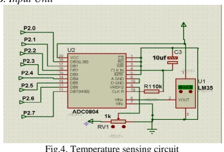
Fig.4. Temperature sensing circuit
The input unit implementations are in three categories, viz: the temperature, the smoke, and the infrared. The LM35DZ voltage supply pin which is the pin 1 is connected to the 5 volts power rail, the ground pin which is the pin 3 is connected to ground rail. The pin 2 that is the sensor output is connected to the ADC0804 input pin 6. The ADC0804 output is connected to the microcontroller port 2. The least and the most bit pin of the ADC0804 is matched with that of the microcontroller.
The smoke sensing section is as shown in Fig. 5. The LED anode pin is connected to the 5 volts supply through a resistor while the cathode is connected to the ground. The LDR first terminal is grounded while the other terminal is connected to inverting pin 4 of the LM339 and one terminal of 5 kilo-ohms resistor. The other terminal of the 5 kilo-ohms resistor is connected to the 5 volts power supply. The output of the op-amp in LM339 is connected to port 3 pin 4 of the AT89C52 microcontroller.
Another input circuit which was implemented is the intruder detector circuit using infrared transmitter/ receiver circuit as shown in the schematic diagram of Fig. 6. The positive terminal of the infrared diode is connected to the 5 volts supply through a 1 kilo- ohms resistor while the other is connected to the ground. The photo-transistor output pin 2 is connected to the inverting input pin 6 of the LM324. The non inverting pin 7 of the LM324 is input to the variable resistor output.
Fig.6. Intruder detector schematic diagram
C. The Control Implementation
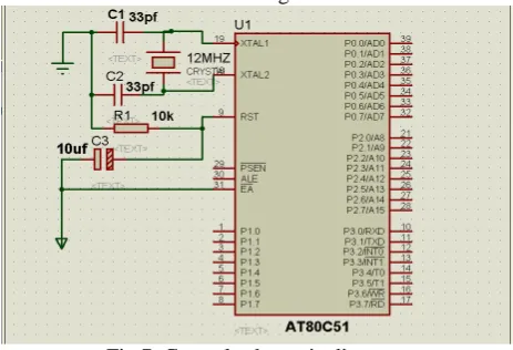
The control section is responsible for carrying out the desired controls via the output bits. It is also responsible for triggering the alarm. The control section consists of an AT89C52 Microcontroller, 11.0592MHz crystal oscillator, resistors, capacitors and a push button. The other components apart from the microcontroller are used to configure the controller for operation. The crystal is connected across pin 18 and 19 of the microcontroller. One terminal of the 33pf capacitor is connected to the pin 18 and 19 of the microcontroller while the other terminal is connected to the ground. The positive terminal of 10 microfarad is connected to the 5volts supply while the ground terminal is connected to the pin 9 of the At89C52. A 10 kilo-Ohms resistor is connected between pin 9 of the AT89C52 and ground. The schematic diagram for the control section is as shown in Fig. 7.
Fig.7. Control schematic diagram
D. The Output Implementation
The output is responsible for carrying out the action defined in the program. The microcontroller executes the program and gives command to the output section to implement. The alarm circuit is one of such output
sections that carry out the command of the microcontroller. The schematic diagram of the sound alarm unit is shown in Fig. 8. One terminal of the buzzer is connected to the Supply voltage (5v) while the other terminal is connected to the collector of the BC547 transistor. The Emitter of the transistor is connected to the ground and the base is connected to port 1 bit 7 through a biasing resistor. A HIGH biases the transistor to switch the alarm ON but a LOW turns it OFF.
Fig.8. Sound alarm schematic diagram
Besides, electric motor is also triggered on to pump water continuously to the affected areas in the event of fire/smoke detection. It is connected to the output port of smoke/fire sensors.
The AT89C51 microcontroller makes a GSM automated call to the house owner and fire servicemen using 4N35, an opto-coupler integrated circuit. The connection of the 4N35 chip is as follows: pin 1 is connected to 5 volts power supply while pin 2 is connected to the collector of the BC547 transistor. The pin 3 and 4 of the 4N35 are connected to the two terminals of the mobile phone button. Four buttons are used, so there are four 4N35 chip for each. The emitter of the BC547 transistor is connected to the ground while the base is connected to port pin of the microcontroller through a biasing resistor. The four port pins used are port 1 bit 3, port 1 bit 4 port 1 bit 5 and port 1 bit 6. The schematic diagram of this section is shown in Fig. 9.
Copyright © 2014 IJECCE, All right reserved and they are connected directed to port 1 of the
microcontroller. The register select, read/write and enable pins are connected to port 3.0, port 3.1 and port 3.2 respectively. The LCD contrast pin, Vee is connected to output of a variable resistor. Fig. 10 shows the schematic diagram for the LCD interface.
Fig.10. LCD interface schematic diagram
Power ON indicator circuit comprise of an LED and a resistor connected in series. The two ends of this circuit are connected across the output of the 5V regulator. Fig. 11 is the schematic diagram of the Power On indicator.
Fig.11. Power ON indicator schematic diagram
E. Software Subsystem Implementation
Implementation of the software design took some definite route to arrive at the required HEX file which is the file that the microcontroller uses. C programming language is used and it took the following sequence of actions;
(1) Port / variable Initialization (2) Coding the main or control function (3) Coding other required functions
(4) Debugging and compiling the source file
(5) Programming the AT89C51 with the HEX file generated by the complier
(6) Running a test of the software program with the hardware.
The software for the system was developed from the algorithm which was realized at design stage. It was written in embedded c programming language a variant of c programming language. The task to be achieved with the software was broken into smaller units for easier and
better structured programming. Each of the smaller units is written as a function. A function called main function is fundamental to every c language program. This main function will call every other function as the program execute sequentially from one line to another.
The other functions that complement the main function were coded. Since these other functions are dedicated to specific duties, they are referenced by the main function as their need arise. Upon execution to the last instruction, these other functions return the program to the main function. The other functions as implemented in this work are for LCD, ADC, LM339, buzzer, GSM phone, electric motor and delay.
When the source file has been fully developed, the compiler is invoked to compile the source file. If the source file has no error of any sort, then the compilation will yield a successful result. On the other hand if the source file has some errors, the compiler will flash error alert messages with indication of the lines that contain those errors. Then the error line is debugged and errors removed. Finally the hex file which will emerge is ready to be downloaded to the microcontroller. The hex file is downloaded to the microcontroller with the help a universal programmer.
V. C
ONCLUSIONIn evaluating the system, it will be logical to say that it yielded the expectation for its design. It monitors for an intruder and triggers an alarm when it detects intrusion. It automatically calls house owner to inform him about an intruder. In the case of fire outbreak, it calls fire servicemen and inform them about the situation. In addition, it calls the house owner to intimate him on the fire incident. It performed creditably according to the design.
However, there is no gain saying the fact that the work is conclusively implemented. There can be useful expansion of its scope to include sophisticated intruder detection system. A network of motion sensors can be deployed for intrusion detection. For places where GSM coverage is not available, there is need for installation/commissioning of GSM base transceiver stations, since the system operation is largely dependent on availability of efficient communication (network) coverage. With the introduction of base transceiver stations, the system would be more resourceful as it can be deployed by industries and homes located at remote places for security. In other words, further research and development is needed to take this project to a higher standard and increased usefulness.
R
EFERENCES[1] Behrouz A. Forouzan,“Data Communications and Networking”, Fourth Edition, Tata McGraw-Hill New Delhi 2007 pp- 467-486. [2] Tom Sheldon, “Encyclopaedia for Networking and
Telecommunication”3rdEdition, McGraw-Hill, 2001
[4] Friedhelm Hillebrand, “GSM and UMTS: The Creation of Global Mobile Communication”,John Wiley, 2002, chapters 10 and 16.
[5] Chatan Sharma, “How Mobile will Change the Way we Spend”, Mobile Future Forward Book Paper, August 2011.
[6] Josh Cark,“What’s the best way to prevent a thief from entering your home” Howstuffworks November 2007, http://www. howstuffworks.com
[7] http: //www. atmel.com, “ATMEL AT89C52, Microcontroller Datasheet”, pg 5-10, copyright 2000-2004
[8] http://www.en.wikipedia.org/wiki/Microcontroller.com “Wikipedia the free encyclopaedia, Microcontroller”, March 2010
[9] Harman T, “Intel microprocessor and Design”, Prentice-Hall Eaglewood Cliffs, New Jersey, 1987, pp 28–33.
[10] Young, Kim, Ramjee, “4G Roadmap and Emerging Communication Technologies”, Artech House 2006, pp 12-13. [11] Toorani M., Beheshti A. A., “Solution to the GSM Security
Weaknesses”, Proceedings of the 2nd IEEE International
Conference on Next Generation Mobile Applications, Services and Technology (NGMAST2008) Cardif UK, September 2008, pp 576-581.
A
UTHOR’
P
ROFILECletus Ogbonna Ohaneme
was born in Nanka in Anambra State of South-East Nigeria. He holds B.Eng. in Electrical/Electronic Engineering, M.Eng. in Electronic and Communication Engineering and Ph.D. in Communication Engineering from Enugu State University of Science and Technology (ESUT) Enugu, Nigeria in 1994, 1998 and 2012 respectively. He is presently a lecturer in the Department of Electronic and Computer Engineering Nnamdi Azikiwe University, Awka Nigeria. Besides, he is a member of several professional bodies including Nigeria Society of Engineers (NSE), Nigerian Institution of Electrical and Electronic Engineers (NIEEE), Council for the Regulation of Engineering in Nigeria (COREN), and International Association of Engineers (IAENG). Also, he has published many articles both local and international journals some of which include: (1) “Analysis and Modeling of Call Droppings in a Well Established Cellular System”.IUP Journal of Science and Technology India, Volume 7 No.4 December 2011, pp 46-59, ISSN: 0973-2268; (2) “Analysis of Interference and Channel Capacity in a CDMA Wireless
Network Using Dynamic Channel Assignment (DCA) Strategy”,
International Journal of Computer Network and Communications (IJCNC), Vol.4 No.5, September 2012, pp 149-163; (3)“Analysis of
Ambient Noise Leveland its Impact on the Capacity of CDMA System”,
International Journal of Innovative Technology and Exploring Engineering (IJITEE), Volume 1, Issue-4 September 2012. ISSN: 2278-3075, pp 72-78. His research interest is on Wireless Communication Networks and Spectrum Management.
E-mail: [email protected] & [email protected]
Kenneth A. Akpado
holds B.Eng. in Electrical/Electronic Engineering from Federal University of Technology Owerri in 1996, Nigeria M.Eng. in Electronic and Communication Engineering and Ph.D. in Communication Engineering both from Nnamdi Azikiwe University Awka, Nigeria in 2004 and 2011 respectively. He is presently a lecturer in the Department of Electronic and Computer Engineering Nnamdi Azikiwe University, Awka Nigeria. Besides, he is a member of several professional bodies including Nigeria Society of Engineers (NSE), Nigerian Institution of Electrical and Electronic Engineers (NIEEE), Council for the Regulation of Engineering in Nigeria (COREN). Also, he has published many articles both local and international journals some of which include: (1)“
Simplifying Industrial Process Control monitoring Using Linked State Machine Approach”, International journal of Electrical and Telecommunication system research, Vol. 4, No. 4, 2011, (2)“Analysis
and Enhancement of a DSR protocol with Self healing Optimizing
Technique”, International Journal of Advances in Science and Technology (IJAST), September, 2011 issues, and (3) “Analysis of Dynamic Source Routing Protocol for Wireless Ad-hoc Networks”, Journal of Engineering and Applied Sciences, Vol. 5, 2009. E-mail: [email protected]
Emmanuel Ncheta Ifeagwu
holds B.Eng. in Electrical/Electronic & Computer Engineering (Electronic and Communication option) from Nnamdi Azikiwe University Awka, Nigeria in 2004; M.Eng. in Electrical/Electronic Engineering (Communication Engineering option) from University of Benin, Benin-City, Nigeria in 2008. He is currently running a PhD programme in Communication Engineering from the department of Electrical/Electronic Engineering of Enugu State University of Science and Technology (ESUT) Enugu, Nigeria. Emmanuel is presently a lecturer in the Department of Electronic and Computer Engineering Nnamdi Azikiwe University, Awka Nigeria. Besides, he is a member of several professional bodies including Nigeria Society of Engineers (NSE). Also, he has published many articles both local and international journals some of which include: (1) “ Performance Analysis for Optimization of CDMA 20001X Cellular Mobile Radio Networks”, International Journal of Scientific and Engineering Research (IJSER) Vol. 3 Issue 3, pp. 1-12, March 2012; (2) “Evaluation of Spectral Efficiency, System Capacity and Interference Effects on CDMA Communication System”, International Journal of Advanced Computer Science and Applications (IJASCA) Vol. 3 Issue 6, pp. 20-25, July 2011, and (3)“Accurate Pathloss Model Prediction for Macro-Cellular Radio
Network”, International Journal of Advances in Science and Technology (IJAST) Vol. 3 No. 4 pp. 53-64, 2011.
E-mail: [email protected]
Christopher Ogwugwuam Ezeagwu
was born in Ezi, Aniocha Local Government Area of Delta State Nigeria. He holds B.Eng. in Electrical/Electronic Engineering and M.Eng. in Electronic and Communication Engineering both from Enugu State University of Science and Technology (ESUT) Enugu, Nigeria in 1986, and 2008 respectively. Currently, he is a PhD student in the department of Electrical/Electronic Engineering, Enugu State University of Science and Technology (ESUT) Enugu, Nigeria. Christopher is presently a lecturer in the Department of Electronic and Computer Engineering Nnamdi Azikiwe University, Awka Nigeria. Besides, he is a member of several professional bodies including, Nigeria Society of Engineers (NSE) , Member Institution of Electrical and Electronic Engineers (IEEE), Fellow Institute of Chartered Administration (ICA) of Nigeria and Council for the Regulation of Engineering in Nigeria (COREN). Also, he has published many articles both local and international journals some of which include:(1) “Suppression of Power Line Interference in ECG using Adaptive Digital Filter”, International Journal of Engineering Science and Technology (IJEST), Vol.3 No. 8, August 2011; (2) “Design, Modelling and Simulation of a Microcontroller Based Temperature Control in a Ventilation System”, International Journal of Advanced Research in Electrical, Electronics and Instrumentation Engineering (IJAREEIE) Vol. 2 Issue 7, July 2013 and (3) “Investigation of the Impacts of Base Station Antenna Height, Tilt and Transmission Power on Network Coverage”, International Journal of Engineering Science Inventions (IJEI) Vol. 2 Issue 7, July 2013.