Reliable Timekeeping for Intermittent Computing
Jasper de Winkel
Delft University of Technology Delft, The Netherlands
Carlo Delle Donne
Delft University of Technology Delft, The Netherlands [email protected]
Kasım Sinan Yıldırım
∗University of Trento Trento, Italy
Przemysław Pawełczak
Delft University of Technology Delft, The Netherlands [email protected]
Josiah Hester
Northwestern University Evanston, IL, USA [email protected]
Abstract
Energy-harvesting devices have enabled Internet of Things applications that were impossible before. One core challenge of batteryless sensors that operate intermittently is reliable timekeeping. State-of-the-art low-power real-time clocks suf-fer from long start-up times (order of seconds) and have low timekeeping granularity (tens of milliseconds at best), often not matching timing requirements of devices that experience numerous power outages per second. Our key insight is that time can be inferred by measuring alternative physical phe-nomena, like the discharge of a simpleRCcircuit, and that timekeeping energy cost and accuracy can be modulated depending on the run-time requirements. We achieve these goals with a multi-tier timekeeping architecture, named Cas-caded Hierarchical Remanence Timekeeper (CHRT), featur-ing an array of differentRCcircuits to be used for dynamic timekeeping requirements. The CHRT and its accompanying software interface are embedded into a fresh batteryless wire-less sensing platform, called Botoks, capable of tracking time across power failures. Low start-up time (max 5 ms), high resolution (up to 1 ms) and run-time reconfigurability are the key features of our timekeeping platform. We developed two time-sensitive batteryless applications to demonstrate the approach: a bicycle analytics tool—where the CHRT is used to track time between revolutions of a bicycle wheel, and wireless communication—where the CHRT enables ra-dio synchronization between two intermittently-powered sensors.
∗Also with Ege University, İzmir, Turkey.
Permission to make digital or hard copies of all or part of this work for personal or classroom use is granted without fee provided that copies are not made or distributed for profit or commercial advantage and that copies bear this notice and the full citation on the first page. Copyrights for components of this work owned by others than the author(s) must be honored. Abstracting with credit is permitted. To copy otherwise, or republish, to post on servers or to redistribute to lists, requires prior specific permission and/or a fee. Request permissions from [email protected]. ASPLOS ’20, March 16–20, 2020, Lausanne, Switzerland
© 2020 Copyright held by the owner/author(s). Publication rights licensed to ACM.
ACM ISBN 978-1-4503-7102-5/20/03. . . $15.00 https://doi.org/10.1145/3373376.3378464
Figure 1.Botoks platform. The front (left) contains radio, antenna, solar panel and MCU. On the back side (right) is the Cascaded Hierarchical Remanence Timekeeper. The board dimensions are 1"×1".
CCS Concepts • Computer systems organization →
Embedded hardware;Embedded software;Sensor net-works; • Hardware→Sensor devices and platforms; Wireless devices;Emerging architectures;
Keywords Energy Harvesting, Timekeeping, Embedded Sensor Networks
ACM Reference Format:
Jasper de Winkel, Carlo Delle Donne, Kasım Sinan Yıldırım, Prze-mysław Pawełczak, and Josiah Hester. 2020. Reliable Timekeeping for Intermittent Computing. InProceedings of the Twenty-Fifth In-ternational Conference on Architectural Support for Programming Languages and Operating Systems (ASPLOS ’20), March 16–20, 2020, Lausanne, Switzerland.ACM, New York, NY, USA, 15 pages. https: //doi.org/10.1145/3373376.3378464
1
Introduction
harvested energy, however, makes computation, communica-tion, and actuation very likely to beintermittent. In this case, power failures become a frequent occurrence. Recovering gracefully and efficiently from those interruptions has been a theme for intermittent computing research [17, 39].
Researchers have addressed theintermittent computing
challenge by designing methods to ensure forward progress and maintain data consistency across repeated power failures. Software-based solutions have tried to mitigate the short-comings of intermittent operation either by instrumenting programs with checkpoints [1, 7, 50], or by rewriting appli-cations using task-based programming models [18, 42, 62]. Hardware and platform approaches have focused on reduc-ing the cost of checkpointreduc-ing [21], managreduc-ing energy more efficiently to reduce power failures and increase event de-tection [7, 15, 16], and getting a rough estimation of time elapsed between power failures [19, 49]. However, despite the amount of progress achieved in the intermittent com-puting domain, reliable infrastructure-less deployment of intermittently-powered sensors remains challenging due to the lack of one fundamental feature,robust timekeeping. The ability to keep track of time undergirds a multitude of com-puting and networking primitives such as synchronization and networking, data collection, and real-time operation. Problem Statement.Having access to an accurate, contin-uous notion of time has always been taken for granted in embedded system development. Timeouts and timestamps constitute the backbone of embedded applications, particu-larly those targeting sensing, communication and actuation. The intermittent operation of ultra-low-energy batteryless devices makes it impossible to track time solely relying on on-chip digital timers, as they are not available during a power outage. Even dedicated ultra-low-power real-time clocks are not a good fit for intermittent operation, as they require very long start-up times1and a high initial energy deposit after each power outage.
Importantly, real-time clocks and other embedded systems timekeeping standards are statically provisioned with en-ergy, usually conservatively to cover the longest possible outage likely to be encountered. The problem with this ap-proach is that the timekeeper’s energy buffer (usually, its internal capacitor) is alwaysover-provisionedto measure the longest expected outage, even if short outages are the com-mon occurrence. This wastes energy maintaining the large energy buffer. This notion of over-provisioned timekeepers is summed up in our key research question:"Why would we provision a timekeeper to last ten hours when we only need to time an outage of a few seconds?"
As of now it is impossible to dynamically set timekeeping granularity, energy cost, and start-up time of an embed-ded timekeeper. Exploiting reconfigurability in software for 1For instance, more than a second for Abracon AB18X5 [45]
ultra-low-power real-time clock.
intermittently-powered runtimes would be aided by a flexi-ble timekeeper. Having power-failure-resilient and adaptive timekeeping would enable new applications, including re-liable intermittently-powered radio communication (since intermittently-powered embedded nodes require methods forsynchronizinglocal clocks to align wake-up times), times-tamped data collection and real-time scheduling.
Contributions.This paper seeks to providehardware and software kernel support to enable continuous timekeepingthat is resilient against repeated power failures incurred by bat-teryless devices operating intermittentlyand adaptive to the dynamic constraints of intermittent computing. The hard-ware layer is inspired by the concept of remanence time-keepers [19, 49] to keep track of time even when the de-vice is depleted of energy. Remanence timekeepers work by discharging a small capacitor over a large resistor dur-ing execution and off-time, and measurdur-ing the voltage once power returns to estimate the time elapsed between two reboots. However, as the measured time increases, the res-olution of the remanence timekeeper decreases (due to the exponential energy decay of an RC circuit), making it diffi-cult to design a timekeeper that hasmillisecond resolution
andmulti-second longevity. Our observation is that cascading multiple of these cheap RC circuits of different sizes together, arranged hierarchically, can result in both high resolution and long timekeeping range, with low energy cost, low cold-boot time, and small area. Thesoftware layerabstracts the remanence timekeepers and makes them ready to use in any existing or future runtime for intermittently-powered sensor nodes. The contributions of this work are as follows:
1. Timekeeping architecture resilient to power failures.We present a timekeeping architecture, denoted as Cas-caded Hierarchical Remanence Timekeeper (CHRT), that enables continuous tracking of time across re-peated power failures. With the CHRT, multiple cas-caded remanence timekeepers (each with different ca-pacitors sizes) enable any software runtime supporting batteryless (and intermittent) operation to select de-sired timekeeping resolution and range.
2. Runtime CHRT support.A kernel software module ac-companies our CHRT architecture to abstract its com-plexity and to expose a simple and effective API to the programmer. The hardware abstraction layer provides accurate millisecond-scale timekeeping information, and minimizes energy consumption of the CHRT based on run-time energy harvesting conditions.
3. Batteryless timekeeping sensor.With the aim to allow developers to experiment with the CHRT and its ker-nel module, we design and build a hardware platform named Botoks2, featuring an energy harvester, an CHRT and an ultra-low-power active radio (see Figure 1) ready
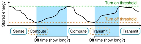
Sense Compute Compute Transmit Transmit
Off time (how long?) Off time (how long?)
Turn off threshold Turn on threshold
Stored energy
Figure 2.Energy-harvesting batteryless sensors operate in-termittently, with execution broken up by power failures of unpredictable duration. These off times are hard to measure with existing timekeepers such as real-time clocks.
to be used to prototype complete timekeeping battery-less applications.
The timekeeping architecture embedded in Botoks is first characterized independently, and then evaluated inside two case-study applications, emphasizing the importance of times-tamps and network synchronization.
2
Motivation
Ultra-tiny Internet of Things (IoT) devices without batter-ies present intriguing possibilitbatter-ies for a more sustainable computational fabric, with application domains previously considered unfeasible becoming more attainable (like micro-satellites [7], deep-tissue micro-implants [41], and massive-scale agriculture via augmented insects [32]).
Intermittent Operation.Batteryless systems are usually powered by ambient energy and operate intermittently [17, 39], as shown in Figure 2. The core of the research in re-cent years was devoted to the design of efficient runtimes ensuring correctness of computation and memory consis-tency despite power failures [6, 21, 42–44, 50, 62]. For embed-ded devices engaging with real-time constraints and sensor data, efficient computation is only one of multiple neces-sary capabilities. Today, building and deploying untethered, batteryless IoT devices is challenging becausetimekeeping re-silient to power failures is imprecise, inaccurate, and statically provisioned. In the absence of an external synchronization signal (e.g., coming from a controlled light source, or from an RF signal generator), accurate timekeeping support for intermittently-powered devices proves crucial.
Timekeeping through Power Failures.Low-power time-keeping solutions of today present challenges for intermit-tent operation: either they are not designed for fast restarting and short execution bursts—like real-time clocks—or they rely on signals coming from external infrastructure or the ambient, like light- or RF-based synchronization architec-tures [20, 60]. Real-time clocks (RTCs) rarely time sub-second intervals, and critically have excessively long cold-boot times (tens of seconds for some low power models if power fails, as in Table 1). This excessive boot time is tolerable for the battery-powered devices RTCs were made for, where power
Start-up time Current
RTC Model Resol. Nominal Worst draw
NXP PCF85263A [53] 10 ms 200 ms 2 s 320 nA Abracon AB18X5 [45] 10 ms 900 ms 21.5 s 55 nA
ST M41T62 [57] 10 ms <1000 ms 1 s 350 nA Maxim DS139X [31] 10 ms <1000 ms N/A 500 nA Table 1. Comparison of selected ultra-low-power RTCs. Note thatallcommercial off-the-shelf RTCs have large start-up times and do not sstart-upport one millisecond resolution.
failures were rare and failure time generally short, while operation time after failure was orders of magnitude longer. RTC developers traded off cold-boot time for lower power operation and smaller footprint. This trade-off, however, is a killer for intermittently-powered devices, where power-down failures are usually longer than operational time. These devices lose power even tens of times per second [50, 59], meaning that an RTC on a intermittently-powered device could still be in a cold-boot state when the energy runs out, wasting energy and losing timekeeping accuracy. In addition to cold-boot problems, on-reboot SPI/I2C config-uration of these devices wastes valuable energy and time. Network-level sources of time, or sensed signals like visible light communication, power line noise [36], or RF carrier are not always viable, as these sources are not guaranteed to be present in a particular deployment and are susceptible to noise or interference.
2.1 Remanence Timekeepers
Remanence timekeeper, introduced in Mayfly [18], was the most promising attempt at intermittency-safe, infrastructure-free local timekeeping. A remanence timekeeper is essen-tially a capacitor discharging through a resistor (RC circuit), whose voltage level is sampled on reboot to get an estimate of the time that has elapsed while the device was powered off. As the voltage decay can be easily modeled and can happen while the MCU is off, the timekeeping accuracy was good enough to enable real-time sensing.
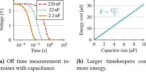
10−4 10−2 100 102
0 1 2
Time [s]
Voltage
[V]
220 nF 22 nF 2.2 nF
(a) Off time measurement in-creases with capacitance.
0 2 4 6 8 10
0 10 20 30
E=CV22
Capacitor size [µF]
Ener
gy
cost
[µJ]
(b) Larger timekeepers cost more energy.
Figure 3.Partial design space for Remanence Timekeepers.
is indistinguishable for a 12-bit analog-to-digital-converter). It becomes arduous to find a configuration that can satisfy different needs of an application, balancing and anticipating all these trade-offs at design time.
Timekeeping Rigidity.Beyond the physical constraints, application behaviors with time-varying timekeeping re-quirements mean that a single remanence timekeeper tuned to aspecific outage lengthis not useful for outages of a differ-ent length. For example, synchronizing radio transmissions needs millisecond-level timekeeping, while a humidity sam-pling task only needs minutes or hours. A single remanence timekeeper sized to time outages measured in milliseconds with high precision cannot give any idea of the passing of time at the minute level. Time accuracy, resolution, and pre-cision needs are application-dependent and dynamic. Static remanence timekeepers are too rigid to be useful.
Cost, Size, Complexity.Despite the large trade-off space, remanence timekeepers offer attractive benefits due to the simplicity of the circuit, allowing for ultra small size and cost. While most RTCs can be upwards of one US dollar even at scale, the discrete components of a remanence timekeeper can be purchased for less than a penny, and even less when built into a modern CMOS process.
3
System Overview
In light of the shortcomings of single remanence timekeep-ers and RTCs, this paper argues for a different approach where multiple remanence timekeepers of increasing capac-itance are chained together. Depleted tiers automatically activate the next smallest tier. For short time intervals the smaller tiers provide higher resolution and consume less energy, while the larger energy-expensive tiers time longer intervals. From this key idea, we explore the complex de-sign space of multi-tier remanence timekeeping with the CHRT, an intermittency-safe timekeeping architecture, and build Botoks, an energy-harvesting device with an on-board CHRT. The benefits of using CHRT are summarized below. Consistent Time Resolution.Compared to single-tier de-signs, the multi-tier timekeeper does not suffer from loss of
Platform Intermitt.-safe
Infrastr.-independent
Time-aware
Hamilton [33] ✗ ✓ ✗
WISP [55] ✓ ✗ ✗
BLISP [22] ✓ ✗ ✗
Capybara [7] ✓ ✓ ✗
Flicker [16] ✓ ✓ ✗
Botoks ✓ ✓ ✓
Table 2.Comparison of selected low-power sensing plat-forms of the past two decades. Botoks, and its timekeeper (CHRT), are resilient to intermittent operation, and do not depend on external infrastructure.
resolution as the discharge curve flattens, meaning that high resolution can still be leveraged after long outages. Reduced Boot Time/Energy.Boot time for the CHRT is bounded only by the size of the capacitor, unlike for RTCs, where the capacitor must be filled, then the RTC must stabi-lize, then the RTC registers must be configured. With nearly-instant boot-up and energy only dedicated to timekeeping, the CHRT enables time tracking through short outages. Lower Energy Consumption.RTCs and single remanence timekeepers are provisioned with a specific amount of energy at design time, tuned to the best guess of the maximum power failure time. A CHRT can be provisioned at run-time so that the smallest tier that can time the likely length of the next outage is used. In this way the device avoids wasting energy on charging up unnecessarily large capacitors for timing short outages.
Overall Goals.Looking at Table 2, compared to existing low-power platforms, Botoks features intermittency-safe, infrastructure-independent timekeeping, effectively enabling time-critical intermittent applications. Botoks embeds an ultra-low-power radio as well, ready to be used in combi-nation with the CHRT for infrastructure-less intermittent networking applications.
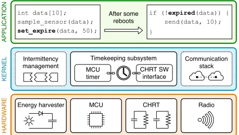
MCU
HARDW
ARE
KERNEL
APPLICA
TION int data[10];
sample_sensor(data);
set_expire(data, 50);
if (!expired(data)) { send(data, 10); }
After some reboots
CHRT
Energy harvester Radio Communication
stack Timekeeping subsystem
Intermittency
management CHRT SW interface MCU
timer
Figure 4.Botoks high-level architecture. The runtime ker-nel keeps track of time using the CHRT. Applications are instrumented with CHRT functions to infer on the elapsed time despite power outages.
in Figure 4 and described in Section 6, which will be used to evaluate our design (refer to Section 7).
In summary, our goals are: (1) enable accurate and consis-tent timekeeping, (2) allow runtime provisioning of CHRT tiers to enable energy savings, and (3) provide software con-structs for easy usage of the timekeeper in any runtime system.
4
CHRT: Hierarchical Timekeeping
The limitations of ultra-low-power timekeepers for battery-less and intermittently-powered systems listed in Section 2 motivate our new timekeeping architecture. The main idea is to combine multiple capacitive timekeepers of different sizes into aCascaded Hierarchical Remanence Timekeeper(CHRT). The varioustiersof the CHRT can be used to minimize cold-boot time and energy consumption, and maximize resolution and timekeeping range at run-time. The tiers are linked to-gether, from smallest to largest, so that a depleted tier can automatically activate the next tier, therefore increasing the total timing range, whilst maintaining the best possible res-olution. For short time intervals, the smaller tiers provide higher resolution and consume less energy. The larger tiers are used to time longer intervals, but have lower resolution and need more charging energy. To be able to use the CHRT, the cascaded tiers have to be pre-charged at each reboot. Our hardware abstraction layer, described in Section 5, can be configured to minimize energy consumption depending on the needs of an application and the expectations of energy availability of the environment, by specifying how many tiers should be pre-charged at each reboot.
4.1 CHRT Circuit
A schematic of the CHRT circuit is shown in Figure 5 (only the first two tiers and the last tier are shown). The stable charging voltage VCHis provided by a ultra low power
regu-lator, not shown in the figure. The switches allow the MCU
to recharge the capacitors and then to let them discharge through the resistor. The comparator is used to trigger the various stages of the cascade, i.e., a CHRT tier is activated when the voltage across the preceding tier drops below the reference of the comparator (VR). The control signal CEN can
be used to bypass the cascaded behavior and use any of the tiers as an independent timekeeper. Using the tiers indepen-dently, programmers can map tiers to particular functions based on the timing granularity required.
4.2 CHRT Range Heuristics
To determine the number of CHRT tiers and their size, time-keeping requirements need to be extracted. These range heuristics can be partially inferred from the application it-self. If data is of no use 10 seconds after it was gathered, then there is little reason to have a timekeeper that can cap-ture periods longer than 10 seconds. Application code for embedded systems is usually full of timing requirements baked into the program. Often these are explicit: many task-based programming models have data timing requirements stored on the edges of the task graph [18]. We also imagine that empirical programming methods could use annotations or assertions to define the timekeeping requirements. Be-yond application information, such requirements could be extracted from predictions about the environment. For par-ticularly energy-sparse environments, larger tiers may be required to sustain through interruptions.
Once the time requirements have been extracted (for ex-ample, expiration time of data, synchronization granularity of communication), one can decide on the number of tiers and their size by examining the total range required, and the granularity. Since each tier can only cover a portion of the final timing range, we can use simple RC calculations to find these ranges.
Tier’s Range.Assume a resolution ofδt is required, using anN-bit ADC, a resistorR and a capacitorC, and during calibration and usage the capacitor is charged atV0(which
is also the maximum value the ADC can measure). We want to find the maximum time interval∆tmaxsuch that, for all
∆tx < ∆tmaxand∆ty = ∆tx+δt ≤ ∆tmax, the difference between the ADC values corresponding to∆txand∆tyis at leastKintegers. Larger values ofKyield better robustness against noise, but reduce the timekeeping range of a capaci-tor. Assume thatVx is the voltage associated to∆tx, andVy
is associated to∆ty(∆tx <∆ty ⇒Vx >Vy). Then, we want
Vx−Vy ≥KV0
2N, (1)
and, by applying the RC circuit discharge model, that is, t =−RCln(V/V0), to (1), we obtain
∆ty ≤RC ln
2N K
exp
δt
RC
VCH
C1
A1
R1
CS1 DS1 VCH
C2
A2
R2
CS2
DS2
CEN
−
+
VR
A1
VCH
CN
AN
RN
CSN DSN CEN
−
+
VR
AN−1
Figure 5.Cascaded Hierarchical Remanence Timekeeper. The left-most stage is activated first, while the subsequent stages are activated in a cascaded manner. VCH: regulated output that charges the timekeepers; CSi: charge signal of tieri; Ai: voltage
sampling point of tieri; DSi: discharge signal of tieri; CEN: cascaded mode enable signal; VR: comparator reference voltage.
Equation (2) can be used to obtain the maximum timing range of an arbitrary tier. A negative value means that the specificRCcircuit cannot be used with a resolutionδt. Number of Tiers.Applications have a variety of accuracy and range requirements. In a critical software section a data sample might expire within a few milliseconds, non-critical data samples within 100 ms and the output might be times-tamped with the accuracy of one second. This requires a range of different tiers to maintain the accuracy restrictions. Given a set of timekeeping requirements, expressed in terms of resolution and maximum time-able interval, (2) can be used multiple times to compute the number of CHRT tiers required and their size. We have implemented this heuristic in a script [10] that suggests a CHRT configuration based on the timing requirements extracted from program code or given by the developer3. However, we note that for many
applications the default configuration used in Botoks is likely to be suitable (see Section 6). This configuration allows for timing outages up to 100 s with a resolution up to 1 ms.
5
CHRT Software Layer
The CHRT architecture presented in Section 4 is comple-mented by a software layer, whose aim is twofold: (1) make the best usage of the available tiers to maximize energy efficiency and timekeeping resolution and range, and (2) ab-stract the complexity of the CHRT to provide a user-friendly API. More specifically, the software layer exposes (1) araw interface, which can be used to directly request the CHRT hardware to charge the tiers and retrieve elapsed time on reboot, and (2) ahigh-level interface, which uses the CHRT in combination with a digital timer to provide higher-level functionalities, like timestamp generation and data expira-tion. Additionally, the software is responsible for a one-time factory circuit calibration that must be performed before using the CHRT, as in the case of RTCs.
3Details on this heuristic are also presented in [9, Section 4.2.1].
5.1 CHRT Hardware Abstraction Layer
The raw CHRT interface is a hardware abstraction layer (HAL) of the underlying timekeeping hardware functional-ity, to be used for low-level control of the CHRT. It is mostly intended as a building block for more advanced timekeep-ing duties to be exposed by the runtime or kernel that has knowledge of the user tasks and operations, but can be used at the application level as well by the user. Upon reboot, the runtime calls a function to retrieve the time elapsed since the previous reboot, and then another function to recharge the tiers. A non-goal of the HAL is to make the CHRT fully invisible to its user (for instance, the recharging procedure has to be explicitly called). The intermittency-management kernel (like InK [62] or Chinchilla [43]) can use the raw API to define its custom timekeeping functions, or just pass the high-level CHRT interface up to the application layer. Elapsed Time Retrieval.Upon reboot,chrt_get_time()
must be called to get the elapsed time of the power failure that was just recovered from. This function returns a 16-bit unsigned integer representing the elapsed time, and a scaling factor. The scaling factor times the elapsed time gives a time value in milliseconds.
Dynamic Tier Recharge.After retrieving elapsed time,
chrt_charge()must be invoked to recharge the CHRT tiers. This function provides a means to specify how many tiers are charged on each reboot, to reduce energy consumption and cold-boot time while still preserving the required time-keeping resolution and range. This function is useful for setting the dynamism of tier recharge to adapt the timekeep-ing energy expended based on application or environmental properties. Programmers and intermittent kernel designers can choose to be eitherconservative oradaptivewith tier recharging.
T0,T1, . . . ,TN−1, chosen as suggested in Section 4.2, and that Ri =timin,timax is the optimal timekeeping range of tierTi,
again, determined as given in Section 4.2. We calltarget tier
Txthe tier whose optimal timekeeping rangeRxcontains the
elapsed time retrieved on reboot. Suppose that the CHRT is configured to only charge one tier, the target tier, on reboot. Then, if tierTxis charged on rebootj, and the timetretrieved on rebootj+1 is not inRx, the target tier to be charged on rebootj+1 would beTx+1(if it exists) in caset ≥txmax, or
Tx−1(if it exists) in caset<tminx . The adaptive method saves
energy since overcharging the timekeeper when the kernel is only timing a short outage is wasteful.
When the reboot frequency is variable the kernel may choose to beconservativein timekeeper provisioning (tier recharging), as retrieved times are more likely to be outside the timekeeping range of the current target tier. For better robustness against variable reboot frequency, the user can request the CHRT to charge more than just the current target tier. Specifically, the two function parametersKLandKRare
used to tell the CHRT software layer to charge all tiers in T
x−KL,Tx+KR, given thatTxis the current target tier. For
instance, ifKL =KR =1, tiersTx−1,Tx andTx+1would be
recharged on reboot, and the discharge would start from tierTx−1, and continue with the larger tiers in a cascaded
fashion. The parametersKL andKR control the trade-off
between timekeeping robustness and energy consumption, as charging more tiers requires more energy. In particular, KRhas a higher impact on energy consumption, due to larger
tiers needing more charging energy.
5.2 CHRT High-Level API
The CHRT HAL described previously exposes the most basic functions to control the CHRT. Thehigh-levelCHRT inter-face enhances raw functionalities to provide higher-level timekeeping tools to be used in real-world batteryless ap-plications for intermittent devices. Fundamentally, this is implemented combining CHRT functionalities with an on-board MCU digital timer to maintain an always-available system time. The system time is incremented at each reboot using the rawchrt_get_time()function. When queried during on-time, the system time is combined with timing information retrieved from the digital timer running in the background. The system time is used to generate timestamps and to set expiration timers for data and functions. Figure 6 demonstrates the usage of this high-level API.
Timestamp Generation.get_timestamp(): a high-level API function, uses the aforementioned system time to gener-ate a timestamp when the application requires it. In particu-lar, the returned timestamp is a 32-bit unsigned integer repre-senting system time in milliseconds. Whenget_timestamp()
is invoked, the value of the MCU timer is added to the CHRT-powered system time to return a fine-grained timing value that can be used to annotate data.
Expiration Timers.The high-level API exposes two more functions to keep track of aging data, and discard it when it is deemed expired. The functionset_expiration()can be used to set an expiration time for some data, or for a complete function/task. The user passes atag(of typevoid
pointer), representing the object (data or function pointer) to be assigned an expiration time, and anexp_time(of type
uint32_t), to set an expiration time in milliseconds. Then, the API functionhas_expired()can be called, passing a
tag, to check at any point if some object has expired. Timekeeping Subsystem.The high-level API can be inte-grated by a kernel runtime to implement a full timekeep-ing subsystem for the application layer to use. The runtime must only implement atimekeeper_init()function to call during initialization, where the system time is updated (us-ingchrt_get_time()) and the CHRT is recharged (with
chrt_charge()).
5.3 CHRT Software Calibration
Ideally, theRC circuit discharge model,t =−RC ln(V/V0),
could be used to estimate the elapsed timet. In actuality, capacitanceCand resistanceRnever match their nominal values, and other parasitic capacitors and resistors are spread through the circuit. To resolve this issue, a software calibra-tion routine, to be performed before CHRT deployment, was implemented, to obtain better precision and accuracy of the timekeeper. During calibration, all the tiers of the CHRT are repeatedly charged and discharged, and their discharging profile is sampled over time to obtain a realistic physical model for each tier. This way, an interpolated version of the RCcircuit discharge model is built and stored in the form of a lookup table. At run-time, the voltage across the target tier is used to look up the table and retrieve the corresponding elapsed time.
6
System Implementation
This section lists and briefly discusses the parameters we used for the implementation of CHRT hardware and soft-ware, and describes in more detail the components of the integrated Botoks demonstration platform. All hardware, software, and tools, as well as documentation for CHRT and Botoks, are open-sourced [10].
6.1 CHRT Platform
The four-tier CHRT was implemented (1) as a system pe-ripheralintegrated into Botoks, built with off-the-shelf SMD components (see Figure 1), (2) as astand-alonedevelopment board, featuring the same components as on Botoks, and (3) as anintegratedversion.
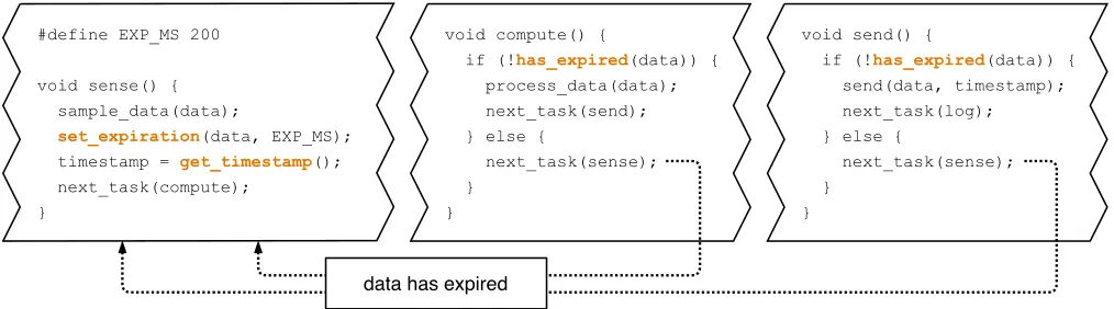
void compute() {
if (!has_expired(data)) {
process_data(data); next_task(send); } else {
next_task(sense); }
}
void send() {
if (!has_expired(data)) {
send(data, timestamp); next_task(log); } else {
next_task(sense); }
} #define EXP_MS 200
void sense() { sample_data(data);
set_expiration(data, EXP_MS);
timestamp = get_timestamp();
next_task(compute); }
data has expired
Figure 6.Example usage of the high-level CHRT API. The program is a typical sensing routine, and the API is used to specify that the elapsed time between sensing and transmission of some data must not exceed 200 ms of absolute time (on and off), as well as to get a timestamp to be sent together with the data.
value of the discharge resistor was fixed at 22 MΩ for all the tiers, as such resistors are cheap (less than a tenth of a USD cent per unit) and guarantee a good balance between long discharge time of the RC circuit and electrical noise. Larger resistors would allow for even wider timekeeping ranges, but the incurred noise would become detrimental to the accuracy and the precision of the CHRT. As for the capacitors, we mixed different sizes to obtain a variety of resolutions and timekeeping ranges, to cover the needs of various applications. Precisely, we chose to cascade four tiers of increasing size: 2 nF, 22 nF, 220 nF and 2200 nF. The best resolution achievable with such configuration is 1 ms, when using the smallest tier, which is guaranteed for capturing time intervals up to 100 ms. The longest time-able interval is 100 s, measurable using the largest tier, for which a resolution of 1 s is guaranteed.
CHRT with SMD Components.We built the CHRT with off-the-shelf components on a custom PCB as a proof of con-cept. Other than the four RC circuits, the CHRT includes other important components. Each capacitor is readable via a trace to an ADC channel on the MCU. Ultra-low-power D-type Flip Flops (SN74AUP2G79 [25]) protect the input sig-nals after the MCU dies. TS3A4751 [27] switches are used to gate power to the capacitors. For the cascaded effect, TLV3691 [26] comparators are set to enable the discharge of a tier when the voltage on the previous tier drops below 0.25 V. The stand-alone CHRT includes jumpers to enable or disable individual tiers.
CHRT Integrated Design.The proof-of-concept PCB is not what we envision will be eventually deployed in the battery-free IoT, an integrated circuit design scales better and is more cost effective in volume. We have also implemented the CHRT in a TSMC 0.18 µm mixed-signal process [58], and simulated the circuit with Cadence Virtuoso [2] in order to extract power consumption estimates of the integrated ver-sion of our architecture. The integrated design is significantly
lower power and ultra tiny, enabling integration alongside batteryless enabled microcontrollers for low cost instead of expensive crystal centered RTCs. We report the power consumption numbers in Section 7.3.
6.2 Botoks Platform
Our batteryless sensor, Botoks, is meant to be used as a com-plete development board to evaluate and experiment with the CHRT, therefore it also includes an ultra-low-power MCU, an energy harvester and an ultra-low-power radio. Specifically, the device is centered on a Texas Instruments ultra-low-power FRAM-enabled MSP430FR5994 microcon-troller [28], with 256 kByte FRAM and 8 kByte SRAM. By default, energy is harvested via the small solar cell on the back of the PCB, and is routed into the 100 µF main storage capacitor. A MIC841 [23] comparator with hysteresis lets the MCU turn on only when sufficient charge is available. The ultra-low-power active radio transceiver is built around the Microsemi ZL70550 [8] chip (as of time of writing, the lowest power 868 MHz radio transceiver available) and a monopole antenna. The complete fabricated device is shown in Figure 1. We expect this platform to enable other researchers and prac-titioners interested in battery-free devices.
6.3 Software
7
Evaluation
To quantify the performance of our system, we first character-ize the behavior of the CHRT in terms of accuracy, precision and power consumption. Then, we evaluate it in the context of two case study applications implemented for Botoks, to demonstrate the usefulness of a time-aware intermittently-powered device. In summary we found that the CHRT is accurate and precise at high resolutions (1 ms) and for long ranges (hundreds of seconds), has two orders of magnitude lower startup time than a RTC, and has an ultra low power consumption, especially in the integrated design.
7.1 Experimental Setup
Botoks and its on-board CHRT were used throughout all the experiments. To evaluate timing performance the platform was connected to a continuously-powered microcontroller (a TI MSP430FR5994) that was used as a simulated intermittent power source, in order to control power-on and power-off times. For the case studies,solar,radio frequencyand mag-netic energy sources were used, as detailed in Section 7.4 and Section 7.5. To sample digital and analog traces, a Saleae Logic Pro 16 logic analyzer [52] was used. Finally, for power consumption measurements the X-NUCLEO-LPM01A ex-pansion board [56] was used.
7.2 Evaluation Methodology
Our timekeeping architecture is benchmarked both on a fine-grained scale and on an application scale. Thefine-grained benchmarkstargets performance metrics such as timekeep-ing accuracy and precision, energy consumption and ini-tialization time. Thecase-study benchmarks (applications)
showcase the performance of the CHRT when used in real-world scenarios.
We build a bike speedometer using CHRT by capturing elapsed time between consecutive events (revolutions of the wheel). For this type of applications, timekeeping ability and accuracy is necessary to provide reliable readings of the bike speed. However, the constraints on accuracy are not as tight as other real time systems.
The second application is a message passing protocol that aligns radio communication of two intermittently-powered devices. In this case, robust timekeeping is a stricter require-ment, since active radio transmission and reception consume a lot of energy, thus it is crucial for networked nodes to know exactly when to turn on their radio to minimize packet loss and energy waste.
7.3 CHRT Microbenchmark
In order to characterize the isolated performance of the CHRT, a Botoks node was powered by a controlled source that was physically cutting power to the node under test at predefined frequencies. All four tiers of the on-board CHRT were tested extensively across various time ranges and at
0 50 100
0 50 100
Real time [ms]
A
verage
measured
time
[ms] Ideal
RT (220 nF) CHRT
(a)Tier 0 (2.2 nF) average mea-sured time.
0 50 100
0 50 100
Real time [s]
A
verage
measured
time
[s] Ideal
RT (220 nF) CHRT
(b)Tier 3 (2200 nF) average mea-sured time.
-2 -1 0 1 2
0 20 40 60 80 100
Error [ms]
Distrib
ution
[%]
(c)Tier 0 (2.2 nF) error.
-2 -1 0 1 2
0 20 40 60 80 100
Error [s]
Distrib
ution
[%]
(d)Tier 3 (2200 nF) error.
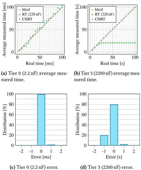
Figure 7.CHRT average measured time (top) and error dis-tribution (bottom) for time measurements in the intervals 1 ms to 100 ms (tier 0, resolution of 1 ms) and 1 s to 100 s (tier 3, resolution of 1 s).
various resolutions. The smallest tier (2.2 nF) was tested in the range 1 ms to 100 ms, with steps equal to its resolution of 1 ms. Similarly, the other three tiers (22 nF, 220 nF and 2200 nF) where tested in the ranges 10 ms to 1000 ms, 100 ms to 10 000 ms and 1 s to 100 s, respectively, with steps equal to each tier’s resolution (10 ms, 100 ms and 1 s, respectively). CHRT Accuracy.Figure 7 presents the accuracy of the small-est tier and the largsmall-est tier of Botoks’s on-board CHRT. Fig-ures 7a and 7b show the average reported time of the two tiers, for their optimal timing ranges, where every data point is the average of 10 measurements. The accuracy of a single-tier remanence timekeeper (of 220 nF) is also presented, to show the need for flexible multi-tier remanence timekeepers. If the designer selects only a single tier a compromise be-tween resolution and timekeeping range is required. Single tiers have poor results for time ranges longer than what the RC circuit can sustain (the single-tier saturates to around 20 s when trying to capture time intervals larger than that), therefore motivating our multi-tier CHRT.
Charge energy(µJ) Start-up
Timekeeper Theoretical Measured time (ms)
CHRT Tier 0 0.00529 0.010† 0.3114 CHRT Tier 1 0.05819 0.110† 0.5053
CHRT Tier 2 0.58190 1.295† 0.913
CHRT Tier 3 5.81900 5.434 3.125 CHRT Total 6.46438 6.636 4.893 Table 3.CHRT dynamic energy consumption, i.e. energy to charge each tier, and charging times. The CHRT has much lower lower start-up time than any state-of-the-art RTC.
two tiers have a maximum absolute error equal to their re-spective resolution, which is the case for the other two tiers as well. The error distribution is well centered on zero, and it is very narrow, demonstrating that the CHRT is accurate and precise at high resolutions (1 ms) and for long ranges (hundreds of seconds). The error distribution of a single-tier remanence timekeeper operating outside its optimal time-keeping range has a much higher standard deviation, which is the reason why it was not plotted at all.
Energy Consumption.The static current consumption of the four-tier CHRT amounts to 0.958 µA for the SMD ver-sion (the one embedded in Botoks), and to 37.335 nA for the integrated version4, when powering the circuit at 2.2 V. We also measured the energy required to charge the tiers at each reboot, as reported in Table 3. In Figure 8 the energy required to measure time is reported over the whole time measurement range. Not only CHRT measures with much higher accuracy than state-of-the-art RTCs, but also the re-quired energy to measure time is comparable orlower, even diregarding configuration time of RTCs.
Initialization Time.Initializing the CHRT boils down to recharging the depleted tiers. The start-up time for each of the tiers embedded in Botoks is reported in Table 3. Even when all the four tiers have to be recharged, the initialization time of the CHRT (≈5 ms) is orders of magnitude smaller than for any available RTC (refer to Table 1).
Chip Area.The estimated footprint of the integrated four-tier CHRT is less than 1 mm2(excluding packaging), proving its suitability for ultra-small embedded systems.
7.4 Application 1: Bicycle Analytics
For the bike speedometer application, Botoks’s energy har-vester was replaced with an off-the-shelf magnetic energy
4 Integrated design: NAND gate,G, consumes 15 pA, comparator,M,
7.43 nA, and the oscillator driving the comparator,S, 15 nA; all values were measured at 1 kHz oscillator frequency. Therefore, forN-tier CHRT the total static current draw is(N−1) × (G+M)+S. Current draw of switches was below 15 nA and therefore removed from the calculation.
10−3 10−2 10−1 100 101 102
10−2
100
102
Measured time [s]
Ener
gy
cost
[µJ]
AB18X5 PCF85263A CHRT
Figure 8. Comparison between CHRT and two RTCs from Table 1 of the total energy required to time a period. The CHRT allows for millisecond timing whilst requiring less or similar energy compared to the lowest power RTC.
0 20 40 60
10 20 30 40
Tier 1 Tier 0
Time [s]
Speed
[km
/
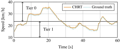
h] CHRT Ground truth
Figure 9. Calculated speed of the bicycle, in km/h, over a period of 60 s. The result obtained with Botoks and its embedded CHRT is compared to the ground truth. As shown, the two smallest tiers of the CHRT are dynamically used through the experiment.
TX RX TX RX
Lux RPS Lux RPS d RPS d RPS
S1 11k 6.6 33k 12.5 RF1 0.6 m 12.5 0.6 m 17.3
S2 26k 9.5 26k 9.6 RF2 0.8 m 12.9 0.8 m 16.4
S3 26k 10.4 11k 5.9 RF3 1 m 11.6 1 m 12.6
Table 4.Description of scenarios described in Figure 10. S1, S2, and S3, refer to using solar as energy source and RF1, RF2, and RF3 refer to radio-frequency energy harvesting. For solar energy harvesting the amount of Lux is measured at the solar panel; for radio-frequency energy harvesting the distance to the transmitter is listed.RPS: reboots per second.
7.5 Application 2: Intermittent Communication The second embedded application uses the CHRT to align transmission and reception schedules of two intermittently-powered wireless Botoks nodes communicating via active radios. We have established a point-to-point link with two nodes powered by solar energy, in one experiment, and radio-frequency energy, in another experiment. The solar energy was generated by two independent light bulbs placed in two closed boxes and collected by Botoks’s solar panel. The radio-frequency energy was provided by a Powercast transmit-ter [4] and harvested by a Powercast receiver [3] connected to Botoks’s power supply (in place of the solar cell).
In the application, the transmitting node would wake up to send one packet of data, using its buffered energy, even-tually incurring a power failure, proceeding then to harvest energy and finally recharge and wake up again. Similarly, the receiving node would wake up and start listening until receiving a packet, or until a power outage. Each of the 20-Byte packets contained preamble, average on time measured with the CHRT, a dummy payload and 16-b CRC, and was sent at a data rate of 200 kb/s.
The baseline for the experiment is a scheme in which the receiver wakes up and turns on its radio as soon as possible, trying to catch a packet sent by the transmitter. This baseline is compared to the case in which a simple CHRT-powered synchronization protocol allows the receiver to align its listening activity to the transmitter5. Specifically,
the receiver uses the average transmission period contained in each packet to alter its listening schedule and align to the transmitter.
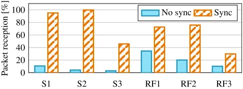
Packet reception rates were measured for the synchro-nized CHRT-powered protocol and for the non-synchrosynchro-nized baseline, for different energy harvesting conditions, as sum-marized in Table 4. Each experiment was run for 10 min. Outcome.We note that this is the first successful case of two intermittently powered devices with active radios pass-ing messages consistently. Figure 10 shows the percentage of received packets (the complementary of lost packets). As 5Details on this network synchronization protocol are also presented in [11].
S1 S2 S3 RF1 RF2 RF3 0
20 40 60 80 100
Pack
et
reception
[%] No sync Sync
Figure 10.Percentage of received packets for a point-to-point link between two Botoks devices, measured in six different energy harvesting conditions described in Table 4. The percentage of packets received using the CHRT-powered synchronization algorithm is compared to the baseline case— with no synchronization. Note that for S3 and RF3 the max-imum packet reception available is 50 %, as the receiving node does not have enough energy to wake up as fast as the transmitting node.
it stands out, our CHRT-based synchronization algorithm yields an improvement over the non-synchronized message passing scheme, resulting in a best-case increase in received packets of 3.77 times for RF and 23.75 times for solar. Inspect-ing the difference between energy sources, solar performed better than RF due to a more consistent wake-up period. The Powercast transmitter transmits a ID every 10ms causing an inconsistent wake-up period.
8
Related Work
Numerous papers in intermittent computing have promised to revolutionize the use of small sensing devices for diversity of application. We place CHRT (and Botoks) in the context of the state of the art.
Batteryless Systems and Sensing.Batteries [48] are an obstacle for long-term embedded sensing. In response to this challenge many battery-less sensing platforms have been proposed in the last decade, which we summarized in Table 2. Botoks does not require central coordination and energy provision point, contrary to e.g. backscatter-based nodes [55] or visible light nodes [20].
Programming Models. Many programming models for intermittenly-powered sensors have been proposed in the past. These can be grouped into checkpoint-based systems— the recent ones being [43, 44], or task-based systems—the recent ones being [42, 62]. None of checkpoint-based pro-gramming models (and very few task-based ones) support time-sensitive data processing. CHRT language constructs enables time-sensitive intermittent computation and sens-ing. CHRT can be integrated into any runtime: task- or checkpoint-based.
Energy Harvesting Sensor Networks. Batteryless sen-sors obtain energy for operation from the ambient. Since energy harvesting patterns arriving at these wireless sensor nodes fluctuate in time and are not easily predictable [38, 54], asynchronous network protocols, such as [46], are used in co-ordinating communication—proposed primarily for battery-powered wireless sensor network. Synchronous network protocols for energy harvesting sensor networks are not practical, simply because a node that experiences a power failure loses its notion of time. Another approach to deal with unpredictable energy harvesting patterns is to keep all nodes in the so-calledenergy neutral operationmode [13, 34], meaning that the consumed energy is always less than the harvested energy (thus power never fails). Our proposal diverges from aforementioned prior works targeted for en-ergy harvesting systems. We propose asynchronized duty-cycling scheme based on batteryless timekeeping, which aligns nodes’ schedulesacross power failures.
Network Time Synchronization.IoT nodes’ clocks are generally sourced by cheap oscillators that are prone to sig-nificant, unpredictable instabilities. Due to these drifts, the local clocks of each node diverges over time. Consequently, it is mandatory to perform periodic time synchronization to ensure that nodes are able to acquire a common notion of time and perform coordinated actions [40]. Naturally, there is a considerable amount of work dedicated to wireless IoT sensors’ time synchronization, such as [35, 37, 61]. The goal of these works is to build a network-wide notion of time. Unfortunately, all these works do not consider very frequent power failures and, in turn, the loss of synchronization state— a common phenomenon among batteryless platforms.
9
Discussion and Future Work
We discuss future directions enabled by Botoks and CHRT. General Application to Embedded Systems.While the CHRT concept is particularly useful for intermittent com-puting, where power failures and energy constraints force designers to rethink timekeeping; CHRT is generally applica-ble to all embedded systems that need timekeeping through power failures and are currently over-provisioned with an RTC. The CHRT offers a modular, lower power, short startup time and energy saving solution over RTCs.
Tool Support for CHRT.Beyond intermittently-powered networking, there is a dearth of tools for intermittent com-puting past EDB [5] and Ekho [14]. As complexity increases of the programming models, hardware, and runtime systems, the tradeoff space grows larger. A tool for exploring the tradeoff space of CHRT would be useful for VLSI design as well as prototyping with off-the-shelf components.
Complex Intermittently-powered Networks.Further ex-ploration is needed on how to expand point-to-point Botoks link into afull-fledged network(if the industry estimates on the proliferation of IoT are to be believed [47]). To achieve this, coordinated compute, voting strategies, etc., must be made robust to intermittent power failures. That said, the techniques shown here could form the basis for some of these protocols. Improvements to our synchronization algo-rithm are required that integrate collisions and increase time accuracy.
Further Evaluation of CHRT.Naturally, we have not ex-plored all possible corner cases of CHRT operation. A crucial measurement considers CHRT use in varying temperatures.
10
Conclusions
We have presented a new battery-less timekeeping mecha-nism enabling reliable batteryless sensing and computation, theCascaded Hierarchical Remanence Timekeeper(CHRT), and presented two application instantiations useful for in-termittent computing: time-critical sensing and intermit-tent communication. The CHRT is based on the idea of a hierarchy of remanence timekeepers which combine accu-racy/resolution, have short cold-start,andallow timing long periods of power failure. Combining the CHRT architecture into one hardware and software platform we presented the design and implementation of Botoks—a new batteryless sensor. With Botoks, and its accompanying CHRT, inter-mittent computing can enter a new phase and explore new applications not possible so far.
Acknowledgments
We thank our anonymous reviewers for their useful com-ments. We also thank Dr. André Mansano and Nowi B.V. for help in measuring the integrated version of the CHRT. This work was in part supported by the National Science Foun-dation under award number CNS-1850496. Any opinions, findings, and conclusions or recommendations expressed in this material are those of the author(s) and do not necessarily reflect the views of the National Science Foundation.
References
[1] Naveed Bhatti and Luca Mottola. HarvOS: Efficient code instrumenta-tion for transiently-powered embedded devices. InProc. IPSN, pages 209–219, Pittsburgh, PA, USA, 2017. ACM/IEEE.
home/tools/custom-ic-analog-rf-design/circuit-design.html, April 2016. Last accessed: Jan. 19, 2020.
[3] Powercast Co. P2110 Powerharvester Evaluation Board. www.powercastco. com/wp-content/uploads/2016/11/p2110-evb1.pdf. Last accessed: Jan. 19, 2020.
[4] Powercast Co. TX91501 Powercaster Transmitter. www.powercastco. com/wp-content/uploads/2016/11/User-Manual-TX-915-01-Rev-A-4.pdf. Last accessed: Jan. 19, 2020.
[5] Alexei Colin, Graham Harvey, Brandon Lucia, and Alanson Sample. An energy-interference-free hardware/software debugger for intermittent energy-harvesting systems. InProc. ASPLOS, pages 577–589, Atlanta, GA, USA, 2016. ACM.
[6] Alexei Colin and Brandon Lucia. Chain: Tasks and channels for reliable intermittent programs. InProc. OOPSLA, pages 514–530, Amsterdam, The Netherlands, Oct. 30 – Nov. 4, 2016. ACM.
[7] Alexei Colin, Emily Ruppel, and Brandon Lucia. A reconfigurable energy storage architecture for energy-harvesting devices. InProc. ASPLOS, pages 767–781, Williamsburg, VA, USA, 2018. ACM. [8] Microsemi Corp. ZL70550 ultra-low-power sub-GHz RF
transceiver. www.microsemi. com/product-directory/sub-ghz-radio-transceivers/3928-zl70550, April 2019. Last accessed: Apr. 10, 2019.
[9] Jasper de Winkel. Keeping track of time on energy harvesting systems. Master’s thesis, Delft University of Technology, Delft, The Netherlands, October 2019.
[10] Delft University of Technology Sustainable Systems Lab. CHRT and Botoks website. https://github.com/tudssl/botoks, August 2019. Last accessed: Jan. 18, 2020.
[11] Carlo Delle Donne. Wake-up alignment for batteryless sensors with zero-energy timekeeping. Master’s thesis, Delft University of Tech-nology, Delft, The Netherlands, November 2018.
[12] Carlo Delle Donne, Kasım Sinan Yıldırım, Amjad Yousef Majid, Josiah Hester, and Przemysław Pawełczak. Backing out of backscatter for intermittent wireless networks. InProc. ENSsys, pages 38–40, Shenzhen, China, 2018. ACM.
[13] Xenofon Fafoutis and Nicola Dragoni. ODMAC: An on-demand MAC protocol for energy harvesting-wireless sensor networks. InProc. PE-WASUN, pages 49–56, Miami, FL, USA, 2011. ACM.
[14] Josiah Hester, Timothy Scott, and Jacob Sorber. Ekho: Realistic and repeatable experimentation for tiny energy-harvesting sensors. In Proc. SenSys, pages 330–331, Memphis, TN, USA, 2014. ACM. [15] Josiah Hester, Lanny Sitanayah, and Jacob Sorber. Tragedy of the
coulombs: Federating energy storage for tiny, intermittently-powered sensors. InProc. SenSys, pages 5–16, Seoul, South Korea, 2015. ACM. [16] Josiah Hester and Jacob Sorber. Flicker: Rapid prototyping for the batteryless internet-of-things. InProc. SenSys, pages 19:1–19:13, Delft, The Netherlands, 2017. ACM.
[17] Josiah Hester and Jacob Sorber. The future of sensing is batteryless, intermittent, and awesome. InProc. SenSys, pages 21:1–21:6, Delft, The Netherlands, 2017. ACM.
[18] Josiah Hester, Kevin Storer, and Jacob Sorber. Timely execution on intermittently powered batteryless sensors. InProc. SenSys, pages 17:1–17:13, Delft, The Netherlands, 2017. ACM.
[19] Josiah Hester, Nicole Tobias, Amir Rahmati, Lanny Sitanayah, Daniel Holcomb, Kevin Fu, Wayne P. Burleson, and Jacob Sorber. Persistent clocks for batteryless sensing devices.ACM Trans. Embed. Comput. Syst., 15(4):77:1–77:28, August 2016.
[20] Kasun Hewage, Ambuj Varshney, Abdalah Hilmia, and Thiemo Voigt. modbulb: A modular light bulb for visible light communication. In Proc. VCLS, pages 13–18, New York City, NY, USA, 2016. ACM. [21] Matthew Hicks. Clank: Architectural support for intermittent
com-putation. InProc. ISCA, pages 228–240, Toronto, ON, Canada, 2017. ACM.
[22] Ivar in ’t Veen, Qingzhi Liu, Przemyslaw Pawełczak, Aaron Parks, and Joshua R. Smith. BLISP: Enhancing backscatter radio with active radio
for computational RFIDs. InProc. RFID, Orlando, FL, USA, 2016. IEEE. [23] Microchip Technology Inc. MIC841 comparator with 1.25% reference and adjustable hysteresis. http://ww1.microchip.com/downloads/en/ DeviceDoc/20005758A.pdf, 2017. Last accessed: Jan. 19, 2020. [24] TI Inc. Msp430 GCC compiler. http://www.ti.
com/tool/MSP430-GCC-OPENSOURCE. Last accessed: Jan. 19, 2020.
[25] TI Inc. SN74AUP2G79 low-power dual positive edge-triggered D-type flip-flop. http://www.ti.com/lit/ds/symlink/sn74aup2g79.pdf, July 2012. Last accessed: Jan. 19, 2020.
[26] TI Inc. TLV3691 0.9-V to 6.5-V nanopower comparator. http:// www.ti.com/lit/ds/symlink/tlv3691.pdf, 2015. Last accessed: Jan. 19, 2020.
[27] TI Inc. TS3A4751 0.9-ωlow-voltage, single-supply,4-channel SPST ana-log switch. http://www.ti.com/lit/ds/symlink/ts3a4751.pdf, March 2015. Last accessed: Apr. 10, 2019.
[28] TI Inc. MSP430FR5994 16 MHz ultra-low-power MCU. www.ti.com/ lit/gpn/msp430fr5994, August 2018. Last accessed: Jan. 19, 2020. [29] TI Inc. MSP MCU programmer and debugger. https://www.ti.com/
lit/ug/slau647m/slau647m.pdf, February 2019. Last accessed: Jan. 19, 2020.
[30] TI Inc. Uniflash standalone flash tool for TI microcontrollers (MCU), sitara processors & SimpleLink devices. https://www.ti.com/tool/ uniflash, November 2019. Last accessed: Jan. 19, 2020.
[31] Maxim Integrated. Low-voltage spi/3-wire RTCs with trickle charger. https://datasheets.maximintegrated. com/en/ds/DS1390-DS1394.pdf, August 2019. Last accessed: Jan. 19, 2020.
[32] Vikram Iyer, Rajalakshmi Nandakumar, Anran Wang, Sawyer B. Fuller, and Shyamnath Gollakota. Living IoT: A flying wireless platform on live insects. InProc. MobiCom, pages 1–15, Los Cabos, Mexico, 2019. ACM.
[33] Hyung-Sin Kim, Michael P. Andersen, Kaifei Chen, Sam Kumar, William J. Zhao, Kevin Ma, and David E. Culler. System architec-ture directions for post-SoC/32-bit networked sensors. InProc. SenSys, pages 264–277, Shenzhen, China, 2018. ACM.
[34] Trong Nhan Le, Alain Pegatoquet, Olivier Berder, and Olivier Sentieys. Energy-efficient power manager and MAC protocol for multi-hop wire-less sensor networks powered by periodic energy harvesting sources. IEEE Sensors J., 15(12):7208–7220, December 2015.
[35] Christoph Lenzen, Philipp Sommer, and Roger Wattenhofer. PulseSync: An efficient and scalable clock synchronization protocol.IEEE/ACM Trans. Netw., 23(3):717–727, June 2015.
[36] Yang Li, Rui Tan, and David K. Y. Yau. Natural timestamping us-ing powerline electromagnetic radiation. InProc. IPSN, pages 55–66, Pittsburgh, PA, USA, 2017. ACM/IEEE.
[37] Roman Lim, Balz Maag, and Lothar Thiele. Time-of-flight aware time synchronization for wireless embedded systems. InProc. EWSN, pages 149–158. ACM, 2016.
[38] Xiao Lu, Ping Wang, Dusit Niyato, Dong In Kim, and Zhu Han. Wire-less networks with RF energy harvesting: A contemporary survey. IEEE Commun. Surveys Tuts., 17(2):757–789, 2015.
[39] Brandon Lucia, Vignesh Balaji, Alexei Colin, Kiwan Maeng, and Emily Ruppel. Intermittent computing: Challenges and opportunities. In Proc. SNAPL, pages 8:1–8:14, Alisomar, CA, USA, 2017.
[40] Junchao Ma, Wei Lou, Yanwei Wu, Xiang-Yang Li, and Guihai Chen. Energy efficient TDMA sleep scheduling in wireless sensor networks. InProc. INFOCOM, pages 630–638, Rio de Janeiro, Brazil, 2009. IEEE. [41] Yunfei Ma, Zhihong Luo, Christoph Steiger, Giovanni Traverso, and Fadel Adib. Enabling deep-tissue networking for miniature medical devices. InProc. SIGCOMM, pages 417–431, Budapest, Hungary, 2018. ACM.
[43] Kiwan Maeng and Brandon Lucia. Adaptive dynamic checkpointing for safe efficient intermittent computing. InProc. OSDI, Carlsbad, CA, USA, October 8–10, 2018. USENIX.
[44] Kiwan Maeng and Brandon Lucia. Supporting peripherals in intermit-tent systems with just-in-time checkpoints. InProc. PLDI, Phoenix, AZ, USA, June 22–26, 2019. ACM.
[45] Ambiq Micro. AM18xx family ultra-low power RTCs data sheet. https://www.ambiqmicro.com/static/rtc/files/ AM18X5DataSheetDS0003V1p3.pdf, February 2019. Last accessed: Jan.
19, 2020.
[46] Thien D. Nguyen, Jamil Y. Khan, and Duy T. Ngo. An adaptive MAC protocol for RF energy harvesting wireless sensor networks. InProc. GLOBECOM, Washington, DC, USA, 2016. IEEE.
[47] Amy Nordrum. Popular internet of things forecast of 50 billion devices by 2020 is outdated. http://spectrum.ieee.org/tech-talk/ telecom/internet/popular-internet-of-things-forecast-of-50-billion-devices-by-2020-is-outdated, August 2016. Last accessed: Jan. 19, 2020.
[48] M. R. Palacín and A. de Guibert. Why do batteries fail? Science, 351(6273), 2016.
[49] Amir Rahmat, Mastooreh Salajegheh, Dan Holcomb, Jacob Sorber, Wayne P. Burleson, and Kevin Fu. TARDIS: Time and remanence decay in SRAM to implement secure protocols on embedded devices without clocks. InProc. Security, pages 1–16, Bellevue, WA, USA, 2012. USENIX.
[50] Benjamin Ransford, Jacob Sorber, and Kevin Fu. Mementos: System support for long-running computation on RFID-scale devices. InProc. ASPLOS, pages 159–170, Newport Beach, CA, USA, 2011. ACM. [51] Reelight. SL150 Hub Lights. https://www.reelight.
com/products/hub-lights, January 2011. Last accessed: Jan. 19, 2020.
[52] Saleae. Saleae logic pro 16 analyzer. http://downloads.saleae.com/ specs/Logic+Pro+16+Data+Sheet.pdf, 2019. Last accessed: Jan. 19, 2020.
[53] NXP Semiconductors. PCF85263 tiny real-time clock data sheet. https: //www.nxp.com/docs/en/data-sheet/PCF85263A.pdf, November 2015. Last accessed: Apr. 10, 2019.
[54] Hafiz Husnain Raza Sherazi, Luigi Alfredo Grieco, and Gennaro Boggia. A comprehensive review on energy harvesting MAC protocols in WSNs: Challenges and tradeoffs.Ad Hoc Networks, 71:117–134, 2018. [55] Joshua R. Smith, Alanson P. Sample, Pauline S. Powledge, Sumit Roy, and Alexander Mamishev. A wirelessly-powered platform for sensing and computation. InProc. UbiComp, pages 495–506, Orange County, CA, USA, 2006. ACM.
[56] STMicroelectronics. X-NUCLEO-LPM01A Nucleo expansion board for power consumption measurement. https://www.st.com/en/ evaluation-tools/x-nucleo-lpm01a.html, March 2018. Last accessed: Jan. 19, 2020.
[57] STMicroelectronics. ST M41T62 low-power serial real-time clock data sheet. https://www.st.com/resource/en/datasheet/m41t62.pdf, January 2019. Last accessed: Jan. 19, 2020.
[58] Taiwan Semiconductor Manufacturing Company, Ltd. 0.18-micron technology. https://www.tsmc.com/english/dedicatedFoundry/ technology/0.18um.htm, August 2019. Last accessed: Jan. 19, 2020. [59] Jethro Tan, Przemysław Pawełczak, Aaron Parks, and Joshua R. Smith.
Wisent: Robust downstream communication and storage for computa-tional RFIDs. InProc. INFOCOM, pages 1–9, San Francisco, CA, USA, 2016. IEEE.
[60] Kasım Sinan Yıldırım, Henko Aantjes, Przemysław Pawełczak, and Amjad Yousef Majid. On the synchronization of computational RFIDs. IEEE Trans. Mobile Comput., 18(9):2147–2159, September 2018. [61] Kasım Sinan Yıldırım, Ruggero Carli, and Luca Schenato. Adaptive
A
Artifact Appendix
This artifact establishes a means to reproduce the results presented in the paper and describes how to evaluate the timekeeping accuracy under solar energy harvesting.
A.1 Artifact Check-List (Meta-Information)
• Program:Multiple (embedded) applications, depen-dent on the metric to be evaluated. Each test scenario has its dedicated application.
• Compilation:With a Docker image, or by installing the TI MSP430 toolchain.
• Binary:To be compiled from source. • Data set:To be measured using Botoks. • Hardware:Botoks sensor.
• Execution:Manually/partially automated with the Botoks sensor.
• Metrics:Time accuracy.
• Experiments:Timing accuracy under solar energy harvesting.
• How much disk space required (approximately)?: Less than 3 GByte (including the docker image). • How much time is needed to prepare workflow
(approximately)?:1 hour.
• How much time is needed to complete experi-ments (approximately)?:2 hours.
• Publicly available?:Yes.
• Archived (provide DOI)?:10.5281/zenodo.3612620
A.2 Description
How Delivered.Archived on Zenodo (DOI: 10.5281/zen-odo.3612620), and available on GitHub (https://github.com/ tudssl/botoks).
Hardware Dependencies.To evaluate timekeeping accu-racy under solar energy harvesting, two Botoks nodes are required, together with a Flash Emulation Tool programmer (such as TI MSP-FET [29]) to program them. Reproducing the applications presented in the paper requires additional hardware (e.g., a bicycle, a magnetic energy harvester [51], a logic analyzer, e.g. [52]).
Software Dependencies.Docker (or CMake and MSP430-GCC [24]) to build applications, and UniFlash [30] to upload binaries on the Botoks node.
A.3 Installation
We recommend using the Docker container, as explained below. Refer to the GitHub repository [10] to build with CMake and MSP430-GCC [24].
Make sure you have Docker installed on your machine, and that you can rundockercommands without root priv-ileges. Use thebuild_with_docker.sh script to build all applications. The script uses a Docker image6to build ap-plications inside a Docker container pre-configured with CMake and the MSP430-GCC toolchain.
You can pass the argument-t <target>to the script to specify a target for make. For instance, to build all projects and install the generated executables in thebin/folder of the repository, run
$ ./build_with_docker.sh -t install
To upload a compiled application on a Botoks node, make sure you have UniFlash installed on your machine, then use theflash.shscript:
$ export UNIFLASH_PATH=/path/to/uniflash $ ./flash.sh bin/<app-name>.out
A.4 Evaluation and Expected Result
To evaluate timekeeping accuracy results under solar en-ergy harvesting, one can program one Botoks node with thebike-rpm-txapplication, and place it in a controllable light environment. We used a cardboard box to filter out all external light, and placed a controllable bulb inside the box to provide solar energy to the intermittently-powered node. The application running on this node simply uses the on-board CHRT to measure time between two reboots, and the on-board radio to send a packet containing the inter-reboot time (given in milliseconds).
Then, theasplos-ae-rxapplication can be uploaded on a second continuously-powered Botoks node to sniff ra-dio packets from the intermittently-powered Botoks. This continuously-powered Botoks node captures inter-packet-arrival time using an on-board digital timer, and prints the comparison between the ground truth (measured locally by the continuously-powered Botoks node) and the timing infor-mation received from the other node. A serial terminal (with a baudrate of 19200) can be opened to inspect the printed information.
The light intensity coming from the controllable source can be altered to produce different energy harvesting pat-terns. Specifically, at lower light intensity, the inter-reboot period of Botoks will be longer, as it takes longer to recharge the energy buffer. At higher light intensity, the inter-reboot period is expected to be shorter.
Note that the intermittently-powered node must be cali-brated once before it can be used. The GitHub repository [10] contains detailed calibration instructions.