Please cite this article as: Z. Rahmani, M. Naghipour, M. Nematzadeh, Flexural Performance of High-strength Prestressed Concrete-encased Concrete-filled Steel Tube Sections, International Journal of Engineering (IJE), IJE TRANSACTIONS C: Aspects Vol. 32, No. 9, (September 2019) 1238-1247
International Journal of Engineering
J o u r n a l H o m e p a g e : w w w . i j e . i rFlexural Performance of High-strength Prestressed Concrete-encased Concrete-filled
Steel Tube Sections
Z. Rahmania, M. Naghipour*a, M. Nematzadehb
a Faculty of Civil Engineering, Babol Noshirvani University of Technology, Babol, Iran b Department of Civil Engineering, University of Mazandaran, Babolsar, Iran
P A P E R I N F O
Paper history: Received 20 May 2019
Received in revised form 30 June 2019 Accepted 05 July 2019
Keywords: Flexural Behavior Prestressed Concrete Concrete-filled Steel Tube Confinement
High-strength Material
A B S T R A C T
The sections composed of concrete and steel, which include concrete-encased concrete-filled tubes, generally have defects due to the low tensile strength of concrete. Therefore, an appropriate method was used for the combination of concrete-filled tubes (CFT) and prestressing strands which is encased in concrete. The conventional design guidelines are commonly developed for materials with normal strength thus further investigation is required to be conducted for sections with high-strength materials. In order to develop the design process, high-strength concrete and steel have been utilized in this study to examine the effects of steel and concrete strengths on the core concrete confinement, sectional size and flexural behavior of high-strength prestressed concrete-encased CFST (HS-PCE-CFST) beams. Hence, a total of thirteen HS-PCE-CFST beams were modeled via ABAQUS finite element software. The main variables include the steel tube yield strength, compressive cylinder strength of the core and outer concrete and the steel tube diameter to section width ratio. Furthermore, experimental results were employed to verify the finite element model. The bending moment, ductility, flexural stiffness and failure mode of beams are also examined. The results confirm that among the compressive strength of the outer and core concrete and the steel tube yield strength, change in the outer concrete compressive strength has a greater effect on the change of flexural parameters, also increasing the ratio of steel tube diameter to section width causes a minor increase in the ultimate bending moment and serviceability level flexural stiffness, but a major escalation in the initial flexural stiffness.
doi: 10.5829/ije.2019.32.09c.03
1. INTRODUCTION1
Concrete-encased CFST members are widely used in high-rise buildings and bridges throughout the world due to their cost-effectiveness and advantages, including more confinement of in-filled core concrete, higher stiffness, and ultimate strength, enhanced durability and ductility, smaller sectional size, proper fire resistance owing to the presence of outer RC compared to bare CFST sections, prevention of local buckling and corrosion of the steel tube, and more convenient connections to steel or RC beams [1-4].
According to experimental and analytical research conducted by An et al. [5] on the performance of concrete-encased CFST, and it was realized that the flexural capacity of cross-section slightly increased compared to conventional RC beams. However,
load-*Corresponding Author Email: [email protected] (M. Naghipour)
deformation behavior, flexural capacity, and initial flexural stiffness were similar to those of the CFST beams. Han et al. [6] conducted an experimental and analytical investigation on the performance of large-scale concrete-encased CFST box members under bending (two CFSTs were placed at each of the top and bottom of the cross-section) and showed that the flexural performance of concrete-encased CFST box members was improved.
considerable increase in the flexural capacity of section due to exerting post-tensioning force to the concrete core. The results of experimental and analytical studies of Zhan et al. [11] on the behavior of rectangular prestressed CFST beams showed that prestressed strands can increase the confinement effect on the concrete core subjected to bending, and thus improve the performance of CFST beams having prestressed concrete in terms of strength, stiffness, and ductility.
Carrying out an experimental program, Xiong et al. [12] studied the behavior of CFSTs with ultra-high-strength concrete and high tensile steel at ambient temperature under flexural loads. For this purpose, high tensile steel up to 780 MPa and ultra-high compressive strength concrete up to 180 MPa were used. The results underlined that if high tensile steel and ultra-high compressive strength concrete are used in CFST members, the plastic flexural strength of cross-section can be achieved. Moreover, safety design recommendations were proposed to determine the flexural resistance of these members by comparing the experimental results with those of analyses based on Eurocode 4 [13]. Javed et al. [14] performed a numerical study to examine the behavior of CFSTs with square or rectangular cross-sections with high- and normal-strength concrete. The parametric study was followed to determine the depth-to-thickness ratio, compressive strength of core concrete, shear span-to-depth ratio, depth-to-width ratio, and yield strength of steel tube on the flexural behavior of rectangular and square CFST members. They found that the depth-to-thickness ratio, yield strength of steel tube, and the height-to-width ratio had significant effects on the ultimate capacity of CFST beams. The effects of shear span-to-depth ratio and the strength of in-filled concrete were marginal. According to results of parametric studies and available experimental data, they finally concluded that GB50936 [15] is more precise and thus unsafe for low-strength core concrete, through examining the veracity of existing design methods within EC4 [13], GB50936 [15], AISC [16] and CIDECI [17] codes. Thereby, EC4 (2004) code was proposed to be safe.
There has been extensive research on the compressive behavior of members including CFST and RC elements, but the flexural and shear behavior of these members have not been subject to a comprehensive study. Available studies on concrete-encased CFST members are scarce. In these studies, CFST elements have been placed in the center, tension zone, or compression zone. The placement of CFST elements in the compression zone created confined high-strength compressive elements and increased the flexural performance of the concrete-encased CFST members. Additionally, available research on pre-stressed CFST beams is also limited. The strands have been placed internally or externally in the center or in the tension zone. According
to these studies, the presence of the pre-stressed strands increases the flexural capacity of the section, especially in the tension zone.
In this study, by placing CFST elements in the compression zone and placing pre-stressed strands in the tension zone of a reinforced concrete beam, a novel concept called pre-stressed concrete-encased CFST beams were introduced to a combination of concrete-encased CFST and pre-stressed strands in order to exploit the properties of both the CFST and the pre-stressed strands. The main objective of the combination of steel tubes and pre-stressed strands is to increase the compressive strength of the core concrete by creating tri-axial stress on the one hand and controlling the crack of the concrete in the tension zone on the other hand.
Research in the field of CFSTs with high-strength materials is inconsiderable, though it is expected that high-strength materials, incorporated in CFSTs, provide elevated bearing capacity and more benefits. Furthermore, there is no investigation on the prestressed concrete-encased CFST beams with high-strength materials and the design guidelines regarding CFSTs target materials exist only for normal strength ones. For instance, in Chinese code, a range of 25 to 70 MPa is defined for the concrete compressive cylinder strength and a range of 235 to 420 MPa for the yield strength of steel tube. These ranges in Eurocode are 20 to 50 MPa, and 235 to 460 MPa, respectively for the compressive cylinder strength of concrete and yield strength of steel tube. Likewise, ranges of 21 to 70 MPa and 21 to 42 MPa are determined for normal-weight and lightweight concretes respectively, and 525 MPa for the maximum yield strength of steel tube by AISC. Therefore, extensive investigation on the behavior of these beams with high-strength materials is needed. Consequently, in order to develop the design code in this research, the flexural behavior of PCE-CFST beams with high-strength concrete and steel for the first time was studied. Also, the results reported by Rahmani et al. [18] were used to verify the nonlinear finite element modeling. Moreover, the effects of yield strength of steel tube, compressive cylinder strength of the core and outer concrete, and the steel tube diameter-to-section width ratio on the confinement of core concrete, cross-sectional size, ultimate flexural moment, stiffness, ductility and failure mode of the beams were studied and compared.
2. SUMMARY OF EXPERIMENTAL INVESTIGATION
stressed strands without pre-stressing force. The final specimen only included pre-stressed strands in the tension zone (lacking CFST elements in the compression zone) so that the steel tube of specimen was replaced with six longitudinal bars with a diameter of 8 mm, spiral stirrups with a diameter of 8 mm and 200 mm spacing. The tested parameters included the eccentricity of the pre-stressed strand (which is the distance of the center of the strands to the center of the section), pre-stressing force, and the diameter-to-thickness ratio of the steel tube. All the specimens have three longitudinal bars with a diameter of 25 mm in tension zone (bottom level), elasticity modulus of 2.21×10⁵ MPa, yield stress of
500MPa and the ultimate stress of 656MPa, two pre-stressed strands with a diameter of 15 mm (0.6 inch) in tension zone (top level), elasticity modulus of 2.06×10⁵
MPa, yield stress of 1674MPa and the ultimate stress of 1860MPa and stirrups with a diameter of 8 mm and 100 mm spacing, elasticity modulus of 2.17×10⁵ MPa, yield
stress of 350MPa and the ultimate stress of 490MPa. Also, the steel tube with a diameter of 47 mm and thickness of 2mm has the elasticity modulus of 2.01×10⁵
MPa, the yield stress of 330MPa and the ultimate stress
of 395MPa. These amounts for the steel tube with a diameter of 50 mm and thickness of 1mm were 2.19×10⁵
MPa, 270MPa, and 325MPa, respectively. The center-to-center distance of the pre-stressed strands level from longitudinal bars level was 68 mm and 95 mm. Detailed information for size, geometry, steel tube, rebar, and strand placement in cross-sections are depicted in Figure 1. The applied concrete was self-compacting concrete (SCC). After 28 days, a compressive cylinder strength of 60.5 MPa, a tensile strength of 4.35 MPa, and an elasticity modulus of 35321 MPa were obtained. To determine the strain of beam and the in-plane displacements, strain gauges at the mid-span section of each specimen and LVDTs at the mid-span section of each specimen and Perpendicular to the longitudinal direction of the beam respectively were attached as shown in Figure 1. Also, the support settlements were measured by attaching two LVDTs under both supports.
The beams had pinned supports and were tested under bending by a 600 kN capacity universal testing machine. A 4-point loading and displacement control with a rate of 2.5 mm/min was applied to the specimens. The strain, load, and displacement were automatically recorded. The
TABLE 1. Specimen information and Results of Experimental [22]
K (kN/m)
Mu (kN.m) Strand eccentricity
(mm) Effective prestressing force
(KN) d and d
t
of steel tube Specimens
39951.63 1
155.24 57
150 0
T0P1E1
36440 1.12
187.69 57
150 47, 23.5
T1P1E1
30435.55 1.11
182.13 57
150 50, 50
T2P1E1
17915.79 1
148.75 57
0 47, 23.5
T1P0E1
36652.80 1.13
198.10 57
220 47, 23.5
T1P2E1
30341.11 1.14
176.72 30
150 47, 23.5
T1P1E2
Figure 1. Overview of test arrangement and dimension of test specimens (unit: mm) a) T1P0E1, T2P1E1, T1P1E2, T1P2E1, T1P1E1 specimens, b) T0P1E1 specimen [18]
ultimate flexural capacity ( u
M ), the displacement ductility () and flexural stiffness (
k
) is summarized in Table 1. The ultimate flexural capacity was also measured based on the failure moment of the section so that after that, the section could not tolerate the load. The displacement ductility () is defined as the ratio of the displacement at an ultimate load without loss of the load (
u ) to the displacement when the longitudinal rebarfirst reaches the yield strength (
y). The flexuralstiffness is defined as the slope of a P-um curve in the
elastic stage.
steel tube that replaced the longitudinal bars improved the bearing capacity and ductility, while they did not significantly affect the bending stiffness. Finally, it was shown that the eccentricity of the pre-stressed strands increased the bearing capacity and bending stiffness in RC beams.
3. FINITE ELEMENT MODELING
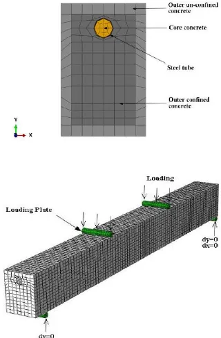
The flexural performance of prestressed concrete-encased CFST beams with high-strength concrete and steel was analyzed using nonlinear finite element models in ABAQUS software [19], as shown in Figure 2. In the nonlinear analysis, convergence is easier to obtain by applying the load thru controlling deflection, so that for all cases, the deflection-controlled load was slowly increased until reaching the ultimate capacity of the beam.
3. 1. Material Constitutive Models
3. 1. 1. Steel Tube, Rebar, and Prestressed Strand
Numerous stress-strain models, including elastic-plastic, elastic-perfectly plastic with linear hardening or multi-linear hardening for steel tubes and rebars are available in the literature. However, the effects of using various stress-strain models on the ultimate strength and behavior of HS-PCE-CFST beams is negligible. In this study, an elastic-plastic model with linear hardening was assimilated to establish the stress-strain relationship of
Figure 2. FE modeling of HS-PCE-CFST beams
the steel tube, where the strain hardening modulus was considered as to be 0.005Es (in which
E
s is the elasticmodulus of steel) [20]. Also, the steel tube yield strength between 345-740 MPa and ultimate strength of the steel tube between 448-843 MPa is considered.
Furthermore, the bi-linear stress-strain model, proposed by Zhao [21], was implemented to signify the stress-strain relation of the rebar. The yield and ultimate strength of longitudinal rebar are considered 400 and 600 MPa, respectively. These numbers are equal to 235 and 350 MPa for the stirrup. It should be noted that Young's modulus and Poisson's ratio of the longitudinal bar and steel tube were equal to 200,000 MPa and 0.3, respectively.
To accurately estimate the experimental curve that resembled two straight lines connected by a curved knee, the Ramberg-Osgood curve can be utilized. Therefore, in order to describe the behavior of prestressed strand, the bi-linear stress-strain elastic-plastic model, proposed by Ramberg-Osgood, was adopted. The first almost straight portion of this curve is asymptotic to the inclined dotted straight lines with a slope of Eps at the origin. The Eps
modulus (which is slightly larger thanEps) is determined such that the Ramberg-Osgood curve matches the elastic straight line (with the slope of Eps) at the point 0.7fpu, and
thus the curvature of the knee is regulated using the shape parameter (constant m, equal to 4) [22]. Also, the prestressing strand with Grade 270 is used.
3. 1. 2. Concrete In this study, concrete with a
compressive strength of less than 70 MPa and concrete with a compressive strength of more than 70 MPa were respectively considered as normal- and high-strength concretes. The admissible range of Poisson's ratio for concrete with normal strength is between 0.15 and 0.25, which is generally assumed to be 0.2 in the analyses. According to studies, Logan et al. [23] determined that the average Poisson's ratio of high-strength concrete is equal to 0.17, however, the use of 0.2 for high-strength concrete is suggested to be acceptable up to strength 124 MPa. Therefore, in this study, the Poisson's ratio of 0.2 was considered for all concretes.
In order to model the nonlinear behavior of concrete in the ABAQUS software [19], the concrete damaged plasticity (CDP) was used, which takes advantage of the isotropic damaged plasticity concept [19]. In the CDP model, the default values of 0.1 for the flow potential eccentricity, 0 for the viscosity parameter, 1.16 for the ratio of compressive strength under biaxial loading to uniaxial compressive strength ( bo
c
f
f = f ), and 0.67 for
calibrated with experimental results. As can be seen in Figure 2, due to different confinement conditions, concrete is categorized into three parts of outer un-confined, outer un-confined, and the core concrete of CFST. Then, the uniaxial stress-strain model recommended by Hognestad [24], Han et al. [25], Elchalakani et al. [26], and Han et al. [27] were respectively applied to outer un-confined, outer un-confined, core concrete of CFST in beams with normal-strength concrete and CFST core concrete in beams with high-strength concrete, within the nonlinear finite element model.
3. 2. Steel-concrete Interaction In order to
introduce the contact of steel tube with the core and outer concrete in the normal direction, hard contact interaction, and Mohr-Coulomb friction model in the vertical direction were defined using the surface-to-surface contact in ABAQUS. Such contact requires a pair of master and slave surfaces, in which the slave surface needs to be from softer material and finer mesh, compared to the master surface so as to reduce numerical errors [19]. Therefore, concrete surfaces were considered to be a slave, and steel tube surfaces as a master. It is worth mentioning that in the Mohr-Coulomb friction model, a relative slip is formed between the surfaces until the stress exceeds the shear stress limit (i.e. the bond stress,
bond). When the relative slip is formed, the shear force was calculated by a friction coefficient and the contact pressure. The friction coefficient was taken to be 0.4 in this study, once calibration was performed with experimental results [5].3. 3. Mesh and Elements Description Loading
plates, supports, and concrete components were modeled using 8-node solid elements with reduced integration; rebars and prestressed strands with the 2-node truss elements; and steel tubes with the 4-node conventional shell (S4R) elements. Embedded element technique was used to model the contact of rebar and prestressed strands with concrete in ABAQUS. In this method, a region of the model can be embedded within a host region of the model, such that the degrees of freedom of the embedded region is constrained to the interpolated values of the corresponding degrees of freedom of the host element. Thus, the rebars and prestressed strands are considered to be fully coupled with the concrete, and the interaction between steel and concrete is calculated by the software. In order to convergence in the analysis and reduce the computational time, by performing a trial and error, meshes of size 60 and appropriate partitions were selected according to Figure 2.
3. 4. Loading and Boundary Conditions
According to Figure 1, the boundary conditions were applied as simple supports. The beams were loaded in
two steps. In the first step, the initial prestressing was simulated by means of applying a concentrated load in the prestressed strand, and in the second step, the 4-point external loading was simulated by applying a deflection to the loading plates, in that the deflection at mid-span of the model is equal to deflection in the middle of the experimental specimen (as shown in Figure 2). The loading plate was assumed to be a rigid block with a stiffness sufficiently large, whose deformation can be ignored.
4. VERIFICATION OF FE MODEL
The finite element model developed in this study is verified using the experimental data of prestressed concrete-encased CFST. The verification is performed for the prestressed concrete-encased CFST that were experimentally examined by Rahmani et al. [18]. So, T1P1E1 specimen is used, which its details have shown in section 2. The rest of the modeling specification is also applied in the ABAQUS software based on section 3. Figure 3 shows a comparison between the curve of moment-displacement at the mid-span of the experimental and numerical specimen. A good agreement was obtained between experimental and numerical results for T1P1E1 specimen. Figure 4 shows a comparison between experimental and numerical results of concrete cracking and failure mode of T1P1E1 specimen. The failure was failure shear-flexural failure combined with concrete crushing in compression (shear-compression failure). Concrete cracking was established by the maximum principal plastic strain in the FEA model and the cracks are perpendicular to the orientation of the maximum principal plastic strain. In general, a good agreement was found between the experimental and numerical specimens in terms of the crack distribution of concrete. Also, Figure 5 shows the curve of the moment
Figure 3. Comparison of predicted and measured [18] M-um
Figure 4. Comparison of failure modes between predicted and test specimens [18]
versus extreme compression fiber strain of concrete in the mid-span for the above specimen experimentally and numerically that a good agreement between the obtained results.
5. PARAMETRIC STUDY
In this section, a parametric study is carried out to investigate the effects of steel tube yield strength
(
)
ys
f
(345, 435, 525, 630, 740 MPa), compressive cylinder strength of the core
(
)
, cu core
f and outer concrete
(
fcu out,)
(60, 70, 80, 90 MPa), and the steel tube diameter to section width ratio (0.2, 0.3, 0.4) on the flexural behavior of HS-PCE-CFST beams. These beams were classified into four groups, details of which are given in Table 2. All beams have a width of 500 mm, a height of 800 mm, a length of 10,000 mm, and a shear span of 3100 mm. The beams have seven longitudinal bars with a diameter of 25 mm in the tension zone (bottom level) and a yield strength of 400 MP, five prestressed strands with a diameter of 15 mm (0.6 in), and Grade 270 in the tension zone (top level) with 10-mm diameter stirrups with spacing of 150 mm and a yield strength of 235 MPa. In addition, the steel tube with a diameter of 100 mm, a thickness of 2 mm, and a yield strength of 345 MPa was
Figure 5. Comparison of predicted and measured M-s relations [18]
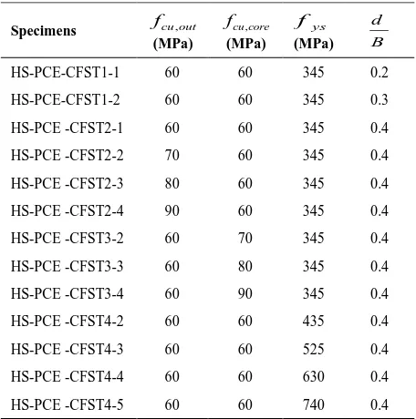
TABLE 2. Specimen information
d B ys f
(MPa)
,
cu core f
(MPa)
,
cu out f
(MPa) Specimens
0.2 345
60 60
HS-PCE-CFST1-1
0.3 345
60 60
HS-PCE-CFST1-2
0.4 345
60 60
HS-PCE -CFST2-1
0.4 345
60 70
HS-PCE -CFST2-2
0.4 345
60 80
HS-PCE -CFST2-3
0.4 345
60 90
HS-PCE -CFST2-4
0.4 345
70 60
HS-PCE -CFST3-2
0.4 345
80 60
HS-PCE -CFST3-3
0.4 345
90 60
HS-PCE -CFST3-4
0.4 435
60 60
HS-PCE -CFST4-2
0.4 525
60 60
HS-PCE -CFST4-3
0.4 630
60 60
HS-PCE -CFST4-4
0.4 740
60 60
HS-PCE -CFST4-5
placed in the compression zone of the section. The concrete cover was 50 mm and the distance from the center of prestressed strands to the longitudinal bar level was 95 mm. Each of the strands was prestressed with a force of 150 kN.
5. 1. Flexural Behavior The moment-curvature
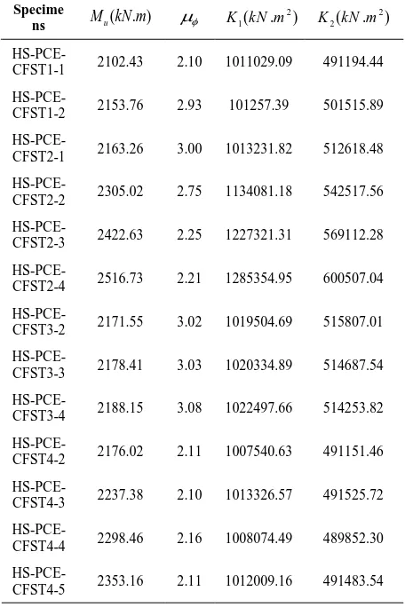
curves of beams are presented in Figures 7-10. According to the curves, the ultimate flexural capacity, flexural stiffness and the curvature ductility of the beams are determined, as shown in Table 3. The effects of various parameters are investigated in the following sections.
5. 1. 1. Failure Mode Figure 6 demonstrates
concrete cracking for all beam. As it is observed, all beams fail in flexure mode. At first, the bending cracks are formed within the tension zone and pure flexural span. With the extension of these cracks, small diagonal cracks appear in the shear span. As the loading increases, the depth of bending cracks increase and once the concrete is crushed in the compression zone, flexural failure is observed at the vicinity of the concentrated load. In the nonlinear finite element model, concrete cracking is established thru maximum principal plastic strain and the cracks are perpendicular to the orientation of such strain. The ultimate bending moment (
u M ), shown in Table 3, corresponds to the maximum compressive strain of the concrete (0.0035).
Figure 6. The failure mode of specimens
extreme compression fiber of concrete reaches the maximum compression strain,
u
, to the curvature when the longitudinal reinforcement first reaches the yield strength,
y”.Flexural stiffness is an important parameter in determining the buckling capacity of a member and evaluating elastic deformations and internal forces of a structure [29]. In this section, two types of flexural stiffness are investigated. The first is the initial flexural stiffness,
1
K which is defined with regard to secant stiffness corresponding to a moment equivalent to 0.2 of the ultimate moment [30]. The second is the serviceability level flexural stiffness (elastic-plastic stiffness),
2
K corresponding to the secant stiffness at a moment equivalent to 0.6 of the ultimate moment [31]. The values of initial flexural stiffness and serviceability level stiffness for all beam specimens are presented in Table 3.
5. 2. Effect of Compressive Strength Of Concrete
In order to assess the influence of compressive cylinder strength of the outer concrete on the behavior of HS-PCE-CFST beam, compressive cylinder strengths of 60, 70, 80 and 90 MPa were studied. The moment-curvature curve of the beams is illustrated in Figure 7. The beams with a compressive cylinder strength of the outer concrete of 60-80 MPa have five characteristic points. Point A, is the starting point of concrete cracking in the tension zone. Point B denotes the outset of longitudinal bar yielding. Point C represents the beginning of steel tube yielding in the compression zone. Point D signifies the onset of stirrup yielding, and point E is the point at which strain at extreme compression fiber of concrete reaches the compression failure strain. On the other hand, beams with the concrete compressive cylinder strength of 90 MPa have six characteristic points, in which the fifth point indicates the onset of prestressed strand yielding after the start of stirrup yielding and before of the point corresponds to the ultimate tensile strain of concrete.
As shown in Figure 7 and Table 3, with increasing compressive cylinder strength of the outer concrete, increase in the ultimate flexural capacity of cross-section, initial flexural stiffness, and serviceability level flexural stiffness is observed. However, sections with higher compressive strength of the outer concrete, as compared
TABLE 3. Results of flexural capacity, curvature ductility, and stiffness
2 2( . )
K kN m
2 1( . )
K kN m
( . ) u M kN m Specime
ns
491194.44 1011029.09
2.10 2102.43
HS-PCE-CFST1-1
501515.89 101257.39
2.93 2153.76
HS-PCE-CFST1-2
512618.48 1013231.82
3.00 2163.26
HS-PCE-CFST2-1
542517.56 1134081.18
2.75 2305.02
HS-PCE-CFST2-2
569112.28 1227321.31
2.25 2422.63
HS-PCE-CFST2-3
600507.04 1285354.95
2.21 2516.73
HS-PCE-CFST2-4
515807.01 1019504.69
3.02 2171.55
HS-PCE-CFST3-2
514687.54 1020334.89
3.03 2178.41
HS-PCE-CFST3-3
514253.82 1022497.66
3.08 2188.15
HS-PCE-CFST3-4
491151.46 1007540.63
2.11 2176.02
HS-PCE-CFST4-2
491525.72 1013326.57
2.10 2237.38
HS-PCE-CFST4-3
489852.30 1008074.49
2.16 2298.46
HS-PCE-CFST4-4
491483.54 1012009.16
2.11 2353.16
HS-PCE-CFST4-5
to normal compressive strength, demonstrate lower ductility, which is due to the effect of confinement generated by the stirrups. Chen [32] found similar results, stating that with increasing compressive strength of the outer concrete, the steel tube is further encased from the outside, and thus its outward buckling is prevented.
Four types of compressive cylinder strength (60, 70, 80, 90 MPa) were considered for the core concrete in order to investigate the effect of compressive strength of core concrete on the HS-PCE-CFST beam behavior. The moment-curvature curve of these beams is shown in Figure 8. All beams have five characteristic points. Point A, is the starting point of concrete cracking in the tension zone. Point B denotes the outset of longitudinal bar yielding. Point C represents the beginning of steel tube yielding in the compression zone. Point D signifies the onset of stirrup yielding, and point E is the point at which strain at extreme compression fiber of concrete reaches the compression failure strain. As highlighted in Figure 8 and Table 3, these beams exhibit similar flexural behavior. It can be stated that the compressive strength of the core concrete has no influence on the ultimate moment, initial and serviceability level flexural stiffness, and ductility. Therefore, it is inferred that the ultimate flexural strength, ductility, and the flexural stiffness of HS-PCE-CFST beams is governed by changing the mechanical properties of the outer concrete; while the flexural behavior of these beams is not affected by mechanical properties of the outer concrete. It should be noted that the steel tube increases the confinement of the core concrete and its compressive strength so that low compressive strength can be used for core concrete, and change its strength does not have much effect on the flexural capacity of the section. Moreover, based on the studies conducted by Javed et al. [14] on the behavior of CFSTs with high-strength concrete, it was witnessed that increase in the compressive strength of the core concrete, augmented the steel tube confinement, and consequently, the inward buckling of the steel tube is further controlled. Also, they found that the ultimate flexural strength and ductility of the CFST beams could be controlled by varying mechanical properties of the core concrete.
5. 3. Effect of Steel Tube Yield Strength The effect
of steel tube yield strength on the flexural behavior of the HS-PCE-CFST beams was investigated thru 5 types of
Figure 8. Comparison of M-φ relationships for different compressive strengths of core concrete
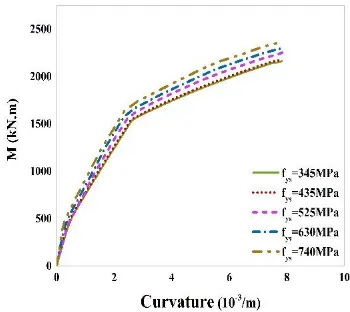
steel tube yield strength (345, 435, 525, 630, 740 MPa). The moment-curvature curve of the beams is sketched in Figure 9. It was observed that the beam with a steel tube yield strength of 345 MPa has five characteristic points, as described in section 5.2. However, the steel tube does not yield with increasing its yield strength, and hence the remaining beams have four characteristic points. Table 3 explains that with increasing steel tube yield strength by 114%, the ultimate bending moment of cross-section increases by 8%, which is, firstly, due to the increased confinement generated by the steel tube with higher strength, and secondly, because of an increase in the strength of steel tube. On the contrary, a rise in the strength of steel tube has no effect on the ductility and stiffness of these beams. The outer concrete, by encasing the steel tube, prevents the outward buckling of the steel tube. Also, the core concrete prevents the inward buckling of the steel tube. As a result, thin-walled steel tubes can be used in the Hs-PCE-CFST beams and the effect of steel tube yield strength is negligible. Similar results have been reported by Javed et al. [14] for the CFST members.
5. 4. Effect of d
B
Ratio Three values of 0.2 to 0.4
were considered for the ratio of steel tube diameter to section width (d
B) in the HS-PCE-CFST beams to
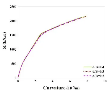
examine the effect of this parameter on the flexural behavior of these beam types. The moment-curvature curve of the beams is depicted in Figure 10. All beams have five characteristic points, as described in section 5.2. According to Figure 10 and Table 3, with increasing of
d
B
ratio by 100%, the ultimate bending moment,initial flexural stiffness, and serviceability level flexural stiffness respectively increase by 3, 22 and 4.4%. Therefore, it is perceived that the section dimensions can be reduced by increasing the diameter of the steel tube.
Figure 10. Comparison of M-φ relationships for different d
B ratios
6. CONCLUSION
In this study, high-strength concrete and steel were used to investigate the flexural behavior of HS-PCE-CFST beams in order to extend the design codes. For this purpose, a total of 13 HS-PCE-CFST beams were modeled by varying compressive cylinder strength of the core and outer concrete, steel tube yield strength, and ratio of steel tube diameter to section width via ABAQUS software. The ultimate bending moment, failure mode, flexural stiffness, and ductility were also investigated. It was noticed that all beams have flexural failure modes. An increase in the compressive cylinder strength of the outer concrete by 50%, leads to an increase in the ultimate flexural capacity of the section by 16%, the initial flexural stiffness by 27%, and the serviceability level flexural stiffness by 17%, as well as a reduction in the section ductility. It was also discerned that compressive cylinder strength of the core concrete has no influence on the ultimate flexural capacity, initial flexural stiffness, serviceability level flexural stiffness and ductility of the section. Therefore, in HS-PCE-CFST beams, we can use core concrete with low compressive strength. Furthermore, varying the yield strength of steel tube from 345 to 740 MPa slightly increases the ultimate bending moment of cross-section, while it does not affect the section ductility and flexural stiffness. Also, no inward and outward buckling of the steel tube was observed due to the confinement provided by the outer concrete and the support provided by the core concrete. So thin-walled steel tubes or steel tube with low strength can be used in these sections. By changing the ratio of diameter to section width from 0.2 to 0.4, the ultimate bending moment and serviceability level flexural stiffness increase marginally, but the initial flexural stiffness is significantly elevated (22%). As a result, the compressive cylinder strength of the outer concrete has a noticeable effect on the flexural behavior of the HS-PCE-CFST beam, but in contrast, the compressive cylinder
strength of the core concrete has no contribution. Consequently, it was concluded that by increasing the diameter of the steel tube as well as the strength of materials, section dimensions can be reduced. Moreover, due to the effect of strength on the behavior of these beam types, different relationships should be calculated for the design of these beams with normal- and high-strength materials.
7. REFERENCES
1. Webb, J., Beyton, J.J., “Composite concrete-filled steel tube columns” In Proceedings of structural engineering conference. Adelaide: The Institution of Engineers Australia, 181-5, (1990). 2. Han, L.H., Li, W., Bjorhovde, R., “Developments and advanced
applications of concrete-filled steel tubular (CFST) structures: Members”, Journal of Constructional Steel Research, Vol. 100, (2014), 211-228.
3. Razzaghi, M.S., Esfandyary, R., Nateghi, A., “The effects of internal and external stiffners on hysteretic behavior of steel beam to CFT column connections”, International Journal of Engineering, Transactions A: Basics, Vol. 27, No. 7, (2014), 1005-1014.
4. Abdollahzadeh, G.R., Yapang Gharavi, S., Hoseinali Beigi, M., “Analytical experimantal investigation of I beam-to-CFT column connections under monotonic loading (research note)”,
International Journal of Engineering, Transactions B: Applications, Vol. 27, No. 2, (2014), 293-306.
5. An, Y.F., Han, L.H., Roeder, C., “Flexural performance of concrete-encased concrete filled steel tubes”, Magazine of Concrete Research, Vol. 66, No. 5, (2014), 249-267.
6. Han, L.H., An, Y.F., Roeder, C., Ren, Q.X., “Performance of concrete-encased CFST box members under bending”, Journal of Constructional Steel Research, Vol. 106, (2014), 138-153. 7. Nateghi A., F., Vatandoost, M., “Seismic retrofitting RC
structures with precast prestressed concrete braces ABAQUS FEA modeling”, International Journal of Engineering, Transactions C: Aspects, Vol. 31, No. 3, (2018), 394-404. 8. Tuan, C.Y., “Aurora arch bridge-Confined concrete system
speeds construction of Walkway span”, Concrete International, Vol. 26, No. 4, (2004), 64-67.
9. Christopher, Y., Tuan, C.Y., “Flexural behavior of non-posttensioned and non-posttensioned concrete-filled circular steel tubes”, Journal of Structural Engineering, Vol. 134, No. 6, (2008), 1057-1060.
10. Deng, Y., Tuan, C.Y., Zhou, Q., Xiao, Y., “Flexural strength analysis of non-posttensioned and post-tensioned concrete-filled circular steel tubes”, Journal of Constructional Steel Research, Vol. 67, (2011), 192-202.
11. Zhan, Y., Zhao, R., Ma, Z.J., XU, T., Song, R., “Behavior of prestressed concrete-filled steel tube (CFST) beam”, Engineering Structure, Vol. 122, (2016), 144-155.
12. Xiong, M.X., Xiong, D-X., Richard, Liew, J.Y., “Flexural performance of concrete filled tubes with high tensile steel and ultra-high strength concrete”, Journal of Constructional Steel Research, Vol. 132, (2017), 191–202.
13. Eurocode 4., “Design of composite steel and concrete structures, part 1.1: general rules and rules for building”, BS EN 1994-1-1, London, UK, (2004).
15. GB50936, “Technical code for concrete filled steel tubular structures”, Chinese Standard, (2014).
16. A.I.o.S.C. (AISC), “Load and resistance factor design specification for structural steel buildings”, American Institute of Steel Construction, Chicago, USA, (2005).
17. CIDECT, International Committee for the Development and Study of Tubular Structures.
18. Rahmani, Z., Naghipour, M., Nematzadeh, M., “Structural Behavior of Prestressed Self-Compacting Concrete-Encased CFST Beams”, Computers and Concrete, submitted.
19. ABAQUS., Standard user's manual, version 6.12. Providence, RI, USA, Dassault Systemes Corp, (2012).
20. Thai, H.T., UY, B., Khana, M., Tao, Z.h., Mashiri, F., “Numerical modelling of concrete-filled steel box columns incorporating high strength materials”, Journal of Constructional Steel Research, Vol. 102, (2014), 256–265.
21. Zhao, X.M., Wu, Y.F., Leung, A.Y.T., “Analysis of plastic hinge regions in reinforced concrete beams under monotonic loading”,
Engineering Structures, Vol. 34, (2012), 466-482.
22. Hsu Thomas, T.C., Mo, Y.L., “Unified theory of concrete structures”, United Kingdom: John Wiley & Sons, Ltd, (2010). 23. Logan, A., Choi, W., Mirmiran, A., Rizkalla, S., Zia, P.,
“Short-term mechanical properties of high-strength concrete”, ACI Materials Journal, Vol. 106, No. 5, (2009), 413.
24. Hognestad, E., “A study of combined bending and axial load in reinforced concrete members. Bulletin 399”, University of Illinois Engineering Experimental Station, Vol. 111, (1951), 128.
25. Han, L.H, An, Y.F., “Performance of concrete-encased CFST stub columns under axial compression”, Journal of Constructional Steel Research, Vol. 93, (2014), 62–76.
26. Elchalakani, M., Karrech, A., Hassanein. M.F., Yang, B., “Plastic and yield slenderness limits for circular concrete filled tubes subjected to static pure bending”, Thin-Walled Structures, Vol. 109, (2016), 50–64.
27. Han, L.H., Yao, G.H., Tao, Z., “Performance of concrete-filled thin-walled steel tubes under pure torsion”, Thin-Walled Strut, Vol. 45, No. 1, (2007), 24-36.
28. Rabczuk, T., Eibl, J., “Numerical analysis of prestressed concrete beams using a coupled element free Galerkin/finite element approach”, International Journal of Solids and Structures, Vol. 41, (2004), 1061–1080.
29. Han, L.H., An, Y.F., Roeder, C., Ren, Q.X., “Performance of concrete-encased CFST box members under bending”, Journal of Constructional Steel Research, Vol. 106, (2014), 138-153. 30. Han, L.H., “Flexural behaviour of concrete-filled steel tubes
Journal of Constructional Steel Research, Vol. 60, (2004), 313-337.
31. Varma, A.H., Ricles, J.M., Sause, R., Lu, L.W., “Seismic behavior and modeling of high strength composite concrete-filled steel tube (CFST) beam-columns”, Journal of Constructional Steel Research, Vol. 58, (2002), 725-758.
32. Chen, Y.S., “Testing and modeling tensile stress-strain curve for prestressing wires in pailroad ties”, B. S., University of Tamkang, Master of science, Kansas State University , Manhattan, (2016).
Flexural Performance of High-strength Prestressed Concrete-encased Concrete-filled
Steel Tube Sections
Z. Rahmania, M. Naghipoura, M. Nematzadehb
a Faculty of Civil Engineering, Babol Noshirvani University of Technology, Babol, Iran b Department of Civil Engineering, University of Mazandaran, Babolsar, Iran
P A P E R I N F O
Paper history: Received 20 May 2019
Received in revised form 30 June 2019 Accepted 05 July 2019
Keywords: Flexural Behavior Prestressed Concrete Concrete-filled Steel Tube Confinement
High-strength Material
هدیکچ
نتب و دلاوف زا بکرم عطاقم هلول لماش هک
یم نتب رد طاحم نتب اب هدشرپ یاه تمواقم لیلد هب صقاون یاراد امومع دنشاب
یم نتب نیئاپ یششک هلول بیکرت زا یبسانم شور کی ، نیاربانب دنشاب
( نتب اب هدشرپ یاه
CFT
لباک و ) شیپ یاه هک هدینت
یحارط یاهامنهار نینچمه .دش هتفرگ راکب ،هدش طاحم نتب رد یم لامرن تمواقم اب حلاصم یارب جیار
یارب زاین و دنشاب
تمواقم اب دلاوف و نتب زا قیقحت نیا رد یحارط هعسوت روظنم هب نیاربانب ،دراد دوجو لااب تمواقم اب حلاصم اب عطاقم یسررب نا ،هتسه نتب یگدشروصحم یور رب نتب و دلاوف تمواقم ریثأت یسررب فده هک تسا هدش هدافتسا لااب و عطقم حطس هزاد
نتب اب هدش رپ یدلاوف هلول لماش یاهریت یشمخ راتفر
ˏ
نتب رد طاحم
ˏ
شیپ لااب تمواقم اب حلاصم اب هدینت
(
HS-PCE-CFST )
یم ریت هدزیس ،ور نیا زا .دشاب
HS-PCE-CFST
مرن اب سوکابآ دودحم ناملا رازفا
( ABAQUS FEA )
م ،نآ رد یلصا یاهرییغتم هک تسا هدش یزاسلدم هناوتسا هنومن یراشف تمواقم ،یدلاوف هلول میلست تمواق
و هتسه نتب یا
یم عطقم یانهپ هب یدلاوف هلول رطق تبسن و ینوریب نتب تحص روظنم هب زین یبرجت جیاتن زا .دشاب
دودحم ناملا لدم یجنس
لکش ،یشمخ رگنل یاهرتماراپ .تسا هدش هدافتسا وم اهریت یگتخیسگدم و یشمخ یتخس ،یریذپ
.تسا هتفرگ رارق یسررب در
یم ناشن یسررب جیاتن ،یدلاوف هلول میلست تمواقم و هتسه نتب یراشف تمواقم ،ینوریب نتب یراشف تمواقم نایم زا هک دهد
عطقم یانهپ هب رطق تبسن شیازفا زین و دراد یشمخ یاهرتماراپ رییغت یور رب یرتشیب رثا ینوریب نتب یراشف تمواقم رییغت شیازفا ببس هیلوا یشمخ یتخس رد ریگمشچ شیازفا و سیورس حطس یشمخ یتخس و ییاهن یشمخ رگنل رد زیچان
یم .ددرگ
![Figure 1. Overview of test arrangement and dimension of test specimens (unit: mm) a) T1P0E1, T2P1E1, T1P1E2, T1P2E1, T1P1E1 specimens, b) T0P1E1 specimen [18]](https://thumb-us.123doks.com/thumbv2/123dok_us/16989.2001711/3.595.66.277.537.702/figure-overview-test-arrangement-dimension-specimens-specimens-specimen.webp)
![Figure 3. Comparison of predicted and measured [18] M-um relations](https://thumb-us.123doks.com/thumbv2/123dok_us/16989.2001711/5.595.328.521.560.714/figure-comparison-predicted-measured-m-um-relations.webp)