A Simple, Low Cost Optical Tilt Sensor
Subir Das
Department of Applied Electronics and Instrumentation Engineering, Murshidabad College of Engineering and Technology, Berhampore, Murshidabad, West Bengal, India
E-mail: [email protected]
Abstract—For the purpose of kinematic monitoring system a prototype relatively simple and low cost optical Tilt (or inclination) sensor with sensitivity of 50mV/º and a working range of ±50º is presented in this paper. The sensor consists of a cylindrical shaped transparent container with half filled color liquid and an optical source and detector. The sensor principle based on temporal changes in light intensity due to variation of optical path length through a liquid medium with the tilt angel of sensor module. This change of light intensity detected by an optical detector & eventually processed by a signal processing circuit (SPC) to display the tilting (or inclination) value digitally. Proposed sensor’s exhibits an accuracy of 0.8º and resolution of 0.09º respectively.
Index Terms—tilt sensor, intensity of light, optical path length, SPC
I. INTRODUCTION
Tilt (or inclination) sensor measures the horizontality of a system plane or the rotation of a body with respect to the gravity field. It is widely used in industry or any other fields such as: construction of bridges, oil drilling, aviation and marine, industrial automation, intelligent platform, instruments for wheel alignment, optical systems and more in general in many applications in the field of mechatronics, geophysical monitoring, machine tool leveling, medical positioning – monitoring and many others. There are several kinds of commercial sensor for measuring the tilt angle, is available in the market.
But still researchers are discovered or invented new methods of measurement techniques to reduce the system complexity in existing solution and try to find out the better accuracy, sensitivity and high resolution in low range of economic policies.
These tilt (or inclination) sensors can be divided into three types: pendulums, liquid inclination sensors and mass spring inclination sensors. They all have their advantage and disadvantage in terms of their working principles.
Pendulums [1], [2] are based on a mass suspended by a rope or a hinged bar. Under the influence of the gravity field the mass will force the rope or hinged bar in a vertical or horizontal reference orientation; this is measured in terms of tilt angel. The advantages of these sensors have their wide range. On the other hand the friction in the hinged bar will reduce the accuracy. Also it
Manuscript received September 2, 2013; revised February 14, 2014.
is interfered by the external factors, such as the vibration caused by mechanical shock.
In mass spring inclination sensor [3] the proof mass suspended on a spring and it is bent the spring under the influence of sensor body rotation with the gravitational fields. Due to the spring elasticity properties the mass will oscillate in the sensor body and made a dynamic error in the system.
With liquid inclination sensor [4], two concepts are possible: an almost completely filled liquid reservoir with one air bubble or a half filled liquid reservoir with a horizontal liquid surface. In the first case, the top of the reservoir is curved. If the sensor is tilted, the air bubble rises to the highest point in the reservoir. This displacement is measured. In the second case, the liquid surface forms a horizontal reference, which is measured. Both types of liquid inclination sensor have simple in structure and provide better accuracy with low cost.
All these three type of sensor measures the tilt angel electronically. So these physical changes of sensor medium are converted into electrical signal based on some electrical properties such as resistive [5], capacitive [6], inductive [7]-[10] and optical [11]-[16]. The resistive [5] type tilt measurement system gives a wide linear range and a high resolution but it is affected by temperature and electromagnetic interference. An innovative low cost micromechanical capacitive [6] type measurement system implies a good frequency response; hence they are useful for dynamic measurement. But its major drawbacks are nonlinearity behavior on account of edge effects and high output impedance on account of their small capacitance value. Moreover, the capacitance may be changed because of the presence of dust particles and moisture or because of temperature changes. The uses of magnet & magnetic fluid to measure the inclination [7]-[10] introduced complex experimental setup and can be affected by electromagnetic interference. Excluding these above measurement technique optical type measurement [11]-[16] system have advantages over other type of techniques in that they can provide greater sensitivity, better accuracy, wide frequency range, and dynamic ranges and easy to experimental setup also it is immune to electromagnetic interference. From these advantages, optical techniques may be ideal for the development of sensors for the measurement of small tilt angel.
with a large measurement range using four Fiber Bragg Gratings (FBGs) attached on a cylindrical cantilever-based pendulum is demonstrated in [14], [15]. A tilt accuracy of ±0.2° and resolution of 0.013° in the range of ±40° was achieved. The paper [16] deals with the theory, design, fabrication and test results of a fiber-optic tilt sensor based upon the modulation of light intensity with the change in the level of mercury (Hg) surface with the tilt. The sensitivity of the sensor realized in [16] is 0.013 Vmrad-1 and the maximum range covered is 53.4 Vmrad. Small in size, opto-electromechanical tilt sensor fabricated by MEMS process is presented in [17] which required array of photo detector to measure the position of pendulum with the tilt angel variation. A fiber optic cantilever tilt sensor [18] presents simple structure with the measuring range of ±30°.When the sensor is tilted, the free end of the cantilever experiences deflections, caused by the tilt and unavoidable accelerations. These deflections can be measured using a position sensitive device (PSD) provided that light propagates through the fiber and creates a light spot on the PSD surface. From the measured positions, tilt angles in two orthogonal axes may be derived.
In this paper, a simple low cost liquid inclination type tilt angel measurement system has been reported which contributed better accuracy, linearity, repeatability within a small space range. This method has been designed by the principle of optical light intensity variation method due to the changes of optical path length through the liquid medium as presented by Beer-Lambert Law [19]. Eventually the variation of light intensity has been converted into voltage variation and calibrated into measured range of tilt angel by the signal processing circuit (SPC) [20]. Since it has an advantage over the other optical measurement system (like mercury based intensity modulation technique [16], opto-electromechanical type [17], cantilever type fiber optic sensor [18]) that the light intensity largely independent of the reflector position and single photo-detector unit has been minimized the complex detection architecture. The prototype module has been operates in the range of ±50 degree. We proved successfully that this system works as a small tilt sensor. The introduction is followed by a representation of the working principle, constructional details, the experimental investigation, and a series of discussion topics based on the experiment.
II. THEORETICAL BACKGROUND
In the field of spectrophotometry the light absorption capability of a substance or concentration of absorbing spices in a solution has been measured utilizing the Beer-Lamberts Law (or Beer’s Law). A spectrophotometer is employed to measure the amount of light that a sample absorbs by passing a beam of light through a sample and measuring the intensity of light after reaching a detector. The absorption of light by a substance in a solution can be described mathematically in “(1)”:
A = εbc (1)
where A is called absorbance of a substance or sample in a solution and it’s become linear with the product of the molar absorptivity (ε) of absorber in a solution, the path length (b) i.e. light travelling distance through the solution and molar concentration (c) of absorbing spices in a solution. Also the variation of light intensity has been expressed mathematically in “(2)”:
T = I / I0 (2)
The intensity ratio between transmitted light (I) through an absorber & incident light (I0) is called
transmittance (T). The Beer’s law states that there is a logarithmic dependence between the transmittance of light through a solution and the absorbance of a substance in a solution and this can be derived as in “(3)”
A = - = - (3)
From the equation (3), it is concluded that the change of light intensity depends on molar absorptivity, path length and molar concentration respectively. So utilizing the spectrophotometer molar concentration of a substance in a solution has been measured if molar absorptivity and path length is known for a particular experiment. Hence this spectrophotometer principle also useful for measuring tilt angel if the molar absorptivity and molar concentration is kept constant and vary the path length with the sensor inclination. This variation of path length has been converted into electrical energy by changing the light intensity between source and detector. So it is obvious that if a sensor module can be designed by using this criterion then it may sense the inclination of a horizontal surface electronically.
III. EXPERIMENTAL PROCEDURE
A. Working Principal
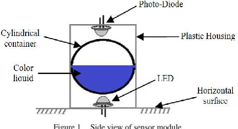
To measure the small tilt angle a liquid based optical sensor module has been developed and tested. It is designed by a transparent cylindrical shaped half filled color liquid container, a LED (optical source) and a Photo-Diode (photo-detector). All of these equipments are arranged in a plastic housing to keep a rigid support of liquid container between the optical source and detector as shown in Fig. 1.
Figure 1. Side view of sensor module
transmitted light from optical source (LED) has been reached to the detector (photo-diode) after traveling through the half filled liquid medium and half filled air medium in a container. Hence the sensor module (i.e. plastic housing) inclined from the horizontal surface; the half filled liquid in a cylindrical container acts as a pendulum so, the liquid are shifted either right or left side of the container wall without changing its shape. This may cause the variation of light travelling distance (i.e. path length) through the liquid medium and effect of these could be change in light intensity between the source and detector as stated by Beer’s law. To establish this conclusion a mathematical model has been derived using Fig. 2.
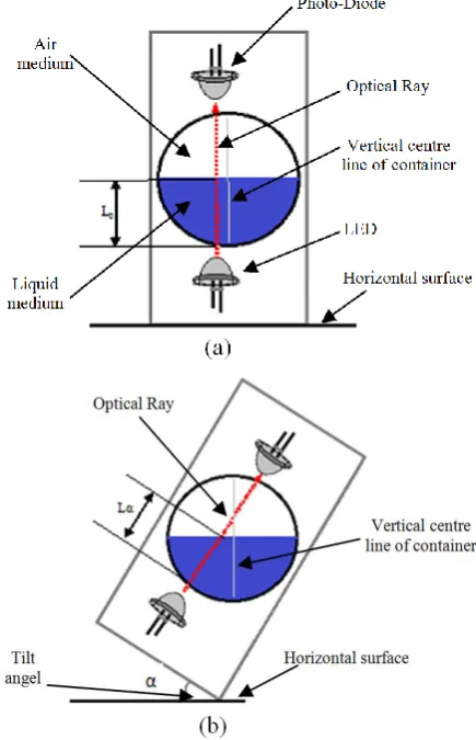
Figure 2. Side view of sensor module; (a) Initial position (i.e. without inclination) (b) Inclined position by the angel of α
The changing intensity of light at the detector is depend on the three parameters of color liquid medium in a container like molar absorptivity of liquid, molar concentration of liquid and light travelling path length through the liquid. In this proposed sensor design the molar absorptivity & molar concentration of liquid medium is constant so, the path length can be changed due to inclination of sensor. From Fig. 2(a) it is obvious that the optical source & detector does not placed in centre of the container wall because if the optical ray passed through the vertical centre line of container (i.e. the length of container bottom surface diameter) then at inclined position of the sensor module the optical path
length through the liquid medium always attains the same path length (i.e. radius of container bottom surface) due to exactly half filled liquid medium in a cylindrical container. For the variation of optical path length through the liquid medium at various inclined position, it is assume that the source & detector has been placed x cm away from the centre line and it has been proved successfully in the following mathematical analysis. At the initial condition, it is assumed that the optical path length through the liquid medium is Li, which is not equal
to the radius of the container because of shifting arrangement of optical source & detector from the centre line of the container as shown in Fig. 2(a). Now if the sensor module is inclined by an angel of α; it is observed that the optical path length through the liquid medium will be increased or decreased by the direction of sensor inclination. In Fig. 2(b) it is observed that due to inclination of sensor module at the right side by an angel of α; the optical path length through the liquid medium has been decreased by an amount of d from the initial path length Li and is represented as Lα so, it is expressed
in “(4)” as
Lα = Li – d (4)
To determine the value of d a right angle triangle has been established with the surface of liquid medium as hypotenuse, the perpendicular distance between optical path and centre line (i.e. x) of the container as base and variable path length d as height which is shown in Fig. 3.
Figure 3. Large view of intersection point between liquid medium & air medium where optical path length varies due to inclined position of
sensor module by the angel of α
From Fig. 3 it is implicit that the sensor inclination established a same angel (α) between the perpendicular distance x and the surface of liquid medium. So it can be written as
=
(5)
Hence, the variation of optical path length (Lα) through
the liquid medium; due to sensor inclination angel α as shown in “(4)” has been reconstructed in “(6)” as
Lα = Li – x (6)
between intensity and optical path length; is shown in “(7)” and “(8)” as
εbc = -
=
=
(7)
=
(8)
Due to sensor inclination angel α; the variation of light intensity has been expressed in “(9)” by rearranging “(7)” and “(8)” as
=
×
=
=
(9)
Due to the direction of sensor inclination, the variation of optical path length has been increased or decreased from the initial position. So, the variation of optical path length can be expressed as ± x by the representation of “(6)”. Equation (9) can be reformed with this version and shown in “(10)” as=
(10)
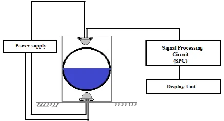
From “(10)” it is concluded that the light intensity of proposed sensor module has been increased at the positive inclined direction (i.e. inclined right side from initial position) or decreased at the negative inclined direction (i.e. inclined left side from initial position) with respect to the reference horizontal surface where the sensor module has been placed initially and recorded the light intensity at that position respectively. To calibrate this light intensity to the inclination of the target surface a signal processing circuit (SPC) and a microcontroller programmed based display unit has been used. The schematic diagram of this proposed measurement system is shown in Fig. 4.Figure 4. Schematic diagram of the proposed measurement system
B. Sensor Module Design Architecture
The sensor module consists of a transparent cylindrical shaped half filled color liquid container, a LED (optical source) and a Photo-Diode (photo-detector). The diameter
and height of cylindrical container are 30 mm and 80 mm respectively as shown in Fig. 5(a). The color liquid has been prepared by the mixing of visible light spectrum absorbing spices and water. In this proposed sensor the used absorbing spices is indigo (C16H10N2O2) which is a
dark blue crystalline powder and absorb the light spectrum; wavelength of 613nm (orange color in a spectrum). Due to this solvent in water it makes dark blue color solution and proper absorbing of light into this solution an orange color LED has been used. This liquid filled container has been placed horizontally in between of optical source & detector within an enclosed plastic housing. The distance between optical source & detector is 60mm and the dimension of plastic housing has 70×60×60 mm which are shown in Fig. 5(b).
Figure 5. (a) Half filled color liquid container (b) Side view of proposed sensor module
C. Signal Processing Circuit
For the purpose of digitization and conversion of light intensity into voltage variation a photo diode based signal processing circuit (SPC) has been used. The overall block diagram of SPC unit is shown in Fig. 6. This unit performed various steps of operation; firstly it converts the changing light intensity into voltage variation utilizing a photo diode and a current to voltage converter circuit and secondly this voltage variation confined in 0volt to 5volt range by zero and span adjustment circuit. Finally this range of voltage transformed into 256 levels of digital data using 8-bit ADC circuit.
Figure 6. Block diagram of SPC unit
D. Microcontroller Programmed Based Display Unit
defined Look-up-table data. The detailed flowchart of microcontroller program is shown in Fig. 7.
Figure 7. Flowchart of microcontroller program
IV. EXPERIMENTAL RESULT
In the proposed scheme the inclination of target or measuring surface has been measured by the principle of Beer’s law where the optical detector (photo diode) detects the variation of light intensity according to the variation of optical path length through the liquid medium in a container. The photo diode connects with a current to voltage converter circuit to gets a voltage variation with respect to the intensity. It is noticed that the developed current in this circuit due to the photo diode has been varies linearly from 87mA to 283mA due the inclination of sensor module in the range of -50º to +50º. The response current vs. tilt (inclination) angel curve is shown in Fig. 8. From Fig. 6 it is obvious that the output of current to voltage converter circuit has been calibrated in the range of 0 to 5 volt for the establishment of linear characteristics in the range of -50º to +50º. The calibrated output voltage (V0) has been measured and
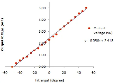
plotted against the inclination of target, which is shown in Fig. 9
Figure 8. Plot of measured current vs. tilt angel of target
Figure 9. Plot of output voltage (V0) of SPC vs. linear dispalcement of
target
In Fig. 9, it is obvious that the output voltage (V0) of
SPC unit approximately linear with the inclination of target. Hence we have calculated the non linearity of that curve utilizing best-fit straight line method and find the value of 2.28 & -3.21% FSO (Full Scale Output) at the inclination angel of -45º & 10º respectively. The obtained tilt angle sensitivities in linear regions is 50 mV/° for ± 50° range. The resolution of the tilt angle measurement depends on the signal/noise ratio, resolution of A/D converter and the aforementioned sensitivity. The typical
START
INITIALIZE I/O & MEMORY ALOCATION OF LOOK-UP-TABLE
SET RS=0
SEND 8-BIT TO LCD PORT FOR INTERFACE
SEND ENABLE SIGNAL TO LCD
SET TO DISPLAY ON; CURSOR UNDERLINES OFF.CURSOR BLINK ON.
SEND ENABLE SIGNAL TO LCD
8-BIT, 2 LINE MODES, 5X10 DOT FORMAT
SEND ENABLE SIGNAL TO LCD
CLEAR DISPLAY
INCREMENT; DISPLAY SHIFT ON
SET RS=1
SEND DATA FORM LOOK-UP-TABLE TO LCD
SEND ENABLE SIGNAL TO LCD
STOP
SEND ENABLE SIGNAL TO LCD
STORE OUTPUT OF ADC FROM INPUT PORT SEND ENABLE SIGNAL TO LCD
SET RS=1
DISPLAY “TILT ANGEL IN DEGREE”
DELAY
SET RS=0
value of the achieved resolution for linear ranges is 0.09°. The accuracy of the tilt angle measurement is 0.8°, which is defined as the maximum difference between the applied angle values and calculated values from the experimental data.
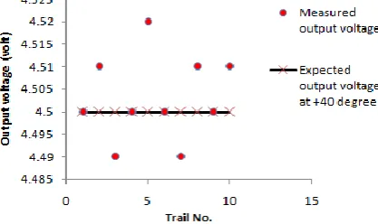
Figure 10.Repeatability test at +40º tilt angel
Figure 11.Repeatability test at -40º tilt angel
The repeteability of that sensing method has been plotted in Fig. 10 & Fig. 11 considering the tilt angel of ±40º at 10 times repeated measurements. It has been evaluated that the repeteability of that measuring method are 0.6%FSO respectively.
V. CONCLUSION
The designed sensor is efficient, in expensive, and multipurpose and produce high resistance to environmental influences. It could be integrated with other primary non electrical sensors and order to get an electrical read out. Immunity to electromagnetic interference is the advantage of this fabricated sensor compared to the resistive [5], capacitive [6] and inductive [7]-[10] type sensing method. In the paper [16] is described the fiber optic inclination sensor with mercury as a movable mass, but with a different principle of operation. The advantage of the presented realization compared to the aforementioned is in using non-toxic materials.
The implemented sensor has exhibits better linearity in extended range of ±50º with an accuracy of 0.8º and resolution of 0.09º also obtained the tilt angel sensitivity of 50mV/º which has realized better sensor characteristics in compared to [14] & [15] at very lower price.
A computer based programming can be used by interfacing this sensor with the DAS card & PC for the purpose of graphical simulation and improvement of non-linearity part in the presented experimental data; it is the future scope of work.
REFERENCES
[1] C. T. Wang, E. H. Yang, J. G. Zhang, Y. X. Ma, and B. Zhang, “The omni-directional electronic level structure and measuring analysis principle,” Journal of Scientific Instrument, vol. 27, no. 2, pp. 183-185, 2006.
[2] J. F. Liu and M. Y. Li, “The principle analytics of gravity sensor level measuring instrument,” Sensors and Instrumentation, vol. 24, no. 7, pp. 159-160, 2008.
[3] H. Weinberg, "Dual axis, low g, fully integrated accelerometers," in Analog Devices, vol. 33, Norwood, MA 02062-9106, U.S.A., pp. 23-26.
[4] S. Fatikow and U. Rembold, Microsystem Technology and Microrobotics, Springer, Berlin, 1997, pp. 226-227.
[5] C. Lin and S. Kuo, “Micro-impedance inclinometer with wide-angle measuring capability and no damping effect,” Sensors and Actuators A: Physical, vol. 143, pp. 113-119, 2008.
[6] D. Benz, T. Botzelmann, and D. Warkentin, “Low cost inclination sensors made from selectively metallized polymer,” Sensors and Actuators A: Physical, vol. 123-124, pp. 18-22, 2005. [7] O. Baltag, “Tilt measurement sensor,” Sensors and Actuators A:
Physical, vol. 81, pp. 336-339, 2000.
[8] B. Ando, “A novel ferro fluidic inclinometer,” IEEE Transactions on Instrumentation and Measurement, vol. 56, pp. 1114-1123, 2007.
[9] B. Ando, A. Ascia, and S. Baglio, “A ferrofluidic inclinometer in the resonant configuration,” IEEE Transactions on Instrumentation and Measurement, vol. 59, pp. 558-564, 2010. [10] L. Rovati and S. Cattini, “Contactless two-axis inclination
measurement system using planar flux-gate sensor,” IEEE Transactions on Instrumentation and Measurement, vol. 59, pp. 1284-1293, 2010.
[11] R. Ragazzoni and S. R. Restaino, “An all-refractive opics for tilt sensing,” Optics Communications, vol. 137, pp. 6-10, 1997. [12] M. Norgia, I. Boniolo, M. Tanelli, S. M. Savaresi, and C. Svelto,
“Optical sensors for real-time measurement of motorcycle tilt angle,” IEEE Transactions on Instrumentation and Measurement, vol. 58, pp. 1640-1649, 2009.
[13] J. H. Wu, K. Y. Horng, S. L. Lin, and R. S. Chang, “A two-axis tilt sensor based on optics,” Measurement Science and Technology, vol. 17, pp. N9-N12, 2006.
[14] H. Bao, X. Dong, C. Zhao, L. Y. Shao, C. C. Chan, and P. Shum, “Temperature-insensitive FBG tilt sensor with a large measurement range,” Optics Communications, vol. 283, pp. 968-970, 2010.
[15] H. Bao, X. Dong, L. Y. Shao, C. L. Zhao, and S. Jin, “Temperature-insensitive 2-D tilt sensor by incorporating fiber Bragg gratings with a hybrid pendulum,” Optics Communications, vol. 283, pp. 5021-5024, 2010.
[16] A. A. A. Aish and M. Rehman, “Development of a low cost optical tilt sensor,” in Proc. 4th International Conference on Autonomous Robots and Agents, vol. 1, 2009, pp. 290-293. [17] T. G. Constandinou and J. Georgiou,
“Micro-Optoelectromechanical tilt sensor,” Hindawi Publishing Corporation Journal of Sensors, Article -ID 782764, pp. 1-7, 2008.
[18] K. Macheiner and F. K. Brunner, “A fiber optic cantilever sensor for static and kinematic tilt determination in two axesk,” in Proc. 4th International Conference on Structural Health Monitoring of Intelligent Infrastructure, Zurich, Switzerland, July 22-24, 2009. [19] D. A. Skoog, D. M. West, F. J. Holler, and S. R. Crouch,
Fundamentals of Analytical Chemistry, 8th ed. India: Thomson, 2007, ch. 24, pp. 718-722.
Subir Das was born in West Bengal, India in 1984. He received Bachelor’s degree in electronics & instrumentation engineering from West Bengal University of Technology, West Bengal, India in 2006 and M.Tech degree in instrumentation & control engineering from University of Calcutta, West Bengal, India in 2010. He is currently an Assistant Professor in Applied Electronics & Instrumentation