ISSN: 2334-2366 (Print), 2334-2374 (Online) Copyright © The Author(s). All Rights Reserved. Published by American Research Institute for Policy Development DOI: 10.15640/jcsit.v3n2a1 URL: http://dx.doi.org/10.15640/jcsit.v3n2a1
Meet the Challenge of Teaching Computer Organization and
Architecture----Physical Computing
Kuodi Jian1
Abstract
Most people agree that the computer organization and architecture is one of the difficult courses in a computer science curriculum. The reason is that a typical Computer Science (CS) student has no hardware background. This paper introduces ways of making the course exciting and engaging by using the concept of physical computing (constructing open source platform computers, offering hands-on in-class exercises).
I. Introduction
Computer organization and architecture is a very important subject. ACM Computing Curricula 2013 treats it as core knowledge to be covered in 16 hours as tier-2 for a CS major. On the other hand, a typical CS student is weak in knowledge about computer hardware and electronics for the fact that computer organization & architecture is the only course that exposes students to the hardware. “Usually, this course is being taught in such an abstract way and at a level away from the wires and computer chips that students have no idea about how computers really work at the hardware level” [1].
In this paper, we introduce ways of engaging students by using the concept of physical computing. Raspberry Pi’s home page defines physical computing as “Computing that involves tangible things connected to a computer, beyond standard input and output devices like keyboards and monitors.
Think buttons, lights, robots, alarms, sensors, home automation, teddy bears called Babbage in near space and so on. We love physical computing because as well as being lots of fun, it's such a powerful teaching and learning tool and encourages creativity, problem solving, and collaboration.“ (Internet resource: Raspberry Pi Foundation. Website: https://www.raspberrypi.org/documentation/usage/gpio/. Retrieved on 9/20/2015) particularly, this paper introduces activities that implement physical computing and make teaching more concrete and engaging. In the rest of the paper, we will introduce pedagogies and activities that contribute to the active learning and the physical computing; we also include the feedbacks from students related to these activities.
Activity 1: Construct the Teaching Tool That Is Open Source Based
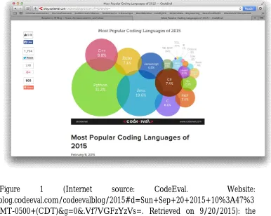
Figure 1 (Internet source: CodeEval. Website: http://blog.codeeval.com/codeevalblog/2015#d=Sun+Sep+20+2015+10%3A47%3 A36+GMT-0500+(CDT)&g=0&.Vf7VGFzYzVs=. Retrieved on 9/20/2015): the popularity rank of computer language.
Figure 2: A homemade Raspberry Pi 2 Model B computer with a camera.
In the following, I will introduce several ways of using this teaching tool.
Using the Teaching Tool to Access GPIO pins
One way of using this teaching tool is to use Raspberry Pi’s general purpose input output (GPIO) pins to control Light Emitting Diodes (LED). The physical computing illustrated here solidifies the concept of memory mapped I/O. The following memory mapped I/O definition is adapted from (Murdocca, 2007, pp 96-97) [2]:
Memory Mapped I/O Definition: when I/O devices are treated like memory locations and ordinary memory read and write commands can be used for reading and writing devices, we call this situation “memory mapped I/O.”
Raspberry Pi uses memory mapped I/O to access its general-purpose input output pins (GPIO). To achieve our objective of active learning, I designed an in-class exercise that can be finished within 15 minutes (this is achieved by giving partial code and asking the students to finish the missing part). To facilitate the flow of information, I let students do the exercise in groups (but each student must turn in his/her own work).
In the following, I will describe how the exercise is set up.
Problem Statement:
Students will be given Raspberry Pi computer with appropriate I/O hardware attached. Also, students will be given partial python code with name “rpGPIO.py” that is located in the directory:
/home/pi/jian/
Currently, the given code has no effect on the red LED (when the checkbox button of the red LED is checked and you click the WriteOut button, the red LED in the hardware will not be turned on. The given code will produce the GUI interface as shown in Figure 3.
Figure 3: GUI interface of Raspberry Pi GPIO tester.
Students’ task is to supply the missing code that is responsible to manage the red LED.
Raspberry Pi GPIO pin Tester
ReadInput WriteOut
GPIO2
GPIO3
GPIO4 GPIO14 x
Required Hardware and Software:
In terms of hardware, besides the Raspberry Pi computer shown in Figure 2, we also need an integrated board (GPIO tester) that has one row of switches, one red LED, and one green LED as shown in Figure 4.
Figure 4: The screen capture of the GPIO tester.
The GPIO pins in the Raspberry Pi have the layout as shown in Figure 5.
The GPIO tester is constructed in the following way:
1. We will use two LEDs as output indicators. The two output pins are GPIO2, and GPIO3.
2. We will use two sliding switches as inputs. The two input pins are GPIO4, and GPIO14. Initially, the pins are pulled up. When the sliding switches are engaged, the pins are forced to ground.
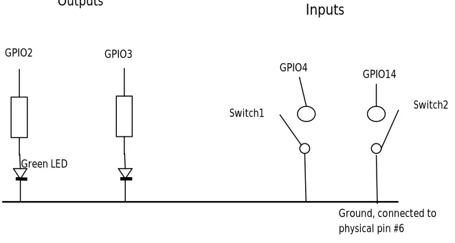
Figure 6 is the schematic diagram of the Raspberry Pi GPIO Tester.
Figure 6: the schematic diagram of GPIO tester.
The following is the physical connections. We will have five lines connected to Raspberry Pi’s I/O pins (please refer to Figure 5):
Ground pin 6 (pin number is the physical number) Switch 1 pin 3
Switch 2 pin 5 Green LED pin 7 Red LED pin 8
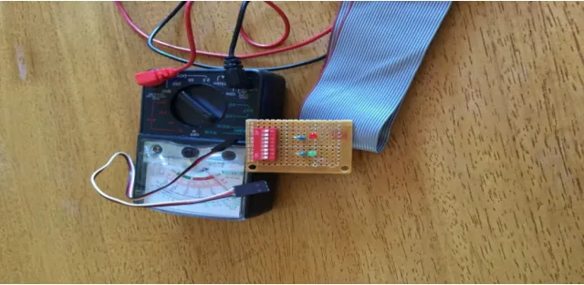
When the GPIO tester is connected to the Raspberry Pi, we will have the hardware (see Figure 7) that is sufficient for the in-class exercise.
Outputs
Switch2 Switch1
GPIO2 GPIO3
GPIO4
GPIO14
Ground, connected to physical pin #6
Inputs
Figure 7: the Raspberry Pi and the GPIO tester.
List 1 is the partial Python code that works with the teaching tool shown in Figure 7. List 1 is given to students to help them get started. As you can see, the code offers the framework of the application and works for most functionalities specified except for the control of the red LED.
List 1: the content of rpGPIO.py (we are using Python version 2.7.8) ======================================== # Access Raspberry Pi's GPIO
importRPi.GPIO as GPIO fromTkinter import *
classRaspberryPiGPIO(Frame):
self.gLED = 2 #BCM naming self.rLED = 3
self.input4 = 4 self.input14 = 14
GPIO.setup(self.gLED, GPIO.OUT) GPIO.setup(self.rLED, GPIO.OUT)
GPIO.setup(self.input4, GPIO.IN, GPIO.PUD_UP) GPIO.setup(self.input14, GPIO.IN, GPIO.PUD_UP) Frame.__init__(self,parent)
self.parent = parent self.initialize()
def initialize(self):
tlb=Label(self,text="Raspberry Pi GPIO pin Tester", font=('Helvetica',20),fg='red')
tlb.grid(row=0,column=0,columnspan=4)
gpio4=Label(self,text="GPIO4") gpio4.grid(row=1,column=0)
gpio14=Label(self,text="GPIO14") gpio14.grid(row=1,column=1)
self.canvas4 = Canvas(self,width=30,height=50)
self.ov4=self.canvas4.create_oval(10,10,25,25,fill='gray') self.canvas4.grid(row=2,column=0,rowspan=2)
self.canvas14 = Canvas(self,width=30,height=50)
self.ov14=self.canvas14.create_oval(10,10,25,25,fill='gray') self.canvas14.grid(row=2,column=1,rowspan=2)
self.canvas2 = Canvas(self,width=30,height=50)
self.ov2=self.canvas2.create_oval(10,10,25,25,fill='green') self.canvas2.grid(row=2,column=2)
self.ov3=self.canvas3.create_oval(10,10,25,25,fill='red') self.canvas3.grid(row=3,column=2)
self.var2 = IntVar()
ck2 = Checkbutton(self,text="GPIO2",variable=self.var2, command=self.processGPIO2)
ck2.grid(row=2,column=3)
self.var3 = IntVar()
ck3 = Checkbutton(self,text="GPIO3", variable=self.var3, command=self.processGPIO3)
ck3.grid(row=3,column=3)
self.btnRead = Button(self,text="ReadInput", command=self.onbtnReadClick)
self.btnRead.grid(row=4,column=0,columnspan=2)
self.btnWrite = Button(self,text="WriteOut", command=self.onbtnWriteClick)
self.btnWrite.grid(row=4,column=2,columnspan=2)
self.pack(fill=BOTH, expand=1)
def processGPIO2(self): if self.var2.get():
self.canvas2.itemconfigure(self.ov2,fill='green') else:
self.canvas2.itemconfigure(self.ov2,fill='gray')
def processGPIO3(self): if self.var3.get():
self.canvas3.itemconfigure(self.ov3,fill='red') else:
self.canvas3.itemconfigure(self.ov3,fill='gray')
defonbtnReadClick(self):
self.canvas4.itemconfigure(self.ov4,fill='gray') else:
self.canvas4.itemconfigure(self.ov4,fill='green')
ifGPIO.input(self.input14) == True:
self.canvas14.itemconfigure(self.ov14,fill='gray') else:
self.canvas14.itemconfigure(self.ov14,fill='green')
defonbtnWriteClick(self): if self.var2.get():
GPIO.output(self.gLED, 1) else:
GPIO.output(self.gLED, 0)
def main(): root=Tk()
root.title("Raspberry Pi GPIO") ex=RaspberryPiGPIO(root) root.geometry("400x250") root.mainloop()
if __name__ == "__main__": main()
============================================
Figure 8: screen capture of a sample run.
Feedbacks From Students
Some feedbacks from the students in my computer organization and architecture course offered in fall 2015 are included in the following:
Student A: “The raspberry pi computer that we worked on in class was in my opinion a great learning tool because of the hands-on nature of studying that it provided us. I was really interested in the makeup of it in terms of its many components and how they were assembled together to make computing something physical and simple to do. Its specs for such a small chip were really amazing and it blew me away because of how complex it was and how simple it was to use. I liked that you could write simple programs on it and I feel like that encouraged me to get my hands on one because I was really interested in trying to write my own simple programs for it.”
Student B: “As far as the raspberry pi and the other boards you put together I can tell you are passionate about your work and that is refreshing to see. The raspberry pi I have worked with on multiple occasions before and I enjoy them but until this class I haven’t written much code for them utilizing the GPIO.
Activity 2: Ask Students To Construct A Raspberry Pi Computer
Another activity of physical computing is to ask students to construct a working computer from scratch. Since not every student has the ability and time to do this assignment, I made it a bonus assignment. To get points, a student needs to bring in the finished computer and to do a demo in front of the class.
To help, I give the following list (List 2) of items, sellers, and their estimated prices:
List 2
============================================
Item price Seller
Sterilitefliptop box (the plastic container) 4.45 spacesavers Raspberry Pi 2 Model B Project Board 43.79 Amazon
7 inch 800*480 HDMI Raspbian LCD 64.99 Amazon (XYG-Study)
Preloaded SD card (8 GB) 11.99 Amazon
Edimax EW Wi-Fi USB Adapter 39.56 Amazon Some small nuts #4-40x3/4” 1.00 Menards Small wood piece (lid holder) 1.00 Home Depot
Small keyboard & mouse 10.00 Amazon
Note: most sellers are the online sellers. You can find them by doing a Google search. Also, sometimes you are able to find kit deal (contains a complete set) which will be cheaper.
Conclusions
In this paper, we presented ways to meet the challenges of teaching computer organization and architecture in colleges and universities. To this end, we introduced activities that implement the concept of active learning and physical computing. The methods and activities introduced in this paper have been taught at the graduate and undergraduate levels and received positive feedbacks from the students. Also, in this paper, we gave our advices on purchasing and constructing the teaching tool that is the centerpiece of this paper. Computer organization and architecture is a rapidly evolving area, and effective teaching is a challenge. We hope that this paper contributed ideas in meeting the challenges of teaching computer organization and architecture at universities and colleges.
References
Jian, K., Constructing a Solid Real-time Operating Systems Course in Computer Science Major, The Journal of Computing Sciences in Colleges, Volume 22, number 4, pp. 65-74, 2007.