Analysis of PI and Fuzzy Controller for DFIG
under Variable Wind Speed Condition
Neeraj Kumar Ram Avtar Jaswal
P.G Scholar Assistant Professor
Department of Electrical Engineering Department of Electrical Engineering
UIET Kurukshetra UIET Kurukshetra
Abstract
Wind power contributes a significant proportion of consumers’ increasing electrical power demands. Due to the current requirements for the expansion of renewable energy as sources of electrical energy, wind energy conversion is getting much interest all over the world. In present scenario the variable speed doubly fed induction generator is the most prolific concept. There are a number of techniques by which we can control grid side and rotor side of DFIG. This paper develops simple doubly Fed Induction generator (DFIG) coupled with wind turbine using PI control and fuzzy logic control. Finally the results of both techniques are compared.
Keywords: Doubly-fed induction generator (DFIG), wind turbine, wind energy, grid side controller (GSC), rotor side controller (RSC), Variable speed wind turbine, PI controller, Vector Control(VC), Fuzzy logic control(FLC)
_______________________________________________________________________________________________________ I. INTRODUCTION
Wind power generation has been growing with pace in the past years and will continue to do so as power electronic technology continues to advance. A number of power converting techniques have been developed for coupling with the electrical grid. The use of power electronic techniques allows for variable speed operation of the wind turbine. A variety of control schemes, varying in cost and complexity, integrated with the power electronic converter has been designed to maximize power output at all possible wind speeds. The wind turbine technology can easily be divided into two categories: the systems without power electronics components, the systems with partially rated power electronics and the systems with full-scale power electronic interfacing wind turbines. First category is the wind turbine systems using induction generators independent of torque in which variation keep an almost fixed speed (variation of 1–2%). The power is limited aerodynamically with use of stall, active stall or by pitch control. The second category is wind turbines having partially rated power converters and much more improved control performance can be obtained.
Wind based power station can work in both the isolated mode as well as grid connected mode. These large wind turbines are based on variable-speed operation with pitch control using a direct driven synchronous generator (without gearbox) or by doubly-fed induction generator (DFIG). Fixed-speed induction generators with stall control are not suitable for these large wind turbines. Doubly-fed induction generators are mainly used by the wind turbine industry for larger wind turbines.
Conventional Proportional Integral (PI) technique based control strategy for DFIG is well accepted in the industry. The intelligent controllers like fuzzy and neural network controllers having much advantages over conventional PI controllers and have been reported in the past. The fuzzy logic control has been successfully applied in DFIG or for a multi machine power system. The converter action determines the operation of a DFIG based wind farm during transient disturbances in a power system. If the PI controllers of the rotor-side converter are tuned properly, it is possible to limit the rotor current and therefore improve the performance of the converter during transient disturbances. Tuning PI controllers are done using traditional methods is computationally. But the tuning of DFIG is quite difficult so now this day’s replaced with artificial intelligent technique. The fuzzy logic approach provides the design of a non-linear, model free controller and hence, can be used for the coordinated control of RSC and GSC in the DFIG system. Also fuzzy not require any mathematical modeling of system so it is easy to implement as compared to PI controller and improve the overall performance of DFIG.
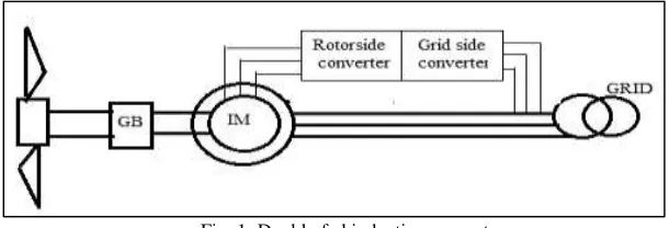
II. DOUBLY FED INDUCTION GENERATOR
Fig. 1: Doubly fed induction generator
Doubly fed induction machine can be operated in generating mode in both at above and below the base speed. The SCIG controlled over a range of sub-synchronous and super-synchronous speeds, using the novel secondary EMF signal generator, shows considerable advantage over sub-synchronous systems based on the Kramer technique [4] and does not have the stability problems associated with doubly fed machines [5].
III. D-Q MODELINGOFDFIG
The general model for wound rotor induction machine is similar to fixed speed induction generator
Stator Voltage Equations:
e d a
q a q a a q a dt d I R
V
(1) q a e d a d a a d a dt d I R
V
(2) Where
qa
V and Vd a= stator voltage of quadrant and direct axis
q aand d a= stator flux of quadrant and direct axis
Ra=stator resistance
Rotor Voltage Equations:
db b e qb qb b qb dt d I R
V
) ( (3) qb b e db db b db dt d I R
V
(
)
(4)
Where
q b
V and Vd b = rotor voltage of quadrant and direct axis
q b
and
d b = rotor flux of quadrant and direct axisRb= rotor resistance
Power Equation: ) ( 2 3 q a q a d a d a
a V I V I
P (5)
) ( 2 3 q a q a d a q a
a V I V I
Q (6)
Where
Paand Qastator active and reactive power
) (
4 3
d a q a q a d a
e I I
T
(7) Torque Equation
Where
T e = electromagnetic torque Flux linkage Equations:
)
( qa qb
m qa la
qa L I L I I
(8)
) ( da db m
da la
da L I L I I
(9)) ( qa qb m
qb lb
qr L I L I I
(10) )
( da db
m qb la
db L I L I I
(11) Where
Lm= magnetizing inductance
Lla AndLlb= stator and rotor leakage inductance
IV. VECTOR CONTROL STRATEGIES FOR DFIG
Performance of DFIG wind turbine depends not only on the type of generator but also on the control strategies executed with different orientation frames. For the doubly fed induction machine in transient state desired amount of reactive power flow into the stator which can controlled by controlling idr and stator active power can be controlled Ps via idr. This can control from both stator side as well as rotor side of reactive and active power with slip power varies. A current systematized pulse with modulation voltage source inverter provides field oriented currents idr and idr to rotor circuit controlling active and reactive power, respectively. The turbine optimal torque speed profile given by active power command same as minimize the machine copper losses command given by reactive power and indirectly torque will be control as given equation. D-q reference frame used to determine by the machine stator flux and currents also field oriented, active and reactive power grid (Pgrid and Qgrid) also controlled. To stabilize the dc bus voltage with Pgrid is controlled through Iqr and to meet the overall reactive power command with Qgrid is controlled through idr. Vector control (VC) gimmick is used for decoupled control of active and reactive power drawn from the supply. Also the VC technique is used for the independent ascendancy of torque and excitation current
Rotor Side Converter Control
The main purpose of controlling rotor side converter is to control stator side active and reactive power independently [7] ,[8]. In order to implement the decoupled control method of active and reactive power, stator flux acclimatized vector control scheme is adopted.
Figure 3 shows the overall vector control scheme of the RSC. In order to accomplish independent control of the stator active power Ps(by modes of speed control) and reactive power Qsby means of rotor current regulation, the spontaneous three-phase rotor currents irabcare sampled and metamorphosed to d-q components idrand iqrin the stator-flux acclimatized reference frame. Subsequently, Qsand Ps(thus the generator rotor speed ωr) can be interpreted as functions of the individual current constituents. Therefore, the reference values of idrand iqrcan be resolved directly from the Qsand ωr adjurations. The actual d-q current signals (idr and iqr) are then correlated with their reference signals (idr* and iqr*) to institute the error signals, which are progressed through two PI controllers to form the voltage signals vdr1 and vqr1. The two voltage signals (vdr1 and vqr1) are compensated by the corresponding cross coupling terms (vdr2 and vqr2) to form the d-q voltage signals vdrand vqr. They are then used by the PWM module to institute the IGBT gate control signals to drive the IGBT converter.
So we can say that by controlling the d- and q-axis component independently of current we can control the stator active and reactive power in decoupled manner.
Grid Side Converter Control
Grid side converter control is used to regulate the voltage across the DC link and sometime also to guerdon harmonics. This is a two stage controller scheme which is achieved by grid voltage oriented vector control scheme i.e. by alienating the dq- axis in the direction of grid voltage [20],[21] and [22].
Fig. 3: Grid side control of DFIG [6]
The main purpose of grid side converter control is done to readjust the DC link voltage. This is done by ceasing grid voltage oriented control scheme. In this paper, the GSC control scheme is also architecture to dispose the reactive power. This might be paramount to keep the voltage within the desired range, when the DFIG vittles into a limp power system without any local reactive compensation. When the DFIG vittles into a athletic power system, the reactive power summons of Qgcan be simply set to zero. Figure shows the overall control scheme of the GSC. The concrete signals of the dc-link voltage and the reactive power (V dcand Qg) are correlated with their commands (Vdc* and Qg*) to form the error signals, which are progressed through the PI controllers to institute the reference signals for the d-axis and q-axis current fixings (idg * and iqg *), respectively. The instantaneous ac-side three-phase current of the GSC are sampled and metamorphosed into d-axis and q-axis current components
idgand iqgby employing the synchronously rotating reference frame mutation. The actual signals (idgand iqg) are then correlated with the corresponding reference signals to form the error signals, which are progressed through two PI controllers. The voltage signals (vdg1 and vqg1) are compensated by the agnate cross coupling terms to form the d-q voltage signals vdgand vqg. They are then used by the PWM module to institute the IGBT gate control signals to drive the IGBT converter.
V. FUZZY LOGIC CONTROLLER FOR DFIG
the derivative of dE/dt of error. These two signals are converted to the respective scale factor and then controller output is given to the vector control block. The figure 3 shows the basic function of fuzzy logic controller [7].
Fig. 4: Basic fuzzy logic controller
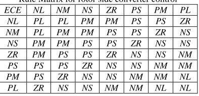
Rule Matrix for Rotor Side Converter Control
Table-1 shows the rule table for the rotor side converter control. The top row and left column of the matrix indicate the fuzzy sets of the variable E and CE respectively and membership function output shown in body of the matrix.
The fuzzy sets are defined as follow: NL= Negative Large, NM= Negative Medium, NS= Negative Small, ZR= Zero, PS= Positive Small, PM= Positive Medium, PL= Positive Large.
Table – 1
Rule Matrix for rotor side converter control ECE NL NM NS ZR PS PM PL
NL PL PL PM PM PS PS ZR NM PL PM PM PS PS ZR NS NS PM PM PS PS ZR NS NS ZR PM PS PS ZR NS NS NM PS PS PS ZR NS NS NM NM PM PS ZR NS NS NM NM NL PL ZR NS NS NM NM NL NL
Rule Matrix for Grid side Converter Control
Table-2 shows the rule table for the rotor side converter control. The top row and left Colum of the matrix indicate the fuzzy sets of the variable E and CE respectively and membership function output shown in body of the matrix.
NB= Negative Big, NVS= Negative very Small NM= Negative Medium, NS= Negative Small, ZR= Zero, PS= Positive Small, PM= Positive Medium, PB= Positive Big.
Table – 2
Rule Matrix for grid side converter control ECE NB NM NS ZR PS PM PB
NB NB NB NB NM NS NVS ZR NM NB NB NM NS NVS ZR PS NS NB NM NS NVS ZR PS PM ZE NB NM NS ZR PS PM PB PS NM NS ZR PS PM PB PB PM NS ZR PS PM PM PB ZR PB ZR PS PM PB PB PB PB
In this paper, the triangular membership function and centroid method of de-fuzzification are used, as these methods are most frequently used in many literatures.
VI. SIMULATION RESULT
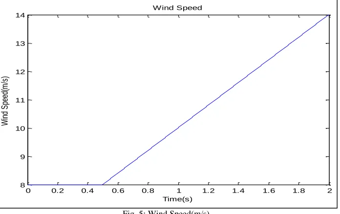
Fig. 5: Wind Speed(m/s)
Fig. VI shows the DC link voltage at variable wind speed, at 0.4 second dc link voltage attain its constant value which is the desired link voltage.
Fig. 6: DC link Voltage
Fig. VII and figure VIII show the inverter side voltage of DFIG with fuzzy logic controller and PI controller respectively. Fuzzy logic controller is giving much better settling time than PI controller. Using fuzzy control inverter side voltage very quickly attains desired value as compared to PI controller.
Fig. 7: Inverter side voltage with fuzzy controller
0 0.2 0.4 0.6 0.8 1 1.2 1.4 1.6 1.8 2
8 9 10 11 12 13 14
Time(s)
W
in
d
S
pe
ed
(m
/s
)
Wind Speed
0 0.2 0.4 0.6 0.8 1 1.2 1.4 1.6 1.8 2
0 100 200 300 400 500 600
Time(s)
V
ol
ta
ge
(V
)
Fig. 8: Inverter side voltage with PI controller
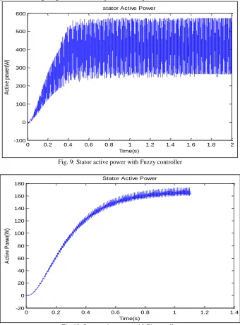
Fig. IX, and X shows the stator active power with fuzzy controller and PI controller respectively. It is clear from the figure that the power curve attains smoothness very fast with fuzzy logic controller as compared to PI controller. It is clear that the settling time with fuzzy controller is giving much better response as compared to PI controller
Fig. 9: Stator active power with Fuzzy controller
Fig. 10: Stator active power with Pi controller
0 0.2 0.4 0.6 0.8 1 1.2 1.4 1.6 1.8 2
-100 0 100 200 300 400 500 600
Time(s)
A
ct
iv
e
po
w
er
(W
)
stator Active Power
0 0.2 0.4 0.6 0.8 1 1.2 1.4
-20 0 20 40 60 80 100 120 140 160 180
Time(s)
A
ct
iv
e
P
ow
er
(W
)
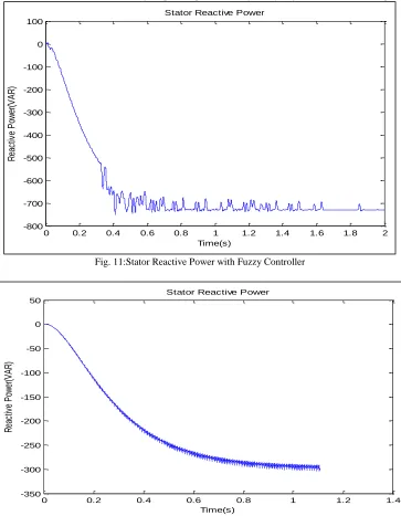
Fig. VII and VIII show the stator reactive power with fuzzy logic controller and with PI controller respectively. Again, in reactive power curve, wave form achieves its settling response quickly using fuzzy logic controller as compared to PI controller.
Fig. 11:Stator Reactive Power with Fuzzy Controller
Fig. 12: Stator Reactive Power with PI controller
VII.CONCLUSION
Fuzzy controllers, in contrast to the conventional PI controllers, can take care of the non-linearity in the control law and hence are known to have better performance than PI under variable operating conditions. In this paper first review the electric equations of the induction machine in the case where the rotor voltage is not equal to zero. After that on basis of these equations a DFIG model is developed, which is compatible with transient analysis. Using fuzzy logic control on this model, independent control of active, reactive power and DC link voltage is possible in simple way. The simulation study made on DFIG and their results show good static and dynamic performance of system with Fuzzy logic controller as compared to PI controller. The simulation results are highly
REFERENCES
[1] S .A. Shaheen, M. A. Hasanien , “Study on Doubly-Fed Induction Generator Control”, MPECON’10,December 19-21,2010,ID 251.
[2] S. Muller, M. Deicke, R.W.D. Donner, “Doubly Fed Induction Generator System for Wind Turbine”, IEEE Industry Application Magazine, May- June, 2002.
0 0.2 0.4 0.6 0.8 1 1.2 1.4 1.6 1.8 2
-800 -700 -600 -500 -400 -300 -200 -100 0 100
Time(s)
R
ea
ct
iv
e
P
ow
er
(V
A
R
)
Stator Reactive Power
0 0.2 0.4 0.6 0.8 1 1.2 1.4
-350 -300 -250 -200 -150 -100 -50 0 50
Time(s)
R
ea
ct
iv
e
P
ow
er
(V
A
R
)
[3] S.Engelhardt, I. Erlish, C. Felter, J. Kretschmann, F.Shewarega, “Reactive Power Capability of Wind turbine Based on Doubly Fed Induction Generator” , IEEE Trans on Energy Conversion, VOl. 26,no.1,pp. 364-372, March 2011.
[4] P. Mitra and G. K. Venayagamoorthy, “Intelligent Coordinated Control of a Wind Farm and Distributed Smart Parks," IEEE Industry Application Society Annual Meeting, Houston, TX, USA, pp. 1-8, October 3 - 7, 2010.
[5] G. K. Venayagamoorthy, “A Successful Interdisciplinary Course on Computational Intelligence”, IEEE Computational Intelligence Magazine – A special issue on Education, Vol. 4, No. 1,pp. 14-23, February 2009.
[6] W. Qiao; G. K. Venayagamoorthy and R. G. Harley, “Design of Optimal PI Controllers for Doubly Fed Induction Generators Driven by Wind Turbines Using Particle Swarm Optimization," International Joint Conference on Neural Networks, Vancouver, BC, Canada, pp. 1982- 987, July 16 -21, 2006. [7] Neeraj Kumar, Ram Avtar Jaswal “Developmaent of Fuzzy Controller for DFIG Connected to Wind Turbine”, International Journal of Electrical and
Electronics Engineering, Print ISSN (P): 2278-9944; ISSN (E): 2278-9952, Volume 5, Number 4, pp. 43-54, June-July 2016.
[8] J.P. Mishra, Debirupa Hore, Asadur Rahman, “Fuzzy Logic Based Improved Active and Reactive Power Control Operation of DFIG for Wind Power Generation”8th International Cconference on Power Electronics, May30- June 3, 2011.
[9] Karim Belmokhtar, Mamadou L. Doumbia, Kodjo agbossou, “Modelling and Fuzzy Control of DFIG based Wind Energy Conversion System”, IEEE, 2012.
![Fig. 2: Rotor side control of DFIG [6]](https://thumb-us.123doks.com/thumbv2/123dok_us/7815312.1663768/3.612.106.508.481.711/fig-rotor-control-dfig.webp)
![Fig. 3: Grid side control of DFIG [6]](https://thumb-us.123doks.com/thumbv2/123dok_us/7815312.1663768/4.612.101.514.240.465/fig-grid-control-dfig.webp)