9
Analysis of Delay in Feedback Power Control
for CDMA Systems
1
L. P. Mishra,
2Mihir N. Mohanty
1,2ITER, SOA University, Bhubaneswar, Odisha, India
Abstract
Transmit diversity techniques have received a lot of attention recently in the area of wireless communication. Closed–loop transmit diversity techniques can provide full diversity and increase the received SNR without space–time coding. The goal of this work is to implement a fast power control algorithm and to evaluate the effect of feedback delay on its performance in CDMA systems. This paper evaluates the effect of delay in feedback power control algorithms on the uplink of code division multiple access
(CDMA) systems. The performance of fixed-step and variable-step
power algorithms are analyzed for CDMA systems. The control mechanism is closed loop one in which the algorithms are based
on the feedback information of signal-to-interference ratio (SIR) measurement at the base station. In ideal conditions, variable-step algorithm outperforms fixed-step algorithm to reduce the effect of Rayleigh fading. It can also track the fading channel accurately
by propertionaly increasing the power control bit. The algorithm
measured uses the measured SIR at every feedback delay and compares it to a given target and adjust the measured SIR to match the target SIR. The performance of the system is evaluated in terms of BER as a function of SIR (Eb/ Io).
Keywords
CDMA, Closed-loop Power Control, SIR, Rayleigh fading, Delay, Step-size parameter.
I. Introduction
Power control is an essential radio resource management method in CDMA cellular communication systems, where co-channel interference is the primary capacity-limiting factor. Power control
aims to control the transmission power levels in such a way that acceptable quality of service for the users is guaranteed with lowest
possible transmission powers. All users benefit from the minimized
interference and the preserved signal qualities. Wireless cellular
communication systems experience a rapid growth during the
last two decades. For achieving these goals is the selection of the multiple access method. Code Division Multiple Access (CDMA)
has been selected as the air interface for these networks. In CDMA
systems the users transmit their signals simultaneously in the same
frequency band. Each user is given a dedicated spreading code,
which is used to identify the users in the receivers by correlating the received signal with a replica of the desired user’s code.
CDMA is interference-limited, i.e. the interference from other users that limits the capacity of the system. To increase capacity, some methods are needed for interference management. Power control (PC) aims to control the transmission powers in such a way that the co-channel interference is minimized, while at the same time achieving sufficient quality of service (QoS). Since in CDMA the users interfere with one another, the co-channel interference
is minimized if minimum possible transmission powers are used.
The problem is then to find the minimum transmission powers such that the QoS requirements of the users are fulfilled. Minimizing
the transmission powers has the additional desirable effect of
prolonging the battery lives of the mobile terminals. The SIR measurement, processing and the transmission of the power control
commands over the air interface constitute a delay between the time the power update command is calculated and the time it is applied in the transmitter. During this time the radio channel and
interference conditions might have changed considerably, which
deteriorates the performance of power control. The closed loop
power control (CLPC) is a sort of “fine tuning” on the open loop power estimate. It should be fast enough to keep up with the fast fading. So, it is the crucial component of any effective scheme
to combat Rayleigh fading.
Many of the power control algorithms proposed in the literature are
studied without taking the loop delay into account [1-5]. However, the loop delay can cause increased oscillations of the SIR around the setpoint, and even make the power control algorithm unstable if it is ignored in the design of the algorithm. Fixed-step power control employs a constant power-updating step size so that
it requires only one control bit to adjust the transmit power at
each power control interval, and hence minimizing the signaling bandwidth. As a result, fixed-step algorithm may not be able to
quickly track the fading channel because it adjusts the transmit
power step by step using a preset constant step size. Variable-step power control algorithm, on the other hand, employs variable step
sizes to allow faster tracking of the channel using multiple control
bits, and therefore it requires higher signaling bandwidth. Some of the researchers have also worked on deay analysis. [6-10] In [7] Kurniwan analyses different system parameter (step size, power-update rate, feedback delay, SIR measurement error, and
command error) on the bit error rate (BER) by using link level
simulation. In [8] a log linear model is studied to analyse the closed loop power control. In [9] a simple procedure for SIR estimation which does not need any complex calibration has been proposed.
Different quantization strategies for the feedback message using
SNR gain as a performance measure have been studied in [10-12].
II. Closed-Loop Power Control
Closed-loop power control aims at eliminating the received signal fluctuation due to small scale propagation loss. In contrast to the large-scale propagation loss, the small-scale propagation loss is uncorrelated between uplink and downlink. Therefore, to control the uplink fading, the uplink channel information must be estimated at the base station and then fed back to the mobile station, so that
the mobile station can adjust its transmit power according to the
fed back information. To obtain the uplink channel information,
the base station can either estimate the received signal strength
or the SIR. In CDMA, however, power control based on SIR is
more suitable than that based on signal strength because CDMA
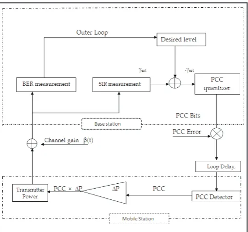
Fig. 1: Model for Closed-loop Power Control
In this model, the signal strength or SIR is first estimated at the
base station for every time slot, Tp, which corresponds to one
power control interval. The estimated quantity is represented by
γest. and is compared with the desired or the target level γt.The
difference between the estimated SIR or signal strength and the
target level is then quantised and sent to the mobile user via the
downlink channel as a binary representation of PCC bits. The command bits are multiplexed with the user data. The mobile users, then extract the PCC bits from the downlink data stream
and use them to adjust their transmit power. Due to the downlink
channel impairments, the PCC bits received by the mobile user can be in error. The PCC bit error is modelled as a multiplicative
quantity with opposite bit polarity. A delay is also introduced by the control loop. This delay is called the feedback loop delay
and is expressed in a multiple, D, of power control interval Tp,
where D is an integer. After the PCC bits are recovered by the mobile user, they are used to adjust the transmit power by the required step size, PCC x Δp. Due to feedback delay, however, the
mobile transmit power (after adjustment) may not compensate the current channel condition because at the time the mobile adjusts
the power, channel conditions may have already changed in a
fading situation.
Closed-loop power control based on measurements on the received signal strength has been studied in [3] while those based on measurements of the SIR appeared in [11]. It is shown in [11] that power control based on SIR appears to perform better than that based on the signal strength. SIR-based power control, however,
has the potential for positive feedback that may occur when the
number of active users exceeds the maximum CDMA system capacity. In this situation, an increase of transmitting power from any user will increase interference to other users, which in turn, are forced to increase their power, and so on.
A. Feedback-Loop Delay
In a closed-loop power control, the effect of feedback loop delay
is an important factor. To overcome the problem due to feedback
delay, power control algorithms may employ a channel predictor.
The loop delay DTp in fig. 1 accounts for the total feedback delay, from the time the channel is estimated by the SIR estimator at
the base station until an appropriate power control command
is received by the mobile and its transmit power is adjusted accordingly. The following factors contribute to the total feedback
loop delay. First, SIR measurement at the base station takes time. Normally, SIR measurement is performed during one time slot and hence, contributes to a one-slot delay. Once SIR measurement is completed, it needs to be compared with the target SIR to generate the PCC bit. Although the processing time at the base station can be negligible, the PCC bit may not be transmitted on the next immediate time slot on the downlink channel, because it
depends on the synchronization between the uplink and downlink
channels. Therefore, the second contributor is the synchronization
delay between uplink and downlink channel. The third contributor
to the loop delay is the propagation time of the PCC bit from the
base station to the mobile (distance dependence). Assuming the
processing time at the mobile to extract the PCC bit from the downlink data-stream may also be negligible, a total feedback delay of 2 slots or more can be expected.
For a Rayleigh fading channel at moderate fading rates, a 2-slot
feedback delay may degrade the power control performance
significantly. This is because the SIR estimates used when the power control command takes place are outdated and do not reflect the most recent power updates because the channel coefficients
change rapidly. The problem of feedback delay has been studied in which a time delay compensation method is proposed to overcome
the problem. In this method the estimated SIR is adjusted according
to the power control commands that have been sent but have not come in effect due to the feedback delay.
III. Power Control Simulation
This section deals with the simulation procedure and system parameters to model the uplink channel of a CDMA system that
employs SIR-based power control. It is assumed that the open loop power control can perfectly overcome the near-far and shadowing problems, so that the average received power is constant and the closed-loop power control algorithm is used only to overcome the fluctuation due to Rayleigh fading. In this case, the dynamic range of power updates in the closed-loop algorithm can be reduced
because the algorithm is only required to track the Rayleigh fading
fluctuation not to track the signal variation due to the near-far
problem.
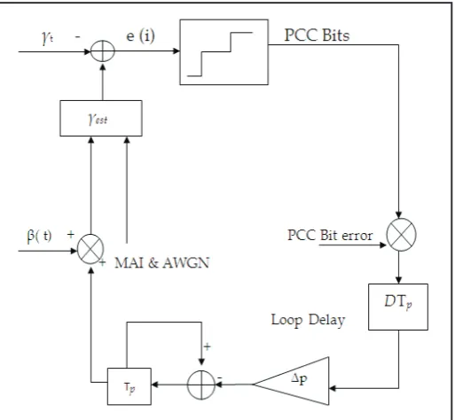
Power control model described in fig. 1 is being used as reference in order to explain the algorithm in more detail here. For power control based on SIR, the mechanism of power control algorithm is shown in fig. 2. The power control algorithm proceeds as
follows.
First, the SIR for each user, γest is estimated at the base station for
the ith time slot. Then the estimated SIR γ
est (i) is compared with
the target SIR γt to produce the error signal e (i). The error signal
e (i) is then quantized using a binary representation, so it can be
transmitted via the downlink channel to the mobile station. The
11
Fig. 2: SIR-based Power Control
The PCC bits are transmitted to a mobile station via the downlink channel. However, the PCC bits are subject to high bit error rates
because they are not coded or interleaved in order to minimize signalling bandwidth on the downlink channel and to avoid the corresponding delays due to the interleaving. The feedback loop
delay, however, is unavoidable. Therefore, transmission of the PCC
bits on the downlink channel suffers from two major impairments:
PCC bit errors and feedback delay. The PCC bit error is represented as a multiplicative disturbance on the PCC bits, while feedback
delay is represented by a delay operator of DTp in the loop as
shown in fig. 2. After the PCC bits are received by a mobile station, the mobile station computes the required power adjustment, Δp x PCC. The step size Δp is preset at 1 or 2 dB, while the PCC is either ±1 in a fixed-step algorithm or any integer between –q and +q in a variable-step algorithm. The integrator over one power control interval, Tp is used to increment the transmit-power level
from the previous level governed by the equation
p (i+1) = p (i) -∆p e ( i-D) q (1)
In the simulation, the system is considered as a single cell CDMA with the number of user K=10. All users are in motion with different
vehicle’s speed to implement a practical situation. To model this
situation, the user speed is made to vary from 5 to 80 km/hr. at 5
km/hr. interval. The system uses the carrier frequency fc = 1.8 GHz
so the users has maximum Doppler spread ranging from 10 to 100 Hz at 10 Hz intervals. The spreading factor M=64 is considered in this simulation. The scheme of modulation is QPSK with a bit
rate Rb = 120 kbps related to the symbol rate Rs = 60 kilo symbol/s in QPSK. In accordance with 3G specification, the power update rate=1. 5 KHz. Therefore the mobile power is updated in each
interval Tp = 0.667 ms. SIR Estimation is performed in every time
slot that corresponds to one power control interval Tp. The chip rate Rc = 3.84 Mcps as given in the 3G standard for uplink data channel. With this chip rate, each time slot contains 2560 chips representing 40 symbols. All symbols in the timeslot are utilized by SIR estimator to estimate the SIR. The AWGN with the noise
variance σn2 = 7 dB below the signal power is added to simulate
the receiver thermal noise. Therefore the composite signals at the
base station consist of all users’ signal and AWGN.
IV. Results and Discussion Simulation 1. Step size=1 dB
The simulation 1 evaluates the effect of feedback delay on the performance of system applied low step size (1 dB). The system is simulated for low speed and higher speed or users whose have the fading rate fD= 50 Hz, and 100 Hz, respectively. From the simulation 1, we can see that the best performance is achieved for low speed user with the fading rate=50 Hz. This because of the power control is updated more frequently. In fading rate=50
Hz, the frequency update power control fDTp= 30 times faster than
fading rate. It is different for fD=100 Hz in which fDTp= 15 times
for fD=100 Hz faster than faster than fading rate.
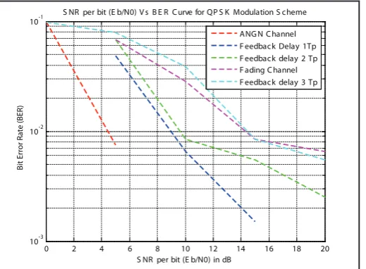
The graph for performance of system with fD= 50 Hz is shown in Fig. 3. In this figure, the best performance is achieved at feedback
delay=1Tp. The better performance is obtained at feedback delay=2Tp. At feedback delay=3Tp, the system almost unable to
perform its performance because the system is close to the fading performance without power control.
0 5 10 15 20 25
10-7 10-6 10-5 10-4 10-3 10-2 10-1
100 S NR per bit (E b/N0) V s B E R Curve for QP S K Modulation S cheme
S NR per bit (E b/N0) in dB
Bit Error Rate (BER)
ANG N Channel F eedback Delay 1Tp F eedback delay 2 Tp F ading Channel F eedback delay 3 Tp
Fig 3 Performance at Step size =1dB, Fading Rate =50Hz
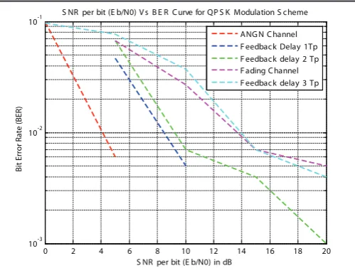
The graphic for the system 1 dB is shown in Fig. 4.This graphic is shown in the performance of the system at fading rate =100Hz. In this case the mobile transmit is updated 15 times faster than fading rate. If frequency update of power control is lower than the fading rate then the fading fluctuation is less able to be tracked.
This situation leads to the degradation of the performance even the performance is close to fading channel.
In Fig 4, the performance at feedback delay=1Tp is slightly better
than the others. The intermediate figure and the top figure are the
performance at feedback delay=2 Tp and 3 Tp, respectively. Due
to the higher fading rates, system with feedback delay=2Tp and
3 Tp at fD =100 Hz is unable to show its performance since the
0 5 10 15 20 25 10-5
10-4 10-3 10-2
10-1 S NR per bit (E b/N0) V s B E R Curve for QP S K Modulation S cheme
S NR per bit (E b/N0) in dB
Bit Error Rate (BER)
ANG N Channel F eedback Delay 1Tp F eedback delay 2 Tp F ading Channel F eedback delay 3 Tp
Fig. 4: Performance at Step size =1dB, Fading Rate =100Hz
In Fig. 5, the performance of 1dB at fading rate fD=150 Hz is
analysed. It shows that the performance with feedback delay=1Tp
is still at the bottom of figure and slightly better than the others.
Due to increased fading rate system performance with feedback delay =3Tp at fd =150 Hz fails to show its performance since
obtained BER are around fading performance.
0 2 4 6 8 10 12 14 16 18 20
10-3 10-2
10-1 S NR per bit (E b/N0) V s B E R Curve for QP S K Modulation S cheme
S NR per bit (E b/N0) in dB
Bit Error Rate (BER)
ANG N Channel F eedback Delay 1Tp F eedback delay 2 Tp F ading Channel F eedback delay 3 Tp
Fig. 5: Performance at Step size =1dB, Fading Rate =150Hz
For all fading rates, the higher the feedback delay, the worse
the performance of power control. This is because the update power that transmitted by the mobile station is out of date and no longer represents the fading condition particularly in higher
feedback delay that resulting in deviation of the SIR from the
target level.
Simulation 2. Step size=2 dB
The simulation 2 evaluates the effect of feedback delay on the
performance of system used step size=2 dB. For all feedback delay,
the best performance is still achieved for low speed user in Fig. 3
with fading rate= 50 Hz. In low speed, the power control is updated
more frequently than the others user with higher speed. For step
size= 2 dB, deep fades at fading rate= 50 Hz can be tracked more
quickly. This will result the better performance at the same fading rate at the system that use the step size=1 dB.
From Fig. 6, it is observed that performance with the fading rate=
50 Hz at feedback delay=1T is better than the performance of
system as result 1 that employed the step size=1dB. Due to higher
step size, it is found that the performance of 2 dB with feedback
delay=2Tp is better than the performance of 1 dB at Eb/Io higher
than 10 dB. For feedback delay=3Tp, the system with the step
size= 2 dB is fail to improve the performance because of higher
feedback delay. In case of 2 dB, the higher feedback delay cause
the performance degraded above the fading performance.
0 5 10 15 20 25
10-5 10-4 10-3 10-2 10-1
100 S NR per bit (E b/N0) V s B E R Curve for QP S K Modulation S cheme
S NR per bit (E b/N0) in dB
Bit Error Rate (BER)
ANG N Channel F eedback Delay 1Tp F eedback delay 2 Tp F ading Channel F eedback delay 3 Tp
Fig. 6: Performance at Step size =2dB, Fading Rate =50Hz
The system performance is analysed at fading rate=100 Hz that shown in Fig. 7 In fading rate=100 Hz, the performance 2 dB
at feedback delay=1Tp is still better than system 1 dB. This is due to higher tracking ability of the system 2 dB. The system at feedback delay=2Tp is similar with the fading performance while at feedback delay=3Tp the system 2 dB is worse than the BER theoretic for fading performance.
0 5 10 15 20 25
10-4 10-3 10-2 10-1
100 S NR per bit (E b/N0) V s B E R Curve for QP S K Modulation S cheme
S NR per bit (E b/N0) in dB
Bit Error Rate (BER) in dB
ANG N Channel F eedback Delay 1Tp F eedback delay 2 Tp F ading Channel F eedback delay 3 Tp
Fig. 7: Performance at Step size =2dB, Fading Rate =100Hz
It is observed that for all fading rates, the BER performance
at system 2 dB with feedback delay=3Tp are worse than the system 1dB and almost worse than the BER theoretic for fading
performance. In other words the system with step size=2 dB is
less applicative at higher feedback delay.
Finally, the analysis for system performance at fading rate=150Hz is shown in Fig. 8. In fading rate=150 Hz, the performance 2 dB
13
at feedback delay =3Tp the system 2 dB is worse than the BER theoretic for fading performance.
0 2 4 6 8 10 12 14 16 18 20
10-3 10-2
10-1 S NR per bit (E b/N0) V s B E R Curve for QP S K Modulation S cheme
S NR per bit (E b/N0) in dB
Bit Error Rate (BER)
ANG N Channel F eedback Delay 1Tp F eedback delay 2 Tp F ading Channel F eedback delay 3 Tp
Fig. 8: Performance at Step size =2dB, Fading Rate =150Hz
V. Conclusion
Feedback delay affects the performance of closed loop power control in CDMA system. The increasing on fading rate will
generate deeper fade that is more difficult to be tracked with small step size. In case of fading rate, we can consider that power
control is not properly work in higher fading rate e.g. fading
rate=100 Hz. The performance is also affected with the design of step size at mobile station. In relation to the step size, we have seen
that the setting of 1 dB is more appropriate for higher feedback delay e.g. feedback delay=3Tp while system of 2dB is more appropriate for lower feedback delay e.g. feedback delay=1Tp.
If the total feedback delay can be minimized e.g. until 1Tp, then the application of 2dB will be better than 1 dB. Conversely, if total feedback delay is difficult to be minimized, then the system of 1 dB is more applicative for higher feedback delay. Therefore,
there is a trade off between step size=1 dB or 2 dB to be created at
mobile station. But from the perspective of efficiency in received power (that correspondence with the capacity), we have found that
the system of 1dB is better than the system of 2 dB at feedback delay =2Tp. In this case, a mobile user can still operate at lower Eb/Io with implies many users can be served at base station. At the end of section, we conclude that the system of1 dB generally is
still better than 2 dB from aspect of delay and capacity. The effect of feedback delay algorithm was analyzed in Rayleigh fading channels. Results show that feedback delay puts strict limits to the applicability of closed–loop algorithms within high mobile speeds while the effect of feedback bit errors is not crucial if a constant bit error rate is assumed. Closed loop power control can
improve the BER performance of slow fading channel. However, power control is not perfect due to feedback delay and finite step size, which produce residual variation of the SIR (power control error). Under ideal conditions, variable step algorithms perform better than fixed step algorithms.
References
[1] C.-C. Lee, R.Steele,“Closed-loop power control in CDMA systems”, IEE Proc.-Commun. Vol. 143, No. 4, pp. 231-239, August 1996.
[2] Lian Zhao, Jon W. Mark,“Multistep Closed-Loop Power Control Using Linear Receivers for DS-CDMA Systems”, IEEE Transactions On Wireless Communications, Vol. 3,
No. 6, pp. 2141-2155, November 2004.
[3] Hsuan-Jung Su, Evaggelos Geraniotis,“Adaptive Closed-Loop Power ControlWith Quantized Feedback and Closed-Loop Filtering”, IEEE Transactions on Wireless Communications, Vol. 1, No. 1, Pp. 76-86, January 2002.
[4] Chockalingam, A., Paul Dietrich, Laurence B. Milstein, Ramesh R. Rao,“Performance of Closed-Loop Power Control in DS-CDMA Cellular Systems”, IEEE Trans. Vehicular
Technology. (to be published).
[5] Andrea Abrardo, David Sennati,“On the Analytical Evaluation of Closed-Loop Power-Control Error Statistics in DS-CDMA Cellular Systems”, IEEE Transactions on Vehicular Technology, Vol. 49, No. 6, pp. 2071-2080, November 2000.
[6] Filyal Fahri, Dwi Astharani,“Feedback Delay Effect on the CDMA Closed loop power control", Second International
Conference on Advances in computing telecommunication
technologies, 2010.
[7] A. Kurniawan,"Predictive Power Control in CDMA Systems", Ph.D Dissertation. Institute for Telecommunication Research,
University of South Australia.
[8] A.Chockalingam, P. Dietrich, L. B. Milstein, R. R. Rao “Performance of Closed-Loop Power Control in DS-CDMA Cellular Systems,” IEEE Trans. Vehicular Technology, Vol. 47, pp. 774-789,
[9] M. L. Sim, E. Gunawan, C. B. Soh, B. N. Soong, “Characteristics of Closed Loop Power Control Algorithm for a Cellular DS/CDMA System,” IEE Proceedings-Communications, Vol. 145, No. 5, pp. 355-362, October 1998 .
[10] A. Narula, M. J. Lopez, M. D. Trott, G. W. Wornell: "Ef£cient use of side information in multiple-antenna data transmission over fading channels”, IEEE Journal of Selected Areas of Comm., Vol. 17, No. 8, Oct. 1998, pp. 1423-1436
[11] J. H¨am¨al¨ainen, R. Wichman,"Closed-loop transmit diversity for FDD WCDMA systems”, 34th Asilomar Conference on Signals, Systems and Computers, October 2000.
[12] J. H¨am¨al¨ainen, R. Wichman,“Feedback schemes for FDD WCDMA systems in multipath environments”, IEEE Vehicular Technology Conference, May 2001.
Dr. Mihir Narayan Mohanty is presently
working as an Associate Professor
in the Department of Electronics
and Communication Engineering, Institute of Technical Education and Research, Siksha ‘O’ Anusandhan University, Bhubaneswar, Odisha. He has published over 150 papers in International/National Journals, Book Chapters, and Conferences along with approximately 25 years of teaching experience in UG and PG level. He is the active member of many professional societies like IEEE, IET, IRED, EMC & EMI Engineers India, ISCA, ACEEE, IAEng etc. Also he is a Fellow of IE (I) and IETE. He has received his M. Tech.
Degree in Communication System Engineering from Sambalpur
O’ Anusandhan University, Bhubaneswar, Odisha. His area of research interests includes – Applied Signal and Image Processing, Digital Signal/Image Processing, Biomedical Signal Processing, Microwave Communication Engineering and Bioinformatics. He has worked as Guest lecturer in many universities. Simultaneously has given many invited talks. He has reviewed many Springer and IEEE based conference papers as well as for some International Journal Papers. Currently four research scholars along with 4 number of PG students are under his guidance on Signal, Image & Speech Processing and Communication Engineering. Some
students are working under his guidance for research work in