IJSRR, 8(2) April. – June., 2019 Page 1107
Research article Available online www.ijsrr.org
ISSN: 2279–0543
International Journal of Scientific Research and Reviews
Design and structural analysis of conventional lathe for retrofitting
Dhruv P. Chokshi
1*, Vijaykumar Chaudhary
21*
PG Student, Mechanical Engineering, C. S. Patel Institute of Technology, CHARUSAT, Anand, Gujarat, India, [email protected]
2
Department of Mechanical Engineering, C. S. Patel Institute of Technology, CHARUSAT, Anand, Gujarat, India, [email protected]
ABSTRACT:
This paper mainly focuses on the design optimization of the lathe machine. Lathe machine is
widely used to manufacture different parts in different types of the material. Static and dynamic
analysis are performed on the main body parts of the machine like base square channel cage table,
casting travel body, tool carriage. These analysis represent that, in both loading condition body can
sustain maximum load with negligible deformation. To improve the design and optimize the design
3D cad model has been designed by using commercial 3D modelling software solid works. And the
3D finite element model has been generated in ansys and analysis also carried out using ansys.
KEY WORDS:
Static analysis, Dynamic analysis, finite element analysis, ansys, design optimization*Corresponding Author Dhruv P. Chokshi
Post Graduate Student,
C. S. Patel Institute of Technology, CHARUSAT,
Anand - 388120, Gujarat, India.
Email: [email protected]
IJSRR, 8(2) April. – June., 2019 Page 1108
1.
INTRODUCTION:
With the prospective of lathe machine, it is only one universal machine that can be used to
develop required parts of another automated lathe. Conventional lathe machine rotate the work piece
and tools are approaches the work piece to chips of the material. Lathes are ideal for the parts which
have round shapes, which can fixed up in the chuck of the spindle of the lathe for operations on it.
Automated lathe have one advanced ability is to drive cutting tool with G- codes and can rotate it
towards Z- axis and also can move the tool post in Y-direction, which is linear motion with respect to
headstock. Automated lathe also have 4 tool carriage system so lathe have to programme for once for
all operations to complete the product cycle.
Due to the automation, conventional lathe machine can quickly shift in to the automated lathe
machine and automated lathe can replace the conventional lathe machine. Automated lathes have
tremendous repeatability with high accuracy and precision up to macro level.
2.
PROBLEM IDENTIFICATION:
During the operational time of the conventional lathe machine there are lots of things which
worker have to handle like, Chuck movement, tool offset centres, jaw attachments, carriage
alignment, tool travel speed, feed rate, drive motor speed, tool changing, linear motion of tool post in
Y axis all this steps etc. to complete their work. Conventional lathe don’t have any feedback system
so machine errors cannot be found easily.1
Major problem of conventional lathe machine are like
Material is not cutting according to requirements.
Lathe is not working properly
Carriage isn’t moving
Accidents
Threads are not being cut properly
3.
MODELLING AND FINITE ELEMENT ANALYSIS OF RETROFIT
LATHE MACHINE:
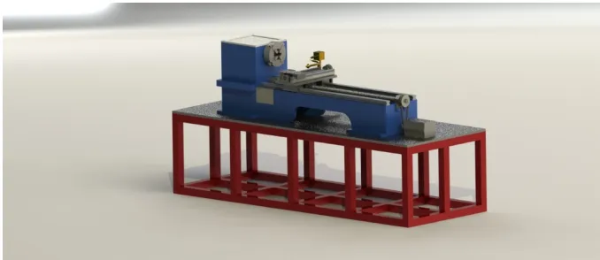
Simplified CAD model retrofit lathe is created by using solid works and it is imported in
ANSYS as a external geometry file. This model shown in below figure.
Major dimensions of the machine are as follow:
Length = 2050 mm
Width = 750mm
IJSRR, 8(2) April. – June., 2019 Page 1109 Height = 1078 mm (total height)
Linear guide way motion area = 950mm
Tool carriage motion length = 350mm
Figure 1 Cad model of retrofitted lathe machine
3.1.
Loading and boundary condition:
Square tube cage table is loaded by static force from the lathe body and work piece load. For the
modal, the maximum loaded weight of the structure is 649 kg. The load is assumed as a uniformed
distributed obtained from the maximum loaded weight divided by the total length of the cage square
Chanel cage.Details of allloading condition of modal is listed down below in table.
There are 4 boundary condition of the model; the first is applied at bottom of the square tube chanel
cage, second boundary condition is applied on the side edges of the square tube chanel cage, third
boundary condition is applied on the top of the square chanel table, like this other bodies have
boundary condition.
3.2.
Applying load:
Load on bottom support table =3500 N (static loading condition)
Load on bottom support table =1500 N (Dynamic loading condition)
Load on bottom cast body =900 N (Static loading condition) Load on bottom cast body =900 N (Dynamic loading condition) Load on carriage =750N (Static loading condition) Load on bottom cast body =750N (Dynamic loading condition) Load on top cast body =200 N.mm moment
3.3.
ELEMENTS AND NODES:
The meshed assembly model has 52376 nodes and 26873 elements. The element is tetrahedral.
In order to get a better results, locally finer meshing applied in the region which have high loading
IJSRR, 8(2) April. – June., 2019 Page 1110
Figure 2 Various loads applied on milling machine bed Table 3: MATERIAL PROPERTIES: Sr.
NO
Material properties Youngs
modulus
Poission ratio
Density
1 Cast iron 1.1×10⁵MPa 0.28 MPa 7.25×10⁻⁶ kg mm-3 2 Aluminium alloy 71000 MPa 0.33 MPa 2.77×10⁻⁶ kg mm-3 3 Structural steel 2×10⁵MPa 0.3 MPa 7.85×10⁻⁶ kg mm-3
4.
RESULTS:
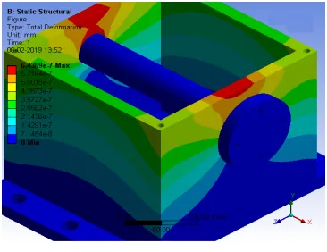
4.1.
Static structure analysis results of the assembly parts:
Figure 3 Total deformation, bottom support frame
Figure 4 Equivalent (von-Mises stress), bottom support frame
Figure 5 Total deformation, top cast body
IJSRR, 8(2) April. – June., 2019 Page 1111
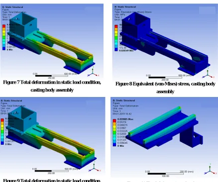
Figure 7 Total deformation in static load condition, casting body assembly
Figure 8 Equivalent (von-Mises) stress, casting body assembly
Figure 9 Total deformation in static load condition, casting body assembly
Figure 10 Total deformation of tool post
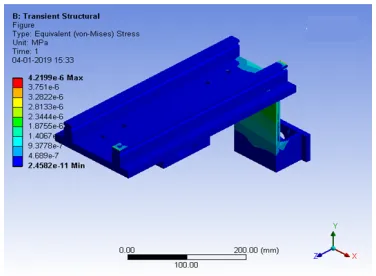
4.2.
Transient structure analysis of the assembly parts:
Figure 11 Dynamic total deformation, bottom support
frame
IJSRR, 8(2) April. – June., 2019 Page 1112
Figure 13 Total deformation, casting body assembly
Figure 14 Equivalent (von-Mises) stress, Casting body assembly
Figure 15 Total deformation, carriage Figure 16 Equivalent (von-Mises) stress
4.3.
Results & discussion:
The results of static structural analysis and transient structure analysis are done with ANSYS and
here weight reduction of the machine is possible. The effect of mass reduction on the static and
dynamic analysis of tool carriage, bottom support frame and bottom cast body discussed in detail.
Table 2: Results of static structure analysis
Sr. NO Part name Total displacement Equivalent (von-mises) stress
Minimum Maximum Minimum Maximum
1 Bottom support frame 0. mm 8.3959×10⁻³ mm 5.7456×10⁻⁵ MPa 2.6986 MPa
2 Top cast body 0. mm 6.4309×10⁻⁷ mm 0. MPa 1.8813×10⁻³ MPa
3 Bottom cast body 0. mm 0.078562 mm 2.8349×10⁻² MPa 2.8349×10⁻² MPa 4 Tool carriage 0. mm 5.9805×10⁻² mm 1.6842×10⁻⁵ MPa 1162.4 MPa
Here in static and dynamic analysis observed that deformation of the bodies are negligible
due to CI cast iron and due to fillet radius at the all corners deformation of the bodies edges also not
IJSRR, 8(2) April. – June., 2019 Page 1113
Table 3: Results of transient structure analysis Sr.
NO
Part name Total displacement Equivalent (von-Mises) stress
Minimum Maximum Minimum Maximum
1 Bottom support frame 0. Mm 1.0756×10⁻⁹ mm 1.4432×10⁻¹² mpa 1.9897×10⁻⁶ mpa 2 Bottom cast body 0. Mm 4.2538×10⁻¹⁰ mm 1.5486×10⁻¹¹ mpa 4.2421×10⁻⁷ mpa 3 Tool carriage 0. Mm 3.9906×10⁻⁸ mm 2.4582×10⁻¹¹ mpa 4.2199×10⁻⁶ mpa
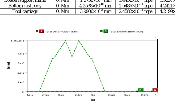
Figure 17 Deformation-Time diagram
1.
CONCLUSION:
The importance of the lathe and milling machine aren’t undetermined if they are
conventional. They are very important in manufacturing world and laid the foundations. But
the modification and new technology must require to improve manufacturing in today’s era.
Here with all analysis and calculation retrofitting can be a good option for advance
manufacturing process.
Reduce machine space area.
Improve the machining process with automated tool post up to macro finishing level.
Reduce the human error with feedback (closed loop) system to improve machine efficiency
and working time.
In terms of manufacturing cost, it may cost around budgetdue to its condition, by means of
that only casting body can be used for retrofitting and these may reduce the cost of the
manufacturing and other all parts must be use new.
2.
FUTURE SCOPE:
IJSRR, 8(2) April. – June., 2019 Page 1114
REFERENCES:
1. Patel, Vijaykumar V., and R. I. Patel. "Structural analysis of a ladder chassis frame." World
Journal of science and Technology 2012; 2(4): 05-08.
2. Tseng, P-C., and J-L. Ho. "A study of high-precision CNC lathe thermal errors and
compensation." The international journal of advanced manufacturing technology 2002;
19(11): 850-858.
3. Wang, Yiqiang, et al. "Field failure database of CNC lathes." International Journal of Quality
& Reliability Management 1999; 16(4): 330-343.
4. Wang, Yiqiang, et al. "A comprehensive reliability allocation method for design of CNC
lathes." Reliability engineering & system safety 2001; 72(3): 247-252.
5. Wang, Chen Sheng, Tjamme Wiegers, and Joris SM Vergeest. "An implementation of
intelligent CNC machine tools." Applied Mechanics and Materials. Trans Tech Publications,
2011; 44
6. Xu, Xun William, and Stephen T. Newman. "Making CNC machine tools more open,
interoperable and intelligent—a review of the technologies." Computers in Industry 2006;
57(2): 141-152.
7. Yeo, S. H. "A multipass optimization strategy for CNC lathe operations." International
journal of production economics 1995; 40(2-3): 209-218.
8. Yun, Won Soo, Soo Kwang Kim, and Dong Woo Cho. "Thermal error analysis for a CNC
lathe feed drive system." International Journal of Machine tools and manufacture 1999;
39(7): 1087-1101.
9. Zhang, Gen Bao, Lian Zhang, and Yan Ran. "Reliability and failure analysis of CNC
machine based on element action." Applied Mechanics and Materials.Trans Tech
Publications, 2014; 494
10.Zhang, Jun, et al. "Research on the dynamics of ball screw feed system with high
acceleration." International Journal of Machine Tools and Manufacture 2016; 111: 9-16.
11.Zhu, Wen-Hong, Martin B. Jun, and Yusuf Altintas. "A fast tool servo design for precision
turning of shafts on conventional CNC lathes." International Journal of Machine Tools and