ISSN: 2231-5381 http://www.ijettjournal.org Page 52
Effect of Amorphous Layer on the
Microstructure and Properties of Al-B
4
C
Layered Composite
Paulo A. Inacio*1,Yubo Zhang *#2,Jinchuan.Jie*3, Tingju. Li*4
*Key Laboratory of Solidification Control and Digital Preparation Technology (Liaoning Province), School of Materials Science and Engineering, Dalian University of Technology, Dalian 116024, China
#
State Key Laboratory of Metal Material for Marine Equipment and Application, Anshan, 114000,China
Abstract - An Al-Al+B4C-Al layered composite was
produced by semi-continuous casting and hot rolling method, the innerlayer is Almatrix reinforced by 40wt.% B4C (F60), while the outlayer is pure Al. The
result shows that the composite innerlayer (Al-B4C)
has a high macrohardness of 43HBS1.5/125/30, once the outlayer pure Al has 16.5HBS1.5/125/30. However, due to the significant difference between Al and B4C in the inner layer, there are always defects
near their interface and there is a sharp hardness gradient. By means of surface alloying, oxidation and acid attack on the reinforcement surface, a microamorphous transition (MAT) layer was found bounding the reinforcement’s particles. The microhardness behaviour shows the MATlayer has ~900HV (1Kgf/15s) on the reinforcement boundary and decays exponentially until the transition layer have no effect on the Almatrix (~32HV). This MAT layer bounding the reinforcement reduces the properties gradient and raises the composability, leading to a better impact resistance.
Keywords: B4C, layered composite, Amorphous
Layer, Reinforcementtreatment.
I. INTRODUCTION
Aluminum metal matrix composites (AlMMC also called AMC) consists of at least one metal and a reinforcement material,suchas fiber, particles, compounds, oxides, carbide etc., in order to achieve the requirements and expected properties which cannot be met by single compound materials [1]-[4]. Though designing an optimized structure, AMC can achieve better performance. For example,by mixing Alalloy and B4C powers together we can obtain a
light and hard composite. Boron carbide (B4C) has a
high melting point, outstanding hardness, good mechanical properties, low specific weight, and great resistance to chemicals [5]-[12]. On the other hand, Al alloys have low density, low cost, and good properties [13].
A threelayered (soft-hard-soft) composite is proposed to take full advantage of each material, consisting of pure Al outlayers and a B4Creinforcement Almatrix as core (inner layer).
Such composite can combine the core high hardness
of B4C particlereinforced and the outer layer
weldability and toughness.
Composites with reinforcementssize up to 100 mesh and high wt.% are desired to shielding and protective armour applications, also has applications as abrasive material and proton absorption. However, the addition of large size reinforcements alsointroduces some defects, such as brittleness elevation, high unbound ratio and big properties gradient on reinforcementmatrix interface [13]-[14]. In addition, the recommended balance of the ceramic reinforcements in AMCs is less than 20 wt.%, when this value is exceeded the AMC significantly increases their brittleness, but by reducing the reinforcement content it reduces the hardness range and it no longer meets the high hardness requirements. Thus, a lot of work is needed to manufacture a worthwhileAMC with large reinforcement size and high wt.%,simultaneously.
In general, many routes can produce AMC; one of those is the powder metallurgy (PM) by blending elemental or prealloyed powders together. However, it is uneconomical to industrial production and the products of metallurgy can have limited shapes and features, which limit its wide application. On the other hand, the casting method can achieve efficient production and low cost. However, some problems as particle agglomeration and low interface interaction between B4C and Al need to be resolved[14]. In our
previous study, a semi-continuous casting followed by a hot rolling process were designed to fabricate a threelayered composite material consisting of an Al outer layer and a 7075-B4C inner layer.
In the present work, by means of metal addition, oxidation and surface acid attack (SAA) a microamorphous transition (MAT) layer was made bounding the surface of B4C (F60) in order to counter
large size and high content disadvantages such as: high gradient properties between the hard reinforcement and ductile matrix, reinforcement surface defects and low Al-B4C interface reactivity.
ISSN: 2231-5381 http://www.ijettjournal.org Page 53
II. EXPERIMENTAL PROCEDURES
For the final composite acquisition, two main steps are required:
A. Reinforcementtreatment
The first step aims to oxidize the reinforcement surface flaws and inlay some substrate to promote the formation of theMAT layer. The nickel has high interface affinity with B4C and Al as was
investigated[18]-[20], leading to the utilization of this metal.The amount of 5wt.% thin Ni(99.99%) is mixed with B4C, the powder is placed into a rotary
drum mixer at 3.14 rad/s for 120 min. The peak of oxidation in humid air that doesn’t compromise the whole reinforcement properties is deeply investigated [10]-[11], [21]-[23] and a common denominator is found around1173K for 120 minutes.
The B4C powder nominal size of 60meshis used,
the size distribution of which is a compound normal distribution, i.e., the size of 90% the B4C is in the
range of 250-350 μm.The furnace actual sensor reliability is ±20K. The full process can be resumed in the Fig. 1.
The samples stirs for 5 minutes every 30 minutes in the furnace to ensure a better nickel adhesion (inlaid) on the B4C surface. With graphite crucible
and stick aiming to reduce the contamination. The reinforcementpowders are analysed by laser scanning microscope (LSM),Raman spectroscopy (DRX), Infrared spectroscopy (FTIR) and X-ray powder diffraction (XRD).
On the second step, aSAA of 0.1 ml/gHSO3Cl/B4C(oxidized)is made. The HSO3Cl
self-decompound in H2SO4 and HCl, the two main
acids that strongly react with oxides and decompound ceramics [24]. The HSO3Cl (99.00%) is carried out
under chemical fume hood due to acid hazardswith agitation for 10 minutes. The samples are then washed in abundance with hot water at 363K, filtered and dried at 373K for 60 minutes.
B. Semi-continuous casting and hot rolling The Compositeis produced by a simplified semi-continuous casting method and hot rolling. The outer layer of the composite is constituted by Al (99.70%).The AMC innerlayerpowder is constituted by Al(99.85%) and B4C (as treated) powders in a
ratio of 40wt.% (few samples with 10wt.%astreated/untreated and 40wt.% untreated are made to comparison). The powder isplaced into a rotary drum mixer at 3.14 rad/s for 120 min. The casting method was designed based on previous work made by Xu et al. [1]as shown in Fig. 2. The mixed powders were placed in a stainlesssteel mould (dividing plate) supported by Al sheets (up and down sides). The molten Al (1023K) was poured into the stain steel mould to form a solidified Al shell.During the casting process, the stainlesssteel dividing plate was elevated and the mixed powders gradually contacted with the liquid Al. After molten Al reaches the top of the mould, the composite is left to cool
down at room temperature (~288K) and is then unmoulded.
Fig.1Composite acquisition diagram
After the casting process, the ingot is placed in an electric box resistance furnace at 723±10K, this temperature improves the density of the composites and the bond between layers [25]. The rolling direction is unidirectional with the same direction of “Pull out direction” marked in Fig.2.The hot rolling process reduces the crosssection thickness from 75mm to 15mm, with 20 passes, it means a rolling reduction of 4% per pass, corresponding to a final reduction of 80%.
For microstructural examination, the composite samples were cut into smallpieces (cross section 20 mm × 15 mm) by line cutting, and then polished. To investigate the microstructure,alaser scanningmicroscope (LSM), an electron micro probe analyzer (EMPA) is used. The macro hardness test HBS1.5/125/30was carried out at room temperature (~293K) using a Digital Brinell Hardness Tester MHB-3000.The micro hardness test ISO 6507-1 (1Kgf/15 seconds) is carried out in the Digital Vickers Hardness Tester machine. Impact toughness test samples were cut in 15x10 mm crosssection with 100 mm length. The test was performed 3 times for each group along the transversal direction, the test energy was 150J.
Fig.2 Semi-continuous casting method used to ingot acquisition
III. RESULTS AND DISCUSSION
A. Surface treatment
The B4C oxidation must have a vitreous layer,
ISSN: 2231-5381 http://www.ijettjournal.org Page 54
shows strong color change and surface flawsreduction, such fact is explained by the oxide formation overlapping the entire reinforcement surface with acrystal-glass oxide layer. The main oxidation reaction produces B2O3 (glass/crystal) and
CO2 and secondary reactions in humid air
alsoproduces others boron and carbon compounds (H3BO3, CO, etc.) [21]-[23].
The surface transformation is explained by Fig. 3, where (a)is the original B4C surface, (b) is the B4
C-Ni(oxidized) reinforcement and (c) is the SSA given surface.
Fig. 3 Macrostructure ofB4C-5 wt.%
Nisurfacesobservedby LSM, (a) untreated, (b) Oxidized and (c) As treated surface
The Niadhesion is observed by metalliccolor spots. In Fig.3(c) the principal flaws are not visible anymore and the whole surface is more “regular’ and “flat” than the original surface present inFig.3(a), some degree of “etching” also is observed. Such analysisdemonstrates the oxidelayer formed at this temperature and time is enough to oxidize the superficial imperfections and then the SAA is able to remove them in a macro scale [26]-[27].
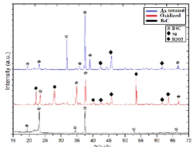
The LSM only showsvisually the reinforcement surface. To understand the compounds yielded and bounds in the reinforcement surface,the XRD is performed. The XRD patterns of the samples aregiven in Fig.4. Metallic Ni and borates seem to be the dominant phase in the oxidized sample. However, no catalyzing effect of Ni was observedat 1173K. Comparing the XRD(Fig. 4), the as treated andoxidized sample, somepeaks attributed to B oxides as B2O3are not present in SAA sample,
meaning it has removed or it remains in an undetectable amount [28]-[31].
Fig.4 XRD patternsofB4C-5 wt.% Ni forastreated,
oxidizedanduntreatedpowder samples
In order to study clearly the bonds on reinforcement surface, the Raman and infrared analysis provide good information.
Fig. 5 Raman spectroscopy ofB4C-5 wt.% Nifor
astreatedand oxidized powder samples
The Raman spectroscopy (Fig. 5) shows a typical carbon D and G bands. The D and G bands intensity ratio put this carbon as a glassy or cluster carbon on the surface. The D band has a peak around 1350 cm-1 which is attributed to carbon sp2 carbon bonds. The G band is not clear about its source and this issue generates a lot of discussion amongst researchers, havingdifferent attributions according to different references.
The peak around 1580 cm-1does not seem to be aspectrum of boron carbide.This peak ispresent in the Raman spectra of carbonrich boron carbides as well, and in this composition range the existence of free carbon in boron carbide may can be excluded. This peak can be ascertained that at any carbon content in carbonrich B4C considerable concentration of C-B-B
ISSN: 2231-5381 http://www.ijettjournal.org Page 55
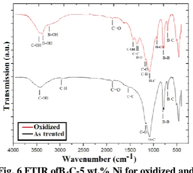
Fig. 6 FTIR ofB4C-5 wt.% Ni for oxidized and
astreated powder samples
TheFTIRof theoxidized powder bands shows elementsaround 3485cm−1(C-OH), 3265cm−1(B-OH), 1462cm−1 (B-OH),1395cm−1(C-OH), 1249 cm−1 (B-O),1188cm−1 (C-O)corresponded to boron carbon oxides. The result also confirms that boron oxide ismainly removed from the B4C surface through SAA
due to (B-O) bounds reduction. The band at 2368 cm−1ascribed to free carbon is not found in any analysis in accordance to the Raman analysispossible excluding the free carbon preposition[34].
The chemical bonding of the SAA B4C powder
that has a strongest vibration around 1079cm−1(B-C) can be attributed to the characteristic inter icosahedral B4C vibration. The boron oxide in as
treated powder probably originated from incomplete oxides removal or it is a contaminant. The peaks around 837cm−1 and 605cm−1are also in agreement with the reported typical B4C vibration band.The
weak peak about 1188cm−1 should be assigned to (C-O). The broad band at 3485cm−1 was attributed to the (O-H) vibration. The peak around 2900cm−1is ascribed to the (C-H) band, which may represent one contaminate.
The conclusion that can be abstracted from the XRD, Raman and FTIR analysis are; The boron oxides are mainly removed, but possibly have some residues. carbon oxides are probably in gas phase and released out to the atmosphere, but free carbon may be present in crystal-glassy phase. Ni is truly inlaid to the reinforcement surface and it has no catalyst effect, peradventure it can yield to some interactions with carbon, boron and oxygen, despite Nibounds are not
in strong intensity in the analyses [35]. Some contaminations as water are present in as treated reinforcement. After those analysis, the reinforcement shows the desired properties; a regular surface with nickel inlaid, a surface with low oxides concentration and probably a surface with high carbon bounds disorder.
B. AMC Inner layer microstructure
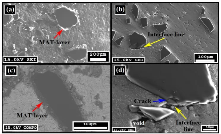
The microstructure analysis of the composite inner layer shows a visible MAT layer bounders the reinforcementsas shown in Fig.6(a) and 6(b) by different technics.Thislayer ispossibly composed of intermetallic particles as Ni3Al, or Ni-Alrich particles
ISSN: 2231-5381 http://www.ijettjournal.org Page 56
C. AMC Micro and Macro PropertiesThe micro hardness tested from a point on transition layer immediately after B4C and MATlayer
interface going towards the matrix shows some similarity with an exponential decay function Equation (1). This fact may demonstrate the correlation to bulk diffusion and MATlayer formation. Although it is related withdiffusion, for amorphous materials, the stoichiometric formula is undefined andsome constants on Arrhenius diffusion equation cannot be explicit.Based on the decay function, the following similarity can be made with the followingconditions:
𝑃𝑥= 𝑝∞+ 𝑝0𝑒−𝛿𝑥(1)
Where, Pxis a property (hardness, density, etc.),
𝑝∞ is the matrix properties considering itis homogeneous,(r0) is the average reinforcement radius
(approaching it as circumferential),P0= P(0) is the
initial quantity atx=r0, andγisempirical value related
to the decay rate.For such approximation to be valid some conditions must be taken; Assume the distance
(x) is always greater than (r0). Experimentally for (x)
greater than 10r0 the radius can be considered infinite
and only the matrix propertiestakes effect.This conclusion is showed in Fig.7.
To manipulate the gradient intensity for the matrix micro hardness, the average distance between the reinforcements is needed and it can be found by the relation in equation (2) [1]. Using as input data only the volumetric fractions of each component and the reinforcement average radius, the prediction of the matrix average hardness is done when𝑥 = λ is introduced in the Equation (1) from relation (2).
𝜆 =4 1−𝑓 𝑟0
3𝑓 (2)
Where λ is the distance between the reinforcements, f
is the reinforcement fractional volume. The experimental and calculated micro hardness data are plotted in Fig. 7 using empirical δ.
Fig. 7 The micro hardness test (HV)of composites made by astreated and untreated powders
To measure the macro theoretical properties, the following relation can be used [14].
𝐸𝑐= 𝐸𝑚𝑉𝑚+ 𝐾𝑐𝐸𝑟𝑉𝑟(3)
Where, Kc is an experimental constant between 0 and 1. This range of values for Kc reflects that the particle reinforced composites are not characterized by the iso-straincondition,E is the property to be evaluated, V is the mass fraction. The subscripts c, m, rrefers to composite, matrix, and reinforcement, respectively. The Brinell hardness test is demonstrated in Fig. 8(a). The tested samples are demonstrated in Fig. 8(b).
The sample with 40 wt.% B4C untreated
demonstrates poor results cracking under the test load as show in Fig.8(c).Admit the macro hardness as “E” property in the relation (3).
ISSN: 2231-5381 http://www.ijettjournal.org Page 57
Fig. 8 The Brinell hardness test HBS1.5/125/30 of Al and composites made by untreated and
astreated powder
Abstracting the data from the experimental plot (Fig. 8) it is possible to calculate the empirical values of Kc. To the sample 10wt.%B4C untreated the Kc is
0.0710 and to 40wt.% as treatedthe Kcis 0.0344, it clearly shows the effect of adding large amounts of reinforcement modifies the final composite properties.Abstracting data from experiments made under similar circumstances (40wt.%B4C main size
23µm, without MAT layer)it demonstrates Kc equals to 0.03477, and for 40wt.%B4C main size 70µm [1]
the Kc is 0.0277. Assuming Kc linear the expected value to 60 mesh is 40% less than one with MAT layer.
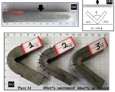
Fig. 9 Impact toughness response of Al and composites made by untreated and astreated
powder
The problem in any composite with large relative reinforcements size are thedefects as cracks on the interface making it very fragile, failing catastrophically under low loan. Fig. 9 demonstrates the impact toughness test.The pure Alsample has anabsenceof fractures due to its own ductility. To the sample 40wt.%B4C untreated, the brittle fracture in
the innerlayer is quite visible showing the facility to the cracks propagation. To the last sample 40wt.% B4C as treated, one macro crack is noted, and that
crack leads the composite to failure.Despite the failure, the quantity of macro cracks is extremely lower than a same composite without surface treatmentandMATlayer. One more way to quantify the difference between the composites is by analyzing the deformation angle ɸformed after the
impact, once it has not cracked under test load. The tested samples angles are ɸ1=57o, ɸ2=56o and ɸ3=71o
(±5o), the bigger angle in the sample astreated shows the innerlayer contribution to the composite toughness. However the low value on theuntreated sampleis almostthe same as the pure aluminum expresses in this case the innerlayer does not have a significant influence due to composite toughness [36]-[37].
IV. CONCLUSION
The Al-Al+B4C-Al layered composites were
produced by semi-continuouscasting method and hot rolling, the microstructure and mechanical properties were evaluated. From the study, the following conclusions can be abstracted:
• The B4C powders are successfully oxidized and the
SAA removes surface oxides and imperfections. • The MATlayer was formed and it isbeneficial to the layered AMC mechanical properties.
•Improving the reinforcement surface and inserting a MAT layer raises the composite mechanical properties allowing the utilization of high reinforcement size and wt.% in composites innerlayer to engineering applications.
ACKNOWLEDGMENTS
This research was supported by a Dalian University of Technology, Laboratory of Special Processing of Raw Materials and School of Material Science and Engineering, Dalian University of Technology, Dalian, Liaoning 116024, China.
REFERENCES
[1] G. Y. Xu, Y. H. Yu, Y. B. Zhang, T. J Li, T. M. Wang. “Effect of B4C particle size on the mechanical properties of B4C reinforced aluminum matrix layered composite”. SECM, v. 26, Issue 1, p. 53-61.
[2] Y.Z. Li, Q.Z. Wang, W.G. Wang, B.L. Xiao, Z.Y. Ma, “Effect of interfacial reaction on age-hardening ability of B4C/6061Al composites”, Materials Science and Engineering A 620, pp. 445-453.
[3] Vikrant Chandel, Onkar Singh Bhatia "Fabrication and Characterization of Al 7075-Cenosphere Composite & its comparison with pure Al 7075", International Journal of Engineering Trends and Technology (IJETT), V29(3), pp. 133-142 Nov. 2015.
[4] Y. B. Zhang, Y. H. Yu, G. Y. Xu, Y. Fu, T. J. Li, T. G. Wang, Q. T. Guo, “Microstructure and Performance of a Three-Layered Al/7075–B4C/Al Composite Prepared by Semi Continuous Casting and Hot Rolling”,Metallurgy Journal 8(8):600. 2017.
[5] F. Thévenot. “Boron Carbide A Comprehensive Review”. J. Eur. Ceram. Soc 6, pp. 205-225, 1990.
[6] N. K. Shrestha, M. Kawai, T.Saji. “Co-deposition of B4C particles and nickel under the influence of a redox-active surfactant and anti-wear property of the coatings”. Surface & Coatings Tech. pp.2414-2419, 2005.
[7] A. Ektarawong, S.I. Simak, L Hultman, J. Birch,B. Alling. “First-principles study of configurational disorder in B4C using a superatom-special quasirandom structure method”.Physical Review B, Vol. 90, Issue 2, July. 2014. [8] J. H. Wang, Y. He, Z. F. Xie, C. L. Chen, Q. B. Yang, C.L
ISSN: 2231-5381 http://www.ijettjournal.org Page 58
anticorrosion performance of epoxy resin”, Polymers Adv. Technologies, pp. 758-766, Feb. 2018.
[9] I. Topcua, H.O. Gulsoyb, N. Kadiogluc, A.N. Gulluoglua. “Processing and mechanical properties of B4C reinforced Al matrix composites”. Journal of Alloys and Compounds, 482,pp. 516-521, 2009.
[10] R. Telle. “Oxidation behavior of B4C-SiC composites with various microstructures”. AIP Conference Proceedings, 1991, 231, p. 553.
[11] L. M. Litz, R. A. Mercuri. “Oxidation of Boron Carbide by Air, Water, and Air-Water Mixtures at Elevated Temperatures”.Journal of The Electrochemical Society 110(8), Jan. 1963.
[12] D. M. Bylander, L. Kleinman, S. B. Lee. Self-consistent calculations of the energy bands and bonding properties of B12C3. Phys. Rev. B42, 1990.
[13] E. Ghasali, M. Alizadeh, T. Ebadzadeh, A.H. Pakseresht, A. Rahbari. Investigation on microstructural and mechanical properties of B4C-aluminum matrix composites prepared by microwave sintering. J Mater Res Technol;4(4), p. 411-415, 2015.
[14] H.Courtney, Thomas. Mechanical behavior of materials.2nd ed,Boston: McGraw Hill. 2000.
[15] D. M. Scruggs, “Composite material bonded by an amorphous metal, and preparation thereof”,United States patent,US4621031A, August, 01,1994.
[16] L. F. Bailey, R. J. Bennett, “DICOR® Surface Treatments for Enhanced Bonding,Journal of Dental Research 67(6), p. 925-3, Jul, 1988.
[17] V. A. Lavrenko, A. P. Pomytkin, P. S. Kislyj, B. L. Grabchuk, “Kinetics of High-Temperature Oxidationof Boron Carbide in Oxygen”, Oxidation of Metals, Vol. 10, No. 2, 1976.
[18] C.W. San Marchi. “Processing of Aluminum-Nickel Amorphous by Reactive Infiltration”, PHD Eng. thesis,MIT, USA, 1997.
[19] (2018) AZoN, Scientists Develop Nickel Aluminide Composite Material that Can Cut Through Cast Iron and
Granite, [Online]. Available:
https://www.azom.com/news.aspx?newsID=3866
[20] B. K. Ozcelik, C. Ergun, “Effect of Ni on The Synthesize
Boron Carbide Via Aerosol Method”,
Researchgate.RG.2.1.4392.1765, July 2015.
[21] H. Shmue. “Reaction-bonded boron carbide for lightweight armor: The interrelationship between processing, microstructure, and mechanical properties”,American Ceramic Society Bulletin, Vol. 96, No. 6 pp. 20-26, August 2007.
[22] A. Kilicarslan, F. Toptan, I. Kerti, S. Piskin, “Oxidation of boron carbide particles at low temperatures”,Mat. Letters, 128(1), pp. 224-226, 2014.
[23] Y.Q. Li, T. Qiu, “Oxidation behaviour of boron carbide powder”, Materials Science and EngineeringA 444, pp. 184-191, 2007.
[24] (2018) NIH U.S. Compound Summary for CID 24638.
Chlorosulfonic acid. [Online] available :
https://pubchem.ncbi.nlm.nih.gov/compound/Chlorosulfuric _acid#section=Top.
[25] Redankamma Yenumula, Srinivasulu Dorasila, CV Ramana Murthy Naidu S, Rambabu Kalpukuri, "Experimental Investigation of Mechanical Properties of Pure Al-Sic Metal Matrix Composite by Stir Casting Method", International Journal of Engineering Trends and Technology (IJETT), V59(3),148-154 May 2018.
[26] M. Kern, Vol. P. Thompson, “Bonding to glass infiltrated alumina ceramic: Adhesive methods and their durability”,
The Journal of Prosthetic Dentistry,73(3):240-9, Mar, 2005. [27] Y. Chaiyabutr, S. Mcgowan, K. M. Phillips, J. C. Kois, R. A.
Giordano, “The effect of hydrofluoric acid surface treatment and bond strength of a zirconia veneering ceramic”, The Journal of Prosthetic Dentistry Vol. 100, Issue 3, Sept. 2008, p. 194-202.
[28] Mike Glazer, International Tables for Crystallography. International Union of Crystallography, Vol. A, ch. 2.3, pp. 193-687, 2006.
[29] J. A. Bigdeloo, And A. M. Hadian, “Synthesis of High Purity Micron Size Boron Carbide Powder from B2O3/C Precursor”, International Journal of Recent Trends in Engineering, Vol. 1, No. 5, May 2009.
[30] I.A. Rakhmatullin, A.A. Sivkov, A.F. Makarova, “Boron carbide nanopowder synthesized using electrical discharge plasma”, Journal of Physics, Conference Series 552, 012008, 2014.
[31] H. Saitoh, K. Yoshida, W. A. Yarbrougha. “Crystal structure of new composition boron-rich boron nitride using Raman spectroscopy”. J. Mater. Res., Vol. 8, No. 1, Jan 1993.
[32] D. R. Tallant, T. L. Aselage, A. N. Campbell, and D.
Emin.“Boron carbide structure by Raman
spectroscopy”,Phys. Rev. B 40, p. 5649, 1989.
[33] D. R. Tallant, T. L. Aselage, and D. Emin, “Structure of icosahedral borides by Raman spectroscopy”, AIP Conference Proceedings231, p. 301, 1991.
[34] K. I. Sasaki, Y. Tokura , T. Sogawa.“The Origin of Raman D Band: Bonding and Antibonding Orbitals in Graphene”, Crystals, Vol. 3, pp. 120-140, 2013.
[35] F. Davar, Z. Fereshteh, M. Salavati-Niasari, “Nanoparticles Ni and NiO: Synthesis, characterization and magnetic properties”, Journal of Alloys and Compounds 476, pp. 797-801, 2009.
[36] B. Raj, K. Bhanu, S. Rao,Mechanical Testing: Overview, Encyclopedia of Materials: Science and Technology, 2001. [37] F. Ouchterlony,Fracture Toughness Testing of Rock.