Themed Section: Science and Technology
Extenuation of Voltage Variations and Load Leveling in Wind-DG
Microgrid with Back Propagation using ANFIS Controller
Kaleem Fowzadh Shaik1, Atchi Ram Babu2
1M. Tech, Department of Electrical and Electronics Engineering, Quba college of engineering & Technology, Andhra
Pradesh, India
2Assistant professor, Department of Electrical and Electronics Engineering, Quba college of engineering & Technology,
Andhra Pradesh, India ABSTRACT
This paper manages a wind-DG (Diesel Generator) half breed design of the micro grid utilizing a voltage source converter (VSC) as a voltage and frequency controller (VFC). The wind control created by permanent magnet brushless DC generator (PMBLDCG), and the most extreme power is trapped by a maximum power point strategy (MPPT) utilizing a boost converter with an incremental conductance (INC) approach. This power is provided to the purchaser burdens and surplus power is put away into battery storage (BS). BS is appended at DC connection of VSC which gives stack leveling amid less or no wind conditions. With such mix of vitality assets, a decreased rating, diesel motor driven squirrel confine acceptance generator (SCIG) sustains burdens and VSC at purpose of basic coupling (PCC) bolsters the network when the wind are can't take care of out the heap demand. Back proliferations nourish forward (BPFF) control using ANFIS calculation is utilized for VF control of VSC. This controller gives sounds end, stacks leveling and responsive power remunerations and furthermore manages the voltage at PCC.
I.
INTRODUCTIONIn the period of globalization and mechanical progression, the way of life and expectations for everyday comforts have turned out to be especially subject to electrical devices and machines, which give solace, accommodation and spare time. The electrical vitality is for the most part created from ordinary sources (petroleum derivatives) which are constrained and in declining stage now [1-2]. Additionally, higher power are cost with petroleum derivatives is likewise a sympathy toward specialists [3]. The mechanical endeavors are being made to meet vitality necessities by most extreme use of non-ordinary condition well disposed vitality sources, for example, sun oriented, wind, tidal, bio-gas and so forth [4-6].
The principle challenges with the inexhaustible assets are their eccentrics and variable nature. With these assets, limiting force supply varieties and keeping up power quality are the prime issues for specialists. In troublesome land landscapes where primary power network is not open, the idea of setting up a neighborhood micro grid in mix with regular fuel based generator sets and renewable can be appeared [7-10]. A portion of the cross breed networks are
what's more, are is high. With BS, the ov are abundance vitality can be put away into it and is used amid pinnacle stack hours.
Independent networks are accounted for with BS to give strength to the microgrid amid abundance control are and load leveling amid low are or pinnacle stack request. Along these lines, BS plan and size figuring are imperative for secluded micro grid as announced in [11-12]. Battery charging control is likewise revealed in [13-14] for ideal charging and solid operation of micro grid. Wind vitality transformation network and DG set are one of such half breed mixes, where the wind power is put away in BS and the ovarebundance power is used to supply the heap, while DG set gives AC energy to the heap. This setup diminishes the fuel utilization and monetarily uses the traditional vitality assets.
In this paper, an independent microgrid is utilized that constitutes SCIG (Squirrel Cage Induction Generator) based DG (Diesel Generator) because of its minimal effort and less support [17-19] and PMBLDCG (Permanent Magnet Brushless DC Generator) as WECS (Wind Energy Conversion System), the reason being its straightforward development, high power thickness and swell less torque [20-21]. It is associated with a 3-stage rectifier, a lift converter for MPPT. For most extreme power extraction, an incremental conductance approach [22-23] is utilized, which gives palatable outcomes amid wind varieties and is savvy as it is a sensor-less approach. This wind power is used by the heaps and at the same time it is put away in the battery bank amid typical load request and can be used amid pinnacle stack request. Hence, the battery bank expands network unwavering quality. With such mix of vitality assets, a diminished rating diesel generator is utilized as a part of microgrid. Single voltage source converter (VSC) connected between battery bank and PCC fills in as VF (Voltage and Frequency) controller. In this work, a BPFF (Back Propagation Feed
Forward) calculation is actualized to determine control quality issues identified with the micro grid. This method is found in 1987 by Rumelhart and McClelland and it is effectively executed in different fields. It is a neural system administered learning based approach utilized for a circuitous current control of VSC. This controller gives sounds disposal, stack leveling and responsive power pay and voltage direction at PCC. In, the BPFF control operation is recreated on the microgrid execution and in present work its reenactment and test results are displayed and contrasted with legitimize precision and execution of control calculation.
II.
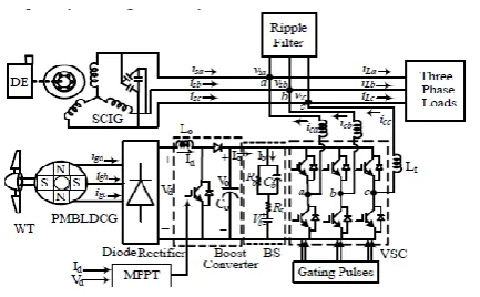
SYSTEM CONFIGURATION AND CONTROLFigure 1. Schematic diagram of Wind-Diesel micro grid
A. Back Propagation Feed Forward Network Controller
BPFF (Back Propagation Feed Forward) based control calculation manages voltage and recurrence of the micro grid [24-25]. In this plan, multi-layered encourage forward system is included an info layer, shrouded layer and a yield layer. The info flag goes in nourish forward bearing from an information layer towards a yield layer on layer by layer premise. Administered learning with back-spread calculation is executed here which chips away at blunder rectification learning principles to accomplish craved yields. Its portrayal is given here as indicated by Fig.2. In-stage and quadrature layouts of PCC voltage are computed as, The pinnacle terminal voltage Vt is characterized asIn-stage and quadrature formats of PCC voltage are ascertained as,
The pinnacle terminal voltage Vt is characterized as,
√ ( ) (1)
where vsa,vsb, vsc are phase voltages.
The in-phase unit templates are expressed as, , , (2)
The quadrature unit templates are defined as,
( )
√ (3)
√ (4)
√ (5)
Reference input streams are processed with synaptic weight estimations of load streams, a dynamic and responsive power segments. Three-layers as an info, covered up and a yield layers are taken to understand the control. Input layer neurons in its first half bit as a total capacity for dynamic and receptive power segment of load current for "b" stage are communicated as,
(6)
(7)
where w is the underlying estimation of snaptic weight. Both the segments of stage 'an and c' (ILpa, ILpc, ILqa and ILqc) are ascertained in the comparative way. These qualities are passed through second part as actuation capacity of info neurons , which are sigmoid capacities here. The yield of info layer neurons for stage "b" are communicated as
⁄ (8)
⁄ (9)
Additionally conditions for stage "an" and "c" (Xpa, Xpc, Xqa and Xqc) are likewise processed. These info layer yields are bolstered to the information hub of covered up layer and accumulation capacity of this layer for stage "b" are communicated as,
(10)
(11)
Different conditions for Ipal, Ipcl, Iqal and Iqcl are additionally ascertained in comparable way. Here w1, wpa, wpb, wpc are a few constants values between (0, 1) to introduce the weights. These qualities are refreshed by back engendering mistake remedy run the show. Remedied weights of stage "b" dynamic and responsive power segments of load streams wpb and wqb at rth examining time bare as,
are gone through enactment work i.e. sigmoid capacity here. The dynamic what's more, responsive power part of load streams wpal, wpcl,wqal and wqcl are computed like that of stage "b" as,
⁄ (12)
⁄ (13)
A bundancy of the normal dynamic and responsive power parts of load streams is characterized as,
(14)
(15)
DC part of the weighted segment is extricated through LPF as these are standardized values between (0, 1). In this manner to get genuine estimation of dynamic and responsive power segments of load streams they are scaled with an and b calculates individually. These qualities are given in Appendices. Dynamic power part of reference info current can be evaluated by subtracting wind dynamic segment, wpw devoured from dynamic segment of load present as Dynamic power part of reference information current can be evaluated by subtracting wind dynamic part, wpw devoured from dynamic part of load present as,
(16)
(17)
The responsive segment of reference info current is processed utilizing a PI controller. The AC transport voltage mistake Ve is communicated as,
(18)
Weighted estimation of PI controller to manage terminal voltage at rth moment is computed as,
Figure 2. Schematic diagram of BPFF control Technique
The key reference dynamic and responsive power segments of the 3-stage input streams are ascertained
, , (19)
, , (20)
, ,
(21)
These 3-stage reference input streams (i*sa, i*sb, i* sc) and detected information streams isa, isb, isc ) are contrasted with produce PWM beats for the exchanging of VS
B. Maximum Power Point Tracking (MPPT) Scheme The obligation cycle of DC-DC support converter is figured straightforwardly as per the MPPT. For MPPT, the subordinate of yield power and voltage of diode extension must be zero i.e. expansion of
immediate conductance and incremental
Conductance, Z= (Id/Vd+ΔId/ΔVd) is zero. Because of progress in any individual parameter, if the point moves towards right hand side and Z ends up plainly negative, the obligation cycle increments to keep up the MPPT. In the event that the point moves towards left hand side and Z ends up plainly positive then the obligation cycle reductions to keep up the MPPT.
III.
PROPOSED ENHANCE VSG CONTROL SCHEMEThe proposed improved VSG control plan is appeared in Figure 4. Contrasted with the essential VSG control, two noteworthy changes are made, i.e., the stator reactance adjuster and the bus voltage estimator, as appeared in Figs. 4(b) and 4(c), individually. The capacity of stator reactance adjuster is to change the output reactance of the DG freely. It is working as a virtual impedance controller. The virtual stator inductor is figured it out by increasing output current by the virtual stator inductor in stationary casing. It will be more exactness if inductor current through is utilized. Be that as it may, this builds the quantity of current sensors, which is redundant. As the current flowing into at fundamental frequency is not as much as few percent of the inductor current, utilizing output current rather than inductor current does not influence the execution of the control plot. Tuning of virtual stator inductor is recommended to set aggregate output
reactance for both DGs in same substantial per unit esteem. The objective esteem is proposed to be 0.7 pu since it is a run of the mill an incentive for the add up to direct-axis transient reactance of a genuine SG.
( )
(11)
The and are considered
as known parameters in this paper. As the size of microgrid is for the most part little, the line distance is effortlessly to be measured or encouraged by the organizer. Regardless of the possibility that it is not the situation, a few online estimation then again keen tuning strategies for Zline.
With the proposed outline of stator reactance altaretion, oscillation in a VSG-control-based microgrid ought to be practically dispensed with amid a loading transition in islanded mode. Especially, transition from grid- associated mode to islanded
mode can likewise be considered as a loading transition; along these lines, the oscillation during an islanding occasion ought to likewise be disposed of with the proposed control system, as it is demonstrated by simulation results next area.
The rule of bus voltage estimator in Figure 4(c) is comparable to that of stator reactance adjuster in Figure 4(b). By ascertaining the line voltage drop in stationary casing utilizing measured output current and line impedance information, the bus voltage can be assessed from the distinction of output voltage furthermore, computed line voltage drop. Since the as it is examined in last segment, precise reactive power sharing can be acquired by utilizing evaluated bus voltages as the input references of "Q Droop" rather than particular output voltages of DGs. In spite of the fact that the rule of exhibited bus voltage estimator is not new, utilizing this estimator to acknowledge correspondence less precise reactive power sharing can be considered as a commitment in the introduce work.
Be that as it may, if there is an estimation mistake in ̂ , it will bring about a reactive power sharing
error. Assuming ̂ ̂ and ̂
̂ ,
( ̂ ̂ ) (12)
An adaptive neuro-fuzzy inference system
estimator. For utilizing the ANFIS as a part of a more productive and ideal way, one can utilize the best parameters acquired by hereditary calculation. ANFIS: Artificial Neuro-Fuzzy Inference Systems
ANFIS are a class of adaptive networks that are functionally equivalent to fuzzy inference systems.
ANFIS represent Sugeno e Tsukamoto fuzzy models.
ANFIS uses a hybrid learning algorithm.
In the field of artificial intelligence neuro-fuzzy alludes to mixes of fake neural systems and fuzzy rationale. Neuro-fuzzy hybridization brings about a half and half astute network that synergizes these two procedures by joining the human-like thinking style of fuzzy networks with the learning and connectionist
structure of neural systems. Neuro-fuzzy
hybridization is genarelly named as Fuzzy Neural Network (FNN) or Neuro-Fuzzy System (NFS) in the writing. Neuro-fuzzy network (the more mainstream term is utilized from this time forward) fuses the human-like thinking style of fuzzy networks using fuzzy sets and a semantic model comprising of an arrangement of IF-THEN fuzzy standards. The primary quality of neuro-fuzzy networks is that they are widespread approximates with the capacity to request interpretable IF-THEN principles. The quality of neuro-fuzzy networks includes two conflicting necessities in fuzzy displaying: interpretability versus exactness. Practically speaking, one of the two properties wins. The neuro-fuzzy in fuzzy demonstrating research field is separated into two zones: semantic fuzzy displaying that is centered on interpretability, for the most part the Mamdani model; and exact fuzzy demonstrating that is centered around exactness, primarily the Takagi-Sugeno-Kang (TSK) model.
Representing fuzzification, fuzzy inference and defuzzification through multi-layers feed-forward connectionist networks. It must be pointed
out that interpretability of the Mamdani-type neuro-fuzzy systems can be lost. To improve the interpretability of neuro-fuzzy systems, certain measures must be taken, wherein important aspects of interpretability of neuro-fuzzy systems are also discussed.
A recent research line addresses the data stream mining case, where neuro-fuzzy systems are sequentially updated with new incoming samples on demand and on-the-fly. Thereby, system updates do not only include a recursive adaptation of model parameters, but also a dynamic evolution and pruning of model in order to handle concept drift and dynamically changing system behavior adequately and to keep the systems/models "up-to-date" anytime.
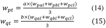
Function member ship of input1
Function member ship of input2
Figure 3. ANFIS structure
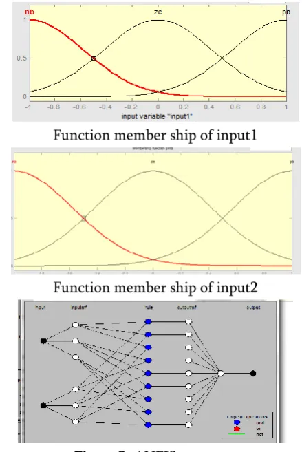
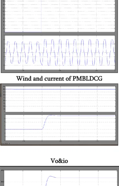
The wind speed differs from 9 m/s to 11 m/s, as needs be PMBLDC generator yield additionally increments as far as iPMBLDCG. This expansion in power likewise expands the yield current (Io) and yield control (Po) of the lift converter.
Wind and current of PMBLDCG
Vo&io
Po
Figure 4. MPPT’ performance under wind variation
The remunerating streams (ica, icb, icc) are changed by the prerequisite of receptive power pay to keep up the terminal voltage (Vt) close to the reference esteem.
Figure 5. Intermediate signals of micro grid under nonlinear load
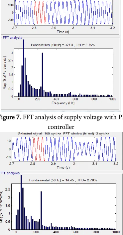
Figure 7. FFT analysis of supply voltage with PI controller
Figure 8. FFT analysis of supply current with PI
Figure 9. FFT analysis of load current with PI controller
V.
SIMULATION RESULTS USING ANFISCONTROLLER
Wind and current of PMBLDCG
Vo&io
Po
Figure 11. Intermediate signals of microgrid under nonlinear load
Figure 12. Dynamic performance of micro grid under nonlinear load
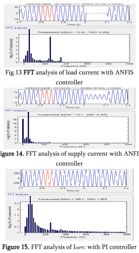
Fig.13 FFT analysis of load current with ANFIS controller
Figure 14. FFT analysis of supply current with ANFIS controller
Figure 15. FFT analysis of IsbPFC with PI controller
VI.
CONCLUSION
power utilizing a lift converter and nourishes to the battery and burdens. Amid low wind conditions, battery and DG deal with load request. A correlation of reproduced and test results is made to demonstrate the exactness of the BPFF control using ANFIS controller calculation.
VII.
REFERENCES
[1]. M. Hook, A. Sivertsson, and K. Aleklett,"alidity of the fossil fuel production outlooks in the IPCC Emission Scenarios" Natural Resources Research, vol. 19, no. 2, pp. 63-81, June 2010. [2]. F. Mushtaq, W. Maqbool, R. Mat, and F.N. Ani,
"Fossil fuel energy scenario in Malaysia- prospect of indigenous renewable biomass and coal resources," in proc. of IEEE Conference on Clean Energy and Technology (CEAT), 2013, 18-20 Nov. 2013, pp.232-237.
[3]. N. Bauer, I. Mouratiadou, G. Luderer, Lavinia Baumstark, R. J. Brecha, Ottmar Edenhofer, and Elmar Kriegler, "Global fossil energy markets and climate change mitigation – an analysis with REMIND" Springer, Oct, 2013.
[4]. Bin Wu, Y. Lang, N. Zargari, and S. Kouro, "Power Conversion and Control of Wind Energy Systems", John Wiley & Sons, Inc., Hoboken, New Jersey, 2011.
[5]. Gilburt M. Master, "Renewable and Efficient Electric Power Systems", John Wiley & Sons, Inc., Hoboken, New Jersey, 2004.
[6]. K.F. Krommydas, and A.T. Alexandridis, "Modular Control Design and Stability Analysis
of Isolated PV-Source/Battery-Storage
Distributed Genaretion Systems," IEEE Journal on Emerging and Selected Topics in Circuits and Systems, vol.5, no.3, pp.372-382, Sept. 2015. [7]. A. Elmitwally, and M. Rashed, "Flexible
Oparetion Strategy for an Isolated PV-Diesel Microgrid Without Energy Storage," IEEE Trans. on Energy Conversion, vol.26, no.1, pp.235-244, March 2011.
[8]. Miao Zhixin, A. Domijan, and Fan Lingling, "Investigation of Microgrids With Both Inverter
Interfaced and Direct AC-Connected
Distributed Energy Resources," IEEE Transactions on Power Delivery, vol.26, no.3, pp.1634-1642, July 2011.
[9]. M. Arriaga, C.A. Canizares, and M. Kazareni, "Renewable Energy Alternatives for Remote Communities in Northern Ontario, Canada," IEEE Trans. on Sustainable Energy, vol.4, no.3, pp.661-670, July 2013.
[10]. Dong-Jing Lee and Li Wang, "Small-Signal Stability Analysis of an Autonomous Hybrid Renewable Energy Power Genaretion/Energy
Storage System Part I: Time-Domain
Simulations," IEEE Trans. on Energy Conversion, vol.23, no.1, pp.311-320, March 2008.
KALEEM FOWZADH SHAIK currently he is pursuing her Master Degree in the department of Electrical & Electronic Engineering: Quba college of engineering & Technology, venkatachalam, SPSR Nellore dist., A.P, India
Mr. ATCHI RAMBABU
Received B.tech degree in 2011
from Jawaharlal Nehru
technological university,