NOTICE
The information contained in this document is believed to be accurate in all respects but is not warranted by Mitel Networks Corporation (MITEL®). The information is subject to change without notice and should not be construed in any way as a commitment by Mitel or any of its affiliates or subsidiaries. Mitel and its affiliates and subsidiaries assume no responsibility for any errors or omissions in this document. Revisions of this document or new editions of it may be issued to incorporate such changes.
No part of this document can be reproduced or
transmitted in any form or by any means - electronic or mechanical - for any purpose without written permission from Mitel Networks Corporation.
MITEL, SX-200, SUPERSET, SUPERCONSOLE 1000, MILINK, and LIGHTWARE are trademarks of Mitel Networks Corporation.
HYPERTERMINAL is a trademark of Hilgraeve Inc.
All other product names specified in this document are trademarks of their corresponding owners.
SX-200 Technician’s Handbook
50003703, Revision A LIGHTWARE 19 Release 3.2 Software
May 2003
® ™Trademark of MITEL Networks Corporation
Chapter 1 - Introduction
About This Handbook . . . 3
Purpose of This Handbook . . . 3
Who This Handbook is For . . . 3
Symbols Used in This Handbook . . . 3
Important Safety Instructions . . . 4
Where You Can Find More Information . . . 4
Configurations . . . 5 SX-200® EL System . . . 5 SX-200 ML (RM) System . . . 11 SX-200 ML (FD) PBX . . . 11 SX-200 LIGHT PBX . . . 13 SX-200 IP Node . . . 14
SX-200 SPINE Peripheral Bay . . . 16
SX-200 DIGITAL 672-Port PBX . . . 17
SX-200 DIGITAL 336-Port PBX . . . 18
SX-200 DIGITAL 456-Port PBX . . . 19
SX-200 DIGITAL 480-Port PBX . . . 20
LIGHTWARE™ 19 Software . . . 21
Chapter 2 - Routine Maintenance Is the System Healthy? . . . 25
Checking a System for Alarms . . . 26
Checking a System for Database Errors . . . 26
Backing Up a Customer Database . . . 27
SX-200 EL/ML . . . 27
SX-200 LIGHT/ DIGITAL . . . 28
Loading New Software Onto a System . . . 28
SX-200 LIGHT/ DIGITAL . . . 28
SX-200 EL/ML Remote Software Download . . . 29
SX-200 EL/ML Flash Memory Card Replacement . . . 33
Upgrading Set Firmware . . . 34
Boot Codes . . . 34
Firmware Revision Levels . . . 34
Firmware Commands . . . 34
System Log Messages . . . 35
Enabling Options or Changing Options . . . 36
Options Are Password Protected . . . 36
Enabling Options On a SX-200 EL/ML System . . . 36
Enabling Options On a SX-200 LIGHT/DIGITAL System . . . 36
Upgrading an SX-200 IP Node . . . 37
Upgrading from CD-ROM . . . 37
Trunk SMDR Records Field Summary . . . 42
Chapter 3 - Troubleshooting and Repair Identifying Faults . . . 49
Flowchart 1: Getting Started . . . 49
Flowchart 2: System Is Not Booting . . . 51
Flowchart 3: An Alarm Is Present . . . 52
Flowchart 4: Correcting Set / Dataset Problems . . . 53
Flowchart 5: Maintenance Terminal Problems . . . 55
Interpreting the Main Control Card Power-Up Error Codes . . . 56
Restoring the Database . . . 57
Restoring the SX-200 EL/ML Database . . . 57
Restoring the SX-200 LIGHT/DIGITAL Database . . . 57
Backing Up Log Entries . . . 58
Correcting System ID Errors . . . 59
If the System Reports a System ID Mismatch . . . 59
If the System Reports a Decryption Module Error . . . 59
Powering Down the Nodes . . . 60
Powering Down the SX-200 EL/ML Control Node . . . 60
Powering Down the SX-200 LIGHT Control Node . . . 60
Powering Down the Peripheral Nodes . . . 60
Powering Down the IP Node . . . 60
Powering Up the Nodes . . . 61
Powering Up the SX-200 EL/ML Control Node . . . 61
Powering Up the SX-200 LIGHT Control Node . . . 61
Powering Up the Peripheral Nodes . . . 61
Powering Up the IP Node . . . 61
Replacing Circuit Cards . . . 62
Replacing Peripheral Interface Cards . . . 62
Replacing a Main Controller Card . . . 63
Correcting Ground Path Problems . . . 64
Problems Caused by Incorrect PBX Grounding . . . 64
Ground Path AC Voltage Test . . . 64
Ground Path Resistance Test . . . 65
Testing the CO and PBX Ground Differential . . . 65
Checking the Port Connections to the PBX . . . 67
Checking the Receiver Allocation . . . 68
Checking the FIM/CIM Carrier Cards . . . 69
General Signaling & Supervision Concepts . . . 73
Loop Start Line/Trunk . . . 74
Ground Start Trunk . . . 76
Direct Inward Dial (DID)/Loop Trunk . . . 78
Ear & Mouth (E&M) Trunk . . . 80
T1 Trunk (D4 DS-1) . . . 84
PBX Property Management System Interface . . . 89
Property Management System Messages . . . 89
PBX and PMS Cannot Communicate . . . 92
Testing the PMS Interface of the PBX . . . 92
Disk Drive Maintenance . . . 94
SX-200 LIGHT/DIGITAL Floppy Disk Subsystem Troubleshooting Procedures . . . 94
Disk Drive Strapping . . . 96
Troubleshooting the SX-200 IP Node . . . 97
SX-200 IP Node Troubleshooting . . . 98
Test Line . . . 104
Chapter 4 - Programming Programming an Attendant Console . . . 110
Programming a Printer Port . . . 111
System Printer Port . . . 111
Dataset Printer Port . . . 111
Programming Stations/Sets Automatically . . . 112
Deleting a device and all dependent resources . . . 113
Deleting a range of devices and all dependent resources . . . 114
Programming a Single Line Voice Station . . . 115
Programming an Analog Device to a SIM2 . . . 116
Programming a Multi-Line Set . . . 117
Programming a Subattendant Set . . . 119
Programming a PRI card . . . 120
Programming a Non-Dial-In Trunk . . . 125
Programming a range of Non Dial-in Trunks . . . 126
Programming a Dial-In Trunk . . . 127
Programming a range of Dial-in Trunks . . . 128
Programming a DISA Trunk . . . 130
Programming ANI/DNIS on an Incoming Trunk . . . 131
Programming a CLASS Trunk . . . 134
Programming an SX-200 IP Node . . . 136
Initializing the SX-200 IP Node . . . 136
Registering IP Phones (Optional) . . . 140
Programming Symbol MiNET Wireless Phones (Optional) . . . 141
Install Symbol NetVision MiNET Phone Administrator Tool . . . 141
Programming a Circuit Descriptor for Hotel/Motel and ACD Datasets . . . 142
Programming the PMS Interface . . . 143
Programming Call Forwarding - External . . . 146
Feature Access Codes (CDE Form 02) . . . 148
Class of Service Options (CDE Form 03) . . . 151
System Options and Timers (CDE Form 04) . . . 159
CDE Cross Reference Guide . . . 164
SX-200 EL/ML Feature Limitations . . . 166
Chapter 5 - Installation Cabinet Card Assignments . . . 173
SX-200 EL Control Cabinet Card Assignments . . . 173
SX-200 EL Peripheral Cabinet Card Assignments . . . 174
SX-200 ML (RM) Cabinet Card Assignments SX-200 ML (FD) Cabinet Card Assignment . . . 177
SX-200 LIGHT Cabinet Card Assignment . . . 178
SX-200 SPINE Peripheral Bay Module Assignment . . . 179
SX-200 Digital 672-Port Cabinet Card Assignment . . . 180
SX-200 Digital 336-Port Control Cabinet Card Assignment . . . 181
SX-200 Digital 456-Port Cabinet Card Assignment . . . 182
SX-200 Digital 480-Port Cabinet Card Assignment . . . 183
SX-200 DIGITAL Cable Routing . . . 184
SX-200 EL/ML Configuration Rules . . . 185
Initial Power-up Procedure (SX-200 EL/ML) . . . 192
System Initialization Sequence . . . 194
SX-200 EL/ML Initialization . . . 194
SX-200 LIGHT/DIGITAL Initialization . . . 195
Adding a Peripheral Cabinet . . . 198
Peripheral Interface Cards and Modules . . . 199
Control and Digital Services Cards and Modules . . . 202
E&M Trunk Card Settings . . . 204
Adding an SX-200 IP Node . . . 207
SX-200 EL/ML Peripheral Interface Card Slot Assignments . . . 210
Adding a PKM . . . 238
PKM to an Attendant Console . . . 241
Chapter 6 - Maintenance Commands Basic Commands . . . 245
Entering Command Sequences . . . 245
Logging In . . . 245
Logging Out . . . 246
Displaying the Card Configuration . . . 246
Showing the System Identity . . . 246
Log Commands . . . 247
System Commands . . . 248
Report Commands . . . 252
Diagnostic Commands . . . 254
Traffic Measurement Commands . . . 258
How do I print a procedure from the infobase? . . . 265
How do I export a section of the infobase to a word processing file? . . . 265
How do I get more information? . . . 266
How do I search the entire infobase? . . . 266
How do I search a section of the infobase? . . . 266
Index
Figures
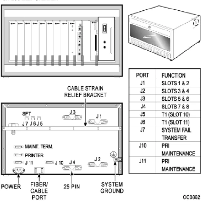
Figure 1: SX-200 ELx Cabinet ... 6
Figure 2: SX-200 ML (RM) and (FD) PBX ... 12
Figure 3: SX-200 LIGHT PBX ... 13
Figure 4: SX-200 IP Node Configuration ... 15
Figure 5: SX-200 SPINE Peripheral Bay ... 16
Figure 6: SX-200 DIGITAL (672-Port) PBX ... 17
Figure 7: SX-200 DIGITAL (336-Port) PBX ... 18
Figure 8: SX-200 DIGITAL (456-Port) PBX ... 19
Figure 9: SX-200 DIGITAL (480-Port) PBX ... 20
Figure 10: Removing the bottom panel ... 39
Figure 11: Removing the flash memory card ... 40
Figure 12: Inserting the flash memory card ... 41
Figure 13: Loop Start Line/Trunk ... 74
Figure 14: Ground Start Trunk ... 76
Figure 15: Direct Inward Dial (DID)/Loop Trunk ... 78
Figure 16: E&M Trunk - Type I (2-wire) ... 81
Figure 17: E&M Trunk - Type V (4-wire) ... 82
Figure 18: T1 Trunk Synchronization ... 84
Figure 19: SX-200 EL Control Cabinet Card Assignments ... 173
Figure 20: SX-200 EL Peripheral Cabinet Card Assignments ... 174
Figure 21: SX-200 ML (RM) Cabinets with BCC III Cards ... 175
Figure 22: SX-200 ML (RM) Cabinets with BCC II Cards ... 176
Figure 23: SX-200 ML (RM) Cabinet with a PRI Card ... 176
Figure 24: SX-200 ML (FD) Cabinet Card Assignment ... 177
Figure 25: SX-200 LIGHT Cabinet Card Assignment ... 178
Figure 26: SX-200 SPINE Peripheral Bay Module Assignment ... 179
Figure 27: SX-200 Digital 672-Port Cabinet Card Assignment ... 180
Figure 28: SX-200 Digital 336-Port Control Cabinet Card Assignment ... 181
Figure 29: SX-200 Digital 456-Port Cabinet Card Assignment ... 182
Figure 30: SX-200 Digital 480-Port Cabinet Card Assignment ... 183
Figure 31: S1 Switch Settings for the PRI Card ... 190
Figure 32: S1 Switch Showing 1 Closed ... 205
Figure 33: S1 Switch Settings on the PRI Card ... 205
Figure 34: Connecting a Triple CIM Card to the SX-200 IP Node ... 207
Figure 35: Connecting an SX-200 IP Node to an Ethernet Switch ... 208
Figure 36: PKM Connections to a SUPERSET™ 4025 ... 239
Figure 37: PKM Connections to a SUPERSET 4150 ... 239
Figure 38: 5448 PKM Connections to a 5220 IP Phone ... 240
Tables
Table 1: Firmware Commands ... 35
Table 2: Summary of Fields in Trunk SMDR Records ... 42
Table 3: Main Control Card Error Code Summary ... 56
Table 4: SX-200 SPINE Maximum Receiver Combinations Available ... 68
Table 5: Maximum Number of T1 Trunk Cards Prior to LIGHTWARE 18 ... 72
Table 6: Loop Start Line/Trunk Summary ... 74
Table 7: Ground Start Trunk Summary ... 76
Table 8: Direct Inward Dial/Loop Trunk Summary ... 79
Table 9: E&M Trunk Summary ... 82
Table 10: A-B Signalling States (Tie/E&M) ... 87
Table 11: A-B Bit Signalling Example (T1/CO) ... 88
Table 12: PMS Keyboard Commands ... 91
Table 13: Floppy Disk Troubleshooting Summary ... 94
Table 14: Floppy Disk Drive Error Code Summary ... 95
Table 15: SX-200 IP Node Troubleshooting Table ... 98
Table 16: Test Line Command Codes ... 105
Table 17: Test Line Status Indicator Codes ... 106
Table 18: Test Line Status Tones ... 107
Table 19: ANI/DNIS Digits on Phone Display (COS Option 502 Enabled and COS Option 613 Disabled) ... 132
Table 20: ANI/DNIS Digits on Phone Display (COS Option 502 Enabled and COS Option 613 Enabled) ... 133
Table 21: ANI/DNIS for ACD Agents ... 133
Table 22: Feature Access Codes ... 148
Table 23: Class of Service Options ... 151
Table 24: LIGHTWARE 19 Release 2.0 and greater System Options and Timers ... 159
Table 25: Feature Limitations ... 166
Table 26: SX-200 SPINE Configuration Rules ... 179
Table 27: Cable Assignments for SX-200 DIGITAL Cabinets ... 184
Table 28: Main Control Card Codes ... 194
Table 29: Main Control Card Test Status Codes ... 195
Table 30: Main Control Card Power-Up Error Code Summary ... 196
Table 31: Peripheral Interface Cards and Modules ... 199
Table 32: Digital Control and Digital Services Cards and Modules ... 202
Table 33: E&M Trunk Module Switch Settings ... 204
Table 34: Control Resource Card Switch Setting ... 206
Table 35: BRI Port to Tip/Ring Assignment ... 211
Table 36: SFT Port (J7) ... 212
Table 38: Copper Interface Ports ... 213
Table 39: Maintenance Module Port ... 214
Table 40: T1 or PRI Trunk Port (J5 and J6, BCC III and PRI Faceplates) ... 214
Table 41: T/R Cable Assembly Pinouts for SX-200 SPINE ... 215
Table 42: SX-200 EL or SX-200 ML (RM) Tip and Ring Assignments ... 216
Table 43: SX-200 EL or SX-200 ML (RM) Universal Card Tip and Ring Assignments ... 218
Table 44: SX-200 DIGITAL Peripheral Bay Tip and Ring Assignments (High-power Slots) ... 220
Table 45: SX-200 Digital Tip and Ring Assignments for Universal Card Modules ... 222
Table 46: SX-200 DIGITAL Tip and Ring Assignents (Low-power Slots) ... 224
Table 47: USOC Connector Pin Designations ... 226
Table 48: Analog Bay P1 and P7 Tip and Ring Assignments ... 228
Table 49: Analog Bay P2 and P8 Tip and Ring Assignments ... 230
Table 50: Analog Bay P3 and P9 Tip and Ring Assignments ... 232
Table 51: Analog Bay P4 and P10 Tip and Ring Assignments ... 234
Table 52: Interconnect Card P19 Tip and Ring Assignments ... 236
Table 53: Log Level Functions ... 247
Table 54: System Level Functions ... 248
Table 55: Report Level Functions ... 252
Table 56: Diagnostic Level Functions ... 254
Figure 3: SX-200 LIGHT PBX ...13
Figure 4: SX-200 IP Node Configuration ...15
Figure 5: SX-200 SPINE Peripheral Bay ...16
Figure 6: SX-200 DIGITAL (672-Port) PBX ...17
Figure 7: SX-200 DIGITAL (336-Port) PBX ...18
Figure 8: SX-200 DIGITAL (456-Port) PBX ...19
Figure 9: SX-200 DIGITAL (480-Port) PBX ...20
Figure 10: Removing the bottom panel ...39
Figure 11: Removing the flash memory card ...40
Figure 12: Inserting the flash memory card ...41
Figure 13: Loop Start Line/Trunk ...74
Figure 14: Ground Start Trunk ...76
Figure 15: Direct Inward Dial (DID)/Loop Trunk ...78
Figure 16: E&M Trunk - Type I (2-wire) ...81
Figure 17: E&M Trunk - Type V (4-wire) ...82
Figure 18: T1 Trunk Synchronization ...84
Figure 19: SX-200 EL Control Cabinet Card Assignments ...173
Figure 20: SX-200 EL Peripheral Cabinet Card Assignments ...174
Figure 21: SX-200 ML (RM) Cabinets with BCC III Cards ...175
Figure 22: SX-200 ML (RM) Cabinets with BCC II Cards ...176
Figure 23: SX-200 ML (RM) Cabinet with a PRI Card ...176
Figure 24: SX-200 ML (FD) Cabinet Card Assignment ...177
Figure 25: SX-200 LIGHT Cabinet Card Assignment ...178
Figure 26: SX-200 SPINE Peripheral Bay Module Assignment ...179
Figure 27: SX-200 Digital 672-Port Cabinet Card Assignment ...180
Figure 28: SX-200 Digital 336-Port Control Cabinet Card Assignment ...181
Figure 29: SX-200 Digital 456-Port Cabinet Card Assignment ...182
Figure 30: SX-200 Digital 480-Port Cabinet Card Assignment ...183
Figure 31: S1 Switch Settings for the PRI Card ...190
Figure 32: S1 Switch Showing 1 Closed ...205
Figure 33: S1 Switch Settings on the PRI Card ...205
Figure 34: Connecting a Triple CIM Card to the SX-200 IP Node ...207
Figure 35: Connecting an SX-200 IP Node to an Ethernet Switch ...208
Figure 36: PKM Connections to a SUPERSET 4025 ...239
Figure 37: PKM Connections to a SUPERSET 4150 ...239
Figure 38: 5448 PKM Connections to a 5220 IP Phone ...240
Table 3: Main Control Card Error Code Summary ... 56
Table 4: SX-200 SPINE Maximum Receiver Combinations Available 68 Table 5: Maximum Number of T1 Trunk Cards Prior to LIGHTWARE 18 72 Table 6: Loop Start Line/Trunk Summary ... 74
Table 7: Ground Start Trunk Summary ... 76
Table 8: Direct Inward Dial/Loop Trunk Summary ... 79
Table 9: E&M Trunk Summary ... 82
Table 10: A-B Signalling States (Tie/E&M) ... 87
Table 11: A-B Bit Signalling Example (T1/CO) ... 88
Table 12: PMS Keyboard Commands ... 91
Table 13: Floppy Disk Troubleshooting Summary ... 94
Table 14: Floppy Disk Drive Error Code Summary ... 95
Table 15: SX-200 IP Node Troubleshooting Table ... 98
Table 16: Test Line Command Codes ... 105
Table 17: Test Line Status Indicator Codes ... 106
Table 18: Test Line Status Tones ... 107
Table 19: ANI/DNIS Digits on Phone Display (COS Option 502 Enabled and COS Option 613 Disabled) 132 Table 20: ANI/DNIS Digits on Phone Display (COS Option 502 Enabled and COS Option 613 Enabled) 133 Table 21: ANI/DNIS for ACD Agents ...133
Table 22: Feature Access Codes ... 148
Table 23: Class of Service Options ... 151
Table 24: LIGHTWARE 19 Release 2.0 and greater System Options and Timers 159 Table 25: Feature Limitations ... 166
Table 26: SX-200 SPINE Configuration Rules ... 179
Table 27: Cable Assignments for SX-200 DIGITAL Cabinets ... 184
Table 28: Main Control Card Codes ... 194
Table 29: Main Control Card Test Status Codes ... 195
Table 30: Main Control Card Power-Up Error Code Summary ... 196
Table 31: Peripheral Interface Cards and Modules ... 199
Table 32: Digital Control and Digital Services Cards and Modules ... 202 Table 33: E&M Trunk Module Switch Settings ... 204
Table 37: Music-on-Hold/Pager Unit Pinouts ...212
Table 38: Copper Interface Ports ...213
Table 39: Maintenance Module Port ...214
Table 40: T1 or PRI Trunk Port (J5 and J6, BCC III and PRI Face-plates) 214 Table 41: T/R Cable Assembly Pinouts for SX-200 SPINE ...215
Table 42: SX-200 EL or SX-200 ML (RM) Tip and Ring Assignments 216 Table 43: SX-200 EL or SX-200 ML (RM) Universal Card Tip and Ring Assignments 218 Table 44: SX-200 DIGITAL Peripheral Bay Tip and Ring Assignments (High-power Slots) 220 Table 45: SX-200 Digital Tip and Ring Assignments for Universal Card Modules 222 Table 46: SX-200 DIGITAL Tip and Ring Assignents (Low-power Slots) 224 Table 47: USOC Connector Pin Designations ...226
Table 48: Analog Bay P1 and P7 Tip and Ring Assignments ...228
Table 49: Analog Bay P2 and P8 Tip and Ring Assignments ...230
Table 50: Analog Bay P3 and P9 Tip and Ring Assignments ...232
Table 51: Analog Bay P4 and P10 Tip and Ring Assignments ...234
Table 52: Interconnect Card P19 Tip and Ring Assignments ...236
Table 53: Log Level Functions ...247
Table 54: System Level Functions ...248
Table 55: Report Level Functions ...252
Table 56: Diagnostic Level Functions ...254
About This Handbook
Purpose of This Handbook
This handbook provides
Quick reference to maintenance commands
Abbreviated instructions for frequently used procedures Programming aids
Troubleshooting flowcharts Installation information.
Who This Handbook is For
This handbook is for a certified technician.
Symbols Used in This Handbook
Indicates a hazardous situation which, if you don’t avoid, could result in injury or death
Indicates a situation which, if you don’t avoid, could result in damage to the equipment
Identifies an important note or a useful tip Identifies an important cross reference
Important Safety Instructions
WARNING: Failure to follow all instructions may result in improper equipment operation and/or risk of electrical shock.
See MITEL® document PN 56004737, Safety Instructions, for general safety information. The Safety Instructions document is packaged with each system.
Where You Can Find More Information
See the MITEL SX-200® EL/ML Technical Documentation for more
Configurations
SX-200 EL System
The SX-200 EL system contains one control cabinet with the following components:
A Main Control Card IIIEL (MCC IIIEL) or Main Control Card IIIELx (MCC IIIELx) in slot 12
One Bay Control Card (BCC II or BCC III) in slot 9 One Bay Power Supply
Up to two Control Dual FIM Carriers (CFCII), Control Triple FIM Carriers (CFCIII), or Control Triple CIM (CTC) cards in slots 10 and 11
Up to 1 PRI card in unused slots 10 or 11
Up to two T1 Trunk cards in unused slots 10 or 11 Up to eight Peripheral Interface Cards in slots 1 to 8.
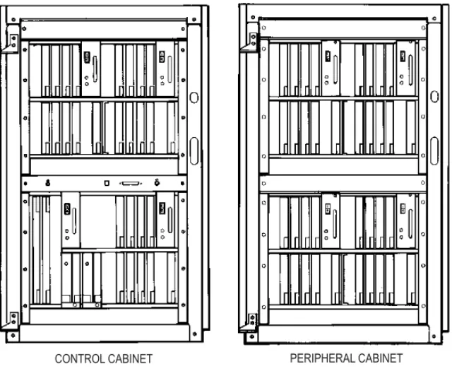
The SX-200 EL Control cabinet with an MCC IIIEL card or MCC IIIELx card supports up to six peripheral bays. The MCC IIIELx card can also support up to two SX-200 IP Nodes. The peripheral bays can be SX-200 EL peripheral cabinets, SX-200 LIGHT peripheral cabinets, SPINE Bays, ISDN Network Gateways, or PRI cards.
A seven cabinet system will provide a non-blocking system if a
MCC IIIELx card in the SX-200 ELx cabinet (PN 9109-600-002-NA) is installed with each of the following combinations:
Two CFCIII cards with LIGHTWARE 17 Release 3.1 or greater Two CTC cards set to the triple interface setting with LIGHTWARE 18
Release 2.0 or greater.
The SX-200 IP Node requires LIGHTWARE 19, Release 3.0 with Feature Level 4 enabled.
A seven cabinet system with a MCC IIIEL card and two CFCIII cards provides a system for low traffic configurations such as a hotel/motel environment.
The SX-200 EL and the SX-200 ML systems use the SX-200 ELx cabinet for the main control cabinet and the peripheral cabinets. Located on the rear of the cabinet are connectors for T1 trunks (J5 and J6), connectors for PRI maintenance (J10 and J11), a printer port, a maintenance terminal, and the SFT (System Fail Transfer) control port.
Connectivity from the Main Control Cabinet
The following cards with an interface module connect the main control cabinet to the peripheral bays. The Control FIM Carrier cards support fiber connectivity.The Control Triple CIM card and the PRI card support copper and fiber connectivity.
Control Dual FIM Carrier card - allows the fiber connection of up to two peripheral bays
Control Triple FIM Carrier card - allows the fiber connection of up to three peripheral bays
Control Triple CIM card - allows the copper connection of up to three peripheral bays; a copper connection may be substituted with a fiber connection
PRI card - allows the fiber or copper connection of one peripheral bay You can have either two or three links to each peripheral bay:
With a MCC IIIEL / ELx control card, the Control Dual FIM Carrier card provides three links per peripheral bay
With a MCC IIIEL control card, the Control Triple FIM Carrier card or the Control Triple CIM card (set to dual interface) provides two links per peripheral bay
With a MCC IIIELx control card (installed in a SX-200 ELx cabinet PN 9109-600-002-NA), the Control Triple FIM Carrier card and the Control Triple CIM card (set to triple interface) provide three links per peripheral bay
If you provide two links to each bay:
Calls must be evenly distributed across all bays Maximum channel blocking ratio is 0.58.
If you provide three links to each bay Maximum channel blocking ratio is 0.94.
Connectivity from the Peripheral Bays
Peripheral bays connect to the main control cabinet with the use of an interface module on the Peripheral FIM Carrier II card, Peripheral Interface Module Carrier card (PIMCC), BCC III, or PRI card. The Peripheral FIM Carrier II card supports a FIM. The PIMCC, BCC III, or PRI card support a FIM II or a CIM. A FIM II or CIM sits on a PIMCC when the peripheral cabinet does not have a BCC III.
.
As a guideline to achieve a P.0001 grade of service (one failure in 10,000 calls) for a bay connected via a Control Triple FIM Carrier, the recommended maximum
calls/hour is 500 based on traffic tables. With a typical call hold time of 2 minutes and 12 seconds the total Erlang rate is 18.33 (660 CCS) for the whole bay. The half bay would therefore be 9.17 Erlangs (330 CCS) at 250 calls/hour. It is important that calls be evenly distributed across all bays.
Remember to use the same distance variant of FIM or FIM II at both ends of the cable. You can connect a FIM to a FIM II.
Remember that the system sees the PRI card as a separate bay and therefore a PRI card in a peripheral cabinet must always have its own interface module (FIM II or CIM). Remember that the CIM suits co-located systems; not remote systems. The CIM comes in only one variant. The CIM supports a distance of up to 30 meters or 100 feet between cabinets.
Cabinet Configuration
The SX-200 EL system can have a maximum of seven bays.
The BCC III and the BRI card require LIGHTWARE 18 Release 2.0 or greater. The BCC III, BRI card, PRI card, and Control Triple CIM card require the SX-200 ELx cabinet.
In a main control cabinet: a FIM II or a CIM never goes on a BCC III, a FIM II or a CIM can go on a PRI card.
For CLASS line functionality on the ONS/CLASS Line card, you must install a DSP module (single) on the BCC III in the same SX-200 ELx cabinet. The ONS Line functionality on the ONS/CLASS Line card is backwards compatible with the older systems. The CLASS line functionality is dependant on LIGHTWARE 18 Release 2.0 or greater. For CLASS on the trunk side, you can install a LS/CLASS Trunk card in the SX-200 ELx cabinet or SX-200 ML (FD) cabinet, slots 1-8. The LS/CLASS Trunk card requires LIGHTWARE 19 Release 2.0. Prior to LIGHTWARE 19 Release 2, the system required a LS/CLASS module with the SPINE, a T1 (ANI/DNIS), or ISDN BRI, PRI, or Network Gateway (CLID and CNID).
A DSP module (single) on the BCC III provides CLASS generators for 1-8 ONS/CLASS Line cards in the same bay. System wide, this DSP module provides 16 conference bridges for Record a Call and 16 DTMF receivers.
MOSS System Option 96, Number of Links (0-8) monitors the number of T1 links from T1/E1 modules that the system will support. This count includes T1 links from the T1/E1 modules on the PRI cards and BCC III cards. This count does not include T1 links from the T1 cards. LIGHTWARE 18 Release 2.0 or greater supports a maximum of 8 T1
links (includes T1 links from T1/E1 modules and T1 cards) in the SX-200 EL system. Any bay can support up to two T1 links to a total of eight in the system.
LIGHTWARE 17 supports one digital bay with two T1 trunk cards and the other digital bays with one T1 trunk card to total a max of 7.
Remember to program CDE Form 04, Options 71 and 72, to match the configuration.
If a T1 trunk card is installed in slot 10 of a bay, you cannot install a peripheral interface cards in slot 5; if a T1 trunk card is installed in slot 11, you cannot install a peripheral interface card in slot 6. T1 cards in slots 10 and 11 are seen by the software as slots 5 and 6.
The two T1 links from the T1/E1 module on a BCC III card also occupy slots (in software) 5 and 6. The BCC III only supports one T1/E1 module.
The BRI card is a low power peripheral interface card (slots 1-8) and requires a BCC III in the same SX-200 ELx cabinet. If the BRI card is in a control cabinet, the BCCIII must have a Maintenance module. A cabinet holds a maximum of two BRI cards.
You can have one PRI card in a main control cabinet; up to two in a peripheral cabinet. PRI cards are installed in slots 10 or 11 in the SX-200 ELx cabinet Rev 4.4 or greater (PN 9109-600-002-NA ). The PRI card requires a Statum 3 MCC. The system counts the PRI card as a peripheral bay.
If a PRI card is installed in slot 10, you can install a peripheral interface card in slot 5; if a PRI card is installed in slot 11, you can install a peripheral interface card in slot 6. Because the system recognizes the PRI card as a peripheral bay, the PRI card does not occupy slots (in software) 5 or 6 in the bay that the card sits in. LIGHTWARE 18 and greater allows a maximum of 4 high power
cards in any of the slots 1 through 8 (there are no high/low power slots).High power cards are DID, Universal, COV and T1.
Low power cards are DNIC, OPS, ONS, BRI, LS/CLASS, and LS/GS.Unlike the T1 card, the PRI card is a separate bay and is not included in the count for the 4 high power cards.
If the cabinet has a BCC II, do not install more than seven DNICs per bay in high traffic applications. If you have more than seven DNICs per bay keep the device count to 84 or less. With two T1 cards in a bay, do not add more than five DNICs or 60 devices. With one T1 card in a bay, do not add more than six DNICs or 72 devices.If the cabinet has a BCC III, you can install eight DNICs per bay.
SX-200 ML (RM) System
The SX-200 ML (RM) system contains one control cabinet with the following components:
A Main Control Card IIIML (MCC IIIML) in slot 12 One Bay Control Card (BCC II or BCC III) in slot 9 One Bay Power Supply
One Control Dual FIM Carrier card, one Control Triple CIM card, or one PRI card in slot 10
Up to two T1 Trunk cards in unused slots 10 or 11 Up to eight Peripheral Interface Cards in slots 1 to 8.
The SX-200 ML system supports one peripheral bay. The one peripheral bay can be a SX-200 peripheral cabinet, SX-200 LIGHT peripheral cabinet, SPINE bay, or ISDN bay. The ISDN bay may be an ISDN Network Gateway or a PRI card.The PRI card fits into a main control cabinet.
SX-200 ML (FD) PBX
The SX-200 ML (FD) PBX cabinet resembles the SX-200 LIGHT cabinet. The SX-200 ML (FD) cabinet supports only one peripheral bay, SPINE Bay, or ISDN Network Gateway.
The SX-200 ML (FD) PBX contains one control cabinet with the following components:
a Main Control Card II (MCC II)
one Bay Control Card and one Bay Power Supply one Control FIM Carrier in slot 4 connecting to Bay 2 up to eight Peripheral Interface Cards in slots 1 to 8.
If the cabinet has a BCC II, do not install more than seven DNICs per bay in high traffic applications. If you have more than seven DNICs per bay keep the device count to 84 or less. With two T1 cards in a bay, do not add more than five DNICs or 60 devices. With one T1 card in a bay, do not add more than six DNICs or 72 devices.
. t
When a SX-200 ML (FD) PBX has a second bay, the Control FIM Carrier is installed in slot 4 of the control cabinet and therefore reduces the number of ports to 84 in the control cabinet.
SX-200 LIGHT PBX
The SX-200 LIGHT PBX consists of a Control cabinet with an MCC, a Control Resource card, two disk drives, and up to seven FIM carriers. Each 96-port digital peripheral bay (1 - 7) includes a Bay Control card (with attached FIM Carrier and FIM) and is connected to the Control cabinet by fiber cable.
SX-200 IP Node
You can connect up to two SX-200 IP Nodes to the SX-200 EL. The system requires one Control Triple CIM card (three onboard CIM circuits) in a 200 ELx Control Cabinet with a Main Control Card IIIELx.
The following connections are required to configure the SX-200 IP Node: Connections between peripheral bays and the main control cabinet
are made with standard CIM connections.
An Ethernet crossover cable connects the Control Triple CIM Card in the main control cabinet to CIM port on the IP Node. All voice and signalling communications are carried over this connection. Another Ethernet crossover cable connects the IP Node to the
Ethernet switch on the LAN.
The configuration rules that apply to connecting standard peripheral bays to the control cabinet through CIMs also apply to connecting IP Nodes. For more information about configuration, see the Configuration Rules in the SX-200 Technical Documentation for the
SX-200 ELx Control Cabinet
Bays supported by the SX-200 ELx System
Control Triple CIM Card and the SX-200 ELx System SX-200 IP Node Local Area Network Design Guidelines
Note: The Symbol MiNET Wireless Phones depicted in Figure 4 require
SX-200 SPINE Peripheral Bay
The SX-200 SPINE Peripheral Bay can be used with the SX-200 EL, SX-200 ML, and SX-200 LIGHT Control cabinets.
Refer to SX-200 SPINE Peripheral Bay Module Assignment
(page 179).
SX-200 DIGITAL 672-Port PBX
The SX-200 DIGITAL 672-port PBX consists of a Control cabinet with control bay 0, and digital peripheral bays 1, 2, and 3 (96 ports each). Its peripheral cabinet contains digital bays 4, 5, 6, and 7 (96 ports each). Bay 0 includes an MCC, a Switch Matrix Card, and two floppy disk drives.
SX-200 DIGITAL 336-Port PBX
The SX-200 DIGITAL 336-port PBX consists of a Control cabinet with COMBO bays 1 and 2 (144 ports), and digital peripheral bays 3 and 4 (96 ports each). The COMBO bay includes an MCC and two floppy disk drives. There is no peripheral cabinet.
SX-200 DIGITAL 456-Port PBX
The SX-200 DIGITAL 456-port PBX consists of a Control cabinet with COMBO bays 1 and 2 (144 ports), and digital bay 3 (96 ports). The COMBO bay includes an MCC and two floppy disk drives. The peripheral cabinet contains analog bay 4 (120 ports) and analog bay 5 (96 ports).
SX-200 DIGITAL 480-Port PBX
The SX-200 DIGITAL 480-port PBX consists of a Control cabinet with COMBO bays 1 and 2 (144 ports) and an analog bay 3 (120 ports). The COMBO bay includes an MCC and two disk drives. The peripheral cabinet contains analog bay 4 (120 ports) and analog bay 5 (96 ports).
LIGHTWARE 19 Software
The following types of SX-200 systems support the LIGHTWARE 19 software
SX-200 EL SX-200 ML (RM) SX-200 ML (FD).
LIGHTWARE 18 introduced the MOSS System Option #102, Feature Level to obtain the new features that are offered with major releases. The feature level for LIGHTWARE 19 Release 2.0 is 3.
LIGHTWARE 17 and greater software are not
available for the SX-200 LIGHT or the SX-200 DIGITAL systems.
Is the System Healthy?
System checklist
;
No alarms present;
No database errors;
Backed-up database available for SX-200 EL/ML onto PCChecking a System for Alarms
1. Log onto the maintenance terminal and select Maintenance mode.
The Maintenance screen displays the version of system software and the system alarm status.
2. Select the following commands:
REPORTS
SHOW ALARMS (DEVICE_TYPE or ALL)
or
REPORTS
SHOW STATUS (Bay/Slot/Circuit or SWID or Ext_Num or ALL)
SHOW ALARMS displays alarms by device type (or all)
SHOW STATUS displays status by Bay/Slot/Circuit (PLID) or SWID or Ext_Num or ALL or Logs Read All
Checking a System for Database Errors
1. Access CDE. 2. Select Form 01. 3. Select VERIFY DATA.
Refer to Logging In (page 245) for instructions on how to log into a maintenance terminal.
Backing Up a Customer Database
Keeping three backups allows you to go further back in time to find an error-free database.
SX-200 EL/ML
Backing up the database copies the database from memory to a file on the attached maintenance PC. Back up a database after you make changes to it. To back up the customer database, use
the Maintenance screen in the Terminal or Hyperterminal Communication’s Package and proceed with the following steps: 1. Select the following commands:
SYSTEM DATABASE BACKUP ENTER
The system prompts you for the file name.
2. Enter the file name. ENTER
CONFIRM
The system then prompts you to exit to a local Kermit session. Ensure that the Kermit session is set to binary mode because the customer database information must be saved as a binary file. 3. In the Kermit session, issue the RECEIVE command.
While the backup is in progress, the top seven-segment LED on the MCC shows “A”, and the lower seven-segment LED shows a dash that is circling in a clockwise direction.
After the file transfer has completed, the maintenance screen returns. The message "Download/Upload Successful " appears on the screen.
Think of a meaningful filename. It can include abbreviations for the name of a remote site, the purpose or function of the database, or the version of the software.
SX-200 LIGHT/ DIGITAL
To back up the customer database, from the Maintenance screen, do the following:
1. Select the following commands: SYSTEM
COPY DATABASE
The system verifies the data.
The system prompts the user to insert new disks into drives A and B. 2. Insert the new disks into drives A and B.
After inserting new disks, wait for 5 seconds before entering CONTINUE to allow the system to recognize the new disks. 3. Select CONTINUE.
The system notifies the user upon completion. 4. For the same level of software, select CONTINUE. 5. For a different level of software, select RESET.
Loading New Software Onto a System
SX-200 LIGHT/ DIGITAL
To load new software you must
1. Copy the existing database to new software disks. 2. Reset the system using the main control card switch.
SX-200 EL/ML Remote Software Download
Requirements: A 4 MB Flash card. Make sure the toggle switch on the edge opposite the connector edge of the Flash card has the Write Protect disabled. System option 109 (Remote Software Download) must be enabled.
This is a purchasable system option.
The latest software downloaded onto your PC provided by MITEL On-Line or MITEL Product Support.
Upgrading the System
Downloading LIGHTWARE 19 software for the BCC III and the MCC with a 4 Meg Flash card requires a two step procedure. You download the software from the MCC first and then download the software for the BCC III. It is recommended that you back up your database before you perform a system upgrade.
Downloading LIGHTWARE 19 software for the BCC III and the MCC with a 4 Meg Flash card requires a two step procedure. You download the software from the MCC first and then download the software for the BCC
The remote software download time can take up to 3 hours. We recommend that you do this operation during a slow time since the traffic on the switch affects the download time. To shorten the remote software
download time to approximately 90 minutes, increase the size of the packet length to 900 and change the block check type to 3 bytes CRC.
WARNING: After the files are loaded onto the flash, reboot the system to complete the upgrade. Once the system comes back up, the installed BCC III cards require an additional 20 minutes before returning to service. During this time, the BCC III cards must not be interrupted. If they are reset or powered down during this 20 minute timeframe, their self upgrade will fail and the cards will need to be repaired. A flashing green or red LED on a BCC III means the card is performing the self upgrade.
III. It is recommended that you back up your database before you perform a system upgrade.
1. Back up the database.
2. Launch the Hyperterminal application and set up a connection at 19.2 bps.
3. Logon to the maintenance terminal and load the new operating software from the PC.
Select the following commands from SYSTEM maintenance: DATABASE
SW_RESTORE CONFIRM.
4. When the message “Return to your local KERMIT session now” appears, return to your KERMIT session.
5. Use KERMIT to transfer and send the remote.fix file.
If the system only has a BCC II and the remote.fix file has completed, the maintenance screen shows the message “Download/Upload Successful”.
If the system has a BCC III, continue with the next steps.
6. If necessary, use KERMIT to transfer and send the bccIII.fix file. To see the status of the flash card, select the following commands: SYSTEM
SHOW IDENTITY.
7. After all the file transfers are complete and at a time of low or no traffic, return to the Maintenance application. Select SYSTEM,
Note that upgrading software for the BCC III with a 4 Meg Flash card always requires you to download the software for the main control card first.
8. Log into Maintenance to verify that the new load was correctly downloaded.
Note: For information on reimaging the flash card and rom_maingc.bin
files in approximately 2 minutes, access the Smart Tools Flash Card Software TSB available at MITEL On-Line.
To Speed Up the Remote Software Download
To speed up the remote software download, increase the packet length to 900 and the block check type to 3 bytes CRC, using the Kermit protocol on your maintenance terminal.
To change the packet length
1. Select SYSTEM from the Maintenance screen. 2. Select the following softkeys:
DATABASE SET_PARAM RECEIVE PACKET_SIZE ENTER
The following message will display: "Enter Packet Length (10-1024)"
3. Enter the packet length (900) and select CONFIRM.
The screen confirms your setting with a display of the Kermit Receive Parameters and the Kermit Send Parameters.
For non-Hyperterminal users, change the terminal application to match these packet length parameters.
To change the block check type
1. Select SYSTEM from the Maintenance screen: 2. Select the following softkeys:
DATABASE SET_PARAM BLOCK_CHECK ENTER
3. Enter the Block Check (03) and select CONFIRM.
The screen confirms your setting with a display of the Kermit Receive Parameters and the Kermit Send Parameters.
For non-Hyperterminal users, change the terminal application to match these block check parameters.
SX-200 EL/ML Flash Memory Card Replacement
1. Back up the database.
2. Power down the Control cabinet.
3. Remove the flash memory card and install the new flash
memory card. Make sure the toggle switch on the edge opposite the connector edge of the Flash card has the Write Protect disabled. After installing the card, look at the facing edge. You should see the switch in the down position.
4. Power up the system.
5. Enable new options if new feature options have been purchased. Refer to Backing Up a Customer Database (page 27).
Refer to Powering Down the Nodes (page 60).
Refer to Powering Up the Nodes (page 61).
Upgrading Set Firmware
Upgrade the firmware for SUPERSET™ 4025, SUPERSET 4090, SUPERSET 4125, and SUPERSET 4150 telephones, only if the revision on the system is higher than the set revision. The boot code and the firmware revision levels must be checked.
Boot Codes
The SUPERSET boot code must be at revision Boot 3.10 or greater or the SX-200 system cannot successfully upgrade the set’s firmware. The boot code appears when a set is first plugged in.
Firmware Revision Levels
The firmware revision level of the set that you are upgrading must meet the firmware revision level stated in SYSTEM maintenance. Use the
SET_FIRMWARE STATUS maintenance command to identify the
revision level.
Firmware Commands
Access the firmware commands in the SYSTEM maintenance level and then choose SET_FIRMWARE to obtain the softkeys to qualify your target set. See Table 1 on page 35.
If you attempt to upgrade a set with a boot code lower than 3.10, the system will erase the set’s firmware and you will not be able to download the new firmware. The set then becomes
System Log Messages
If a firmware download fails, the reason for the failure will be reported in the system logs. If a failure occurs, the download will be aborted and the remaining sets on the list will not receive the download.
Table 1: Firmware Commands Set_Firmware
Qualifiers Result
STATUS
Displays the software revision level the set is running and whether the set is scheduled for a download.
DOWNLOAD
Erases and updates the firmware on all specified sets. The set must be idle and the set’s firmware revision must be older than the firmware to be downloaded. ABORT_DOWNLOAD Removes specified sets from the
sched-uled download.
FORCE_DOWNLOAD
Forces the download to occur even if the set firmware is newer than the firmware being downloaded. This command allows a set’s firmware to be returned to a previous firmware version when required.
The conditions and restrictions that apply to the firmware download are described in Upgrading Set Firmware in the Maintain section of the SX-200 EL/ML Technical Documentation.
Enabling Options or Changing Options
Options Are Password Protected
Call the MITEL Order Desk to purchase a new set of options. You will receive a new MITEL options password that will enable the options on the system. The working hours for the MITEL Order Desk are Monday to Friday 8:00 to 18:00 E.S.T.
Enabling Options On a SX-200 EL/ML System
1. Select Customer Data Entry mode. 2. Select Form 04, System Options.
3. Set all purchasable options to match those on the MITEL Options Selection Sheet (MOSS). Set all other options as required. Press ENTER only once after each entry.
4. Enter the MITEL options password (from the MOSS sheet received with the software); press ENTER twice to activate the purchased options.
5. Quit the form.
An E.8 error appears on the MCC if the enabled options and purchased options do not match or if the password is incorrect. You can still program a system with an E.8 error but the bays will not bootup.
Enabling Options On a SX-200 LIGHT/DIGITAL
System
Verify that the correct decryption module is installed for the options required.
When no system identification is installed, or when invalid software is loaded into the system, the default system identification number 65535 appears.
Upgrading an SX-200 IP Node
Upgrading from CD-ROM
.
Installer's PC requirements
Windows NT 4.0 or Windows 2000 operating system FTP server running (with IIS installed)
A communications program such as VT100 or HyperTerm A serial connection to the SX-200 Maintenance port Windows 2000 users must clear the browser cache. You also need
The IP address of the SX-200 IP Node. The IP address must also be correctly programmed before you begin. For more information, see “Initializing the SX-200 IP Node” on page 137.
SX-200 IP Node software CD-ROM
Time: The entire upgrade procedure takes approximately 20 minutes. To upgrade the Sx-200 IP Node software
1. Connect both the PC and the SX-200 IP Node to the LAN.
2. Connect the serial cable from the PC to the Maintenance Port on the SX-200 IP Node.
3. From your PC, ping the SX-200 IP Node to verify that you have a TCP/IP connection.
4. Insert the Mitel Networks SX-200 IP Node software CD-ROM into the CD drive of the installer's PC.
5. Run the "Setup.exe" program from the CD. 6. Select New Installation.
The upgrade procedure will install new software in the IP Node.
7. Choose a location for the installSetup program to install files (normally this is C:\intpub\ftproot). The installSetup program provides a progress indicator and a log file.
8. Click Finish when prompted.
You are presented with a text file providing instructions.
9. Launch a data communication application, such as Hyperterminal on the PC.
10. Specify the PC COM port that is connected to the SX-200 IP Node Maintenance port.
11. Set the communication parameters: 9600, 8, N, 1, None. 12. Enter “reboot” to reboot the SX-200 IP Node.
13. Press a key at the "Press any key to stop auto-boot" prompt to stop the auto-boot.
14. At [VxWorks Boot] type “c” and then press Enter. 15. Change the following parameters as indicated:
- Boot device : motfcc - File name : Lite_Install
- Host inet : <the IP address of the ftp server PC host (your PC)> - User (u) : <user name for FTP server in PC host>
- Ftp password (pw) (blank = use rsh) : <password for FTP server in PC host>
- Flags (f) : 0x0 (this is the default setting and should not have to be changed).
16. Press the reset button on the SX-200 IP Node, or at the PC, enter "@" to reboot the SX-200 IP Node.
The software installation takes about 10 minutes. The SX-200 IP Node reboots two times.
Upgrading by Replacing Flash Memory
You can upgrade SX-200 IP Node software by replacing the flash memory card in the SX-200 IP Node.
To replace the flash memory card
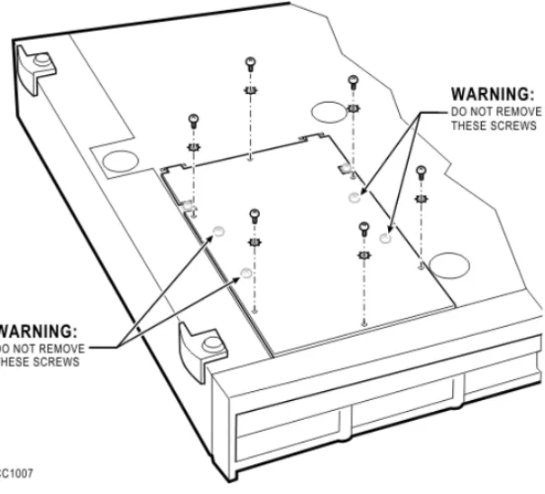
1. Disconnect all cables from the SX-200 IP Node. 2. Turn the SX-200 IP Node upside down.
3. Remove the six screws on the removable panel, as indicated in the figure below.
Do not remove the four screws indicated in the figure. If you remove the four screws, components will fall into the interior of the box.
4. Gently flip the panel open. Do not remove the panel. If you remove the panel, you might disconnect wires.
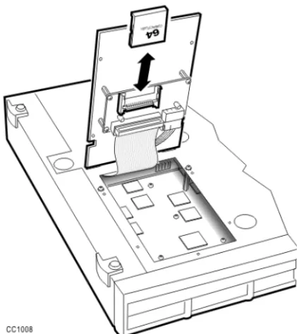
5. Pull out the flash memory card.
6. Insert the new flash memory card. Orient the card as shown in the following figure. The lip that extends from the bottom of the card must face the panel.
Figure 12: Inserting the flash memory card
7. Gently lower the panel. 8. Replace the six screws.
Trunk SMDR Records Field Summary
Table 2: Summary of Fields in Trunk SMDR RecordsNAME COLUMN FORMAT DEFINITION NOTE
Optional Long Call 1 z - = 5-9 min % = 10-29 min + = 30 or more min
Date 2-6 mm/dd mm = Month dd = Day mm = 01-12 dd = 01-31 Spacer 7 Start Time 8-13 hh:mmp hh = Hours mm = Minutes p = PM (12-hour clock) 00-2300-59 Spacer 14 Duration of call 15-22 hh:mm:ss hh:mm:ss = duration in hours:minutes:sec-onds hh = 00-18 mm = 00-59 ss = 00-59 maximum = 18:12:15 Spacer 23 Calling Party 24-27 pppp cccc = Extension Number, Tnnn = Trunk Number (CO), Xnnn = Trunk Number (Non-CO), mmmm = Attendant Console Directory Number c = 0-9, *, #nnn = 001-200 m = 0-9, *, # Spacer 28
Atten-dant 29 f * = Attendant -- = Attendant not involved Attendant answered or initiated the call, then transferred it to an extension. Leading Digits 30-33 cccc cccc = Access Code (outgoing and tandem calls only)
c = 0-9, *, #, left-justified Time to answer (Alter-nate) 30-32 ttt ttt = time in seconds *** = Call unanswered ttt = 000 - 255, leading zeroes output, incoming calls only Digits dialed on the trunk 34-59 xx .... x Up to 26 (20 if metering) digits dialed on the trunk
x = 0-9, *, or #; private speed call numbers are not recorded Optional Meter 55-59 mmmmm mmmmm = number of meter pulses mmmmm = 00000 to 65535, leading zeroes output Call Comple-tion Status 60 h A = Answer Supervi-sion B = Callee is Busy E = Caller Error T = TAFAS answered R = Incoming call recalled and was answered by transferer N = Incoming call recalled and was not answered by transferer Outgoing/Incoming Direct/Dial-In Incoming/Dial-In Incoming Incoming/Outgoing
Table 2: Summary of Fields in Trunk SMDR Records (continued)
NAME COLUMN FORMAT DEFINITION NOTE
Speed Call or Call Forward Flags 61 C,F, or R C = Number was Speed called (ARS implied)
F = Forwarded through External Call Forward
R = default (ARS implied)
Outgoing - All trunk calls are ARS by default. Called Party 62-65 qqqq cccc = Extension Number Tnnn = Trunk Number (CO) Xnnn = Trunk Number (Non-CO) mmmm = Attendant Console Directory Number c = 0-9, *, # nnn = 001-200 m = 0-9, *, # Transfer/ Confer-ence Call 66 K T = Supervised Transfer X = Unsupervised Transfer C = 3-Way or Conference Spacer 67 Third Party 68-71 rrrr cccc = Extension Number Tnnn = CO Trunk Number Xnnn = Non-CO Trunk Number mmm = Attendant c = 0-9, *, # n = 001 - 200 m = 0 - 9, *, # Spacer 72
Table 2: Summary of Fields in Trunk SMDR Records (continued)
Optional Account Code 73-84 aa .... a Length of 1 to 12 digits a = 0-9, space-filled Optional Spacer 85 Optional System Identifier 86-88 iii Programmed at System level i = 0-9 iii = 000-999 000 = no code entered Optional Spacer 89 Optional ANI CLASS Digits 90-99 nn .... n Up to 10 digits from an incoming ANI/DNIS or CLASS trunk n = 0-9, *, # Optional Spacer 100-102 Optional DNIS Digits 103-112 dd .... d Up to 10 digits from an incoming ANI/DNIS trunk d = 0-9, *, # Optional Spacer 113 Optional CLASS Name 114-128 15 char’s Up to 15 characters from an incoming CLASS trunk
Table 2: Summary of Fields in Trunk SMDR Records (continued)
NAME COLUMN FORMAT DEFINITION NOTE
Troubleshooting
and Repair
Identifying Faults
Flowchart 1: Getting Started
Yes
No
Flowchart 1:
Power subsystem is faulty.
Check Power Subsystem in the Control Cabinet.
Check connection between AC mains and rear of cabinet.
Check connection between PDU and backplane.
Replace Power Supply Swap Control Cabinet.
Are all system LEDs on the Control Cabinet
out? Start Yes No No Yes
Is the operating system intact? Check the Main Control Card’s “active” LED.
NO: any other state (e.g., on steady, off steady). YES: slow, steady flashing (1 second flash rate).
Maintenance terminal troubleshooting Flowchart 5: A B Is the maintenance terminal operating? (Ensure that maintenance
terminal is connected to the maintenance port on the Control Cabinet)
Flowchart 1: continued
Is a minor, major or critical alarm
LED on?
No Yes
Yes No
Wait until the system finishes booting. If a minor, major, or critical alarm is present, start this flowchart again.
Flowchart 2:
System is not booting.
An alarm is present.
Flowchart 3:
Correcting set / dataset problems.
Flowchart 4:
A B
Is the system in the process of a normal
Flowchart 2: System Is Not Booting
Is the Main Control Card in a cycle showing an Eb error code? Yes No No Is the Main Control Card in a cycle showing any
E-0/1/2/3/4/5/6/7/8/9 error codes? If E.8
see p.56.
Yes
Main Control Card (or onboard module) failure
Reseat all Control Cabinet cards Replace Main Control Card (and/or appropriate modules).
Replace Control Cabinet.
Flowchart 2:
System is not booting.
.
Boot Error
For SX-200 LIGHT, reseat all Control Cabinet cards.
Replace the system disks with known good copies (use known good backups because disk drive problems may corrupt the booting disks).
Check disk drive cables.
Replace disk drives (check that disks are in the correct drive).
For SX-200 EL/ML, power down, reseat the Flash card (PCMCIA) , reseat MCC, replace Flash Card, reseat System ID.
Any other combination of LEDs and 7-segment
LED displays not covered?
End
Main Control Card or Main Control Cabinet problem
Reseat all Control Cabinet cards.
Try swapping the suspect Main Control Card in a known working cabinet.
Try swapping a known working Main Control Card in the suspect cabinet.
Flowchart 3: An Alarm Is Present
Determine cause & location of the alarm by using REPORTS-SHOW-ALARMS-ALL.
=> Will show what category
(Lines/Trunks/Receivers/PCM Channels) has caused the alarm
LOGS-READ-ALL
=> Will show when and why the device(s) are not available to call processing
Determine current status of device by using REPORTS-SHOW-STATUS.
=> Will provide an immediate indication of status with respect to call processing (SWSTAT) and Maintenance (MTSTAT) Programs
An alarm is present.
Flowchart 3:
Return the device to service by using DIAGNOSTICS-RETURN TO SERVICE.
Replace the faulty card or device. (Ref E-docs - Install FRUs)
Test the device by using DIAGNOSTICS-TEST.
Flowchart 4: Correcting Set / Dataset Problems
Swap the set/dataset with a known working set/dataset (note the revision & model).
Return faulty set / dataset for repair.
To clear all dynamic user features for a set use DIAGNOSTIC-CLR-FEATURE Is the fault corrected? Yes No
Ensure that valid features, such as Do Not Disturb, are not causing the set to appear faulty.
Verify the firmware revision.
Try swapping the specific line card.
Hint: Remember to advise the users of the temporary loss of service. Is the problem related to feature functions or is the problem hardware based ?
=> Try swapping COS, COR, Tenant with a known working set to isolate programming area.
=> Determine what has recently been changed to cause this type of failure. => Determine COS, COR, Tenant commonality with other sets to rule out specific set hardware problems. =>Verify set errors.
D Flowchart 4:
Correcting set / dataset problems
Features
Flowchart 4: continued
D
See the troubleshooting procedure given for the set/dataset in Troubleshoot Sets of the SX-200 EL/ML Technical Documentation for other possible corrective actions.
Is the fault corrected ?
Check the cable and cable connections between the set and the line card.
=> Try connecting the device directly to the cross-connect field to verify against house wiring problems.
=> Try another port on the card to verify against backplane problems.
Yes
No
Return faulty card for repair.
Flowchart 5: Maintenance Terminal Problems
Refer to the Maintenance Terminal Troubleshooting Procedures in the SX-200 EL/ML Technical Documentation for further possible corrective actions.
Ensure that the terminal parameters are set correctly. They are:
VT100 / 8 Bits / No Parity / One Stop Bit ASCII character set
Xon/Xoff flow control 300-38, 400 baud Pin 4 & Pin 7 high
Try a selection of baud rates from 300-38,400 and press Esc-6 after each change.
Hint: If communication was lost during a session, the system considers the terminal logged-in and will only respond at the current logged-in speed. Try setting to the same speed and press Esc-6 (quit) (or Esc-5 from Maintenance application). If communication was never established, the system should respond at any speed.
Flowchart 5:
Maintenance Terminal troubleshooting
Try a screen reset by toggling the power off then on again.
Verify terminal and cabling to the maintenance port. If available, try connecting to a Peripheral Bay. Check the switch settings on the CRC. If a modem is connected, disconnect it.
Try Resetting the system - Hint: Remember to advise users of loss of service.
Interpreting the Main Control Card
Power-Up Error Codes
The error codes listed in Table 3 may appear on the Main Control Card numeric display during startup.
Note: 1. A normal running system may show other codes (card diagnostics or er-rors). However, during start-up, only the codes in this table are possible. Any other code shown during start-up indicates a faulty Main Control Card.
2. Codes possible AFTER start-up include card diagnostics codes (last card location tested - top number indicates bay number, bottom number indicates card slot number). Maintenance logs give results of test, pass or fail with cause.
Table 3: Main Control Card Error Code Summary Error
Code Likely Cause(s)
(blank) • Faulty power system. • Faulty Main Control Card. 0 • Faulty Main Control Card.
E. 8
• MOSS password was not purchased, a purchased option is not enabled, an enabled option is not purchased, the system password does not match, or the system id does not match. • Faulty System ID module.
C
• Faulty Flash memory or Main Control Card - This code shows for approximately 15 seconds during a proper power-up sequence. If the code remains, then a problem exists.
-• Nothing - indicates successful software download. This display may be immediately changed to display post-boot-up codes (see note 1).
Restoring the Database
Restoring the SX-200 EL/ML Database
To restore a customer database, your communication package must support the Kermit protocol. We recommend Terminal or Hyper Terminal.
1. Select the following maintenance commands: SYSTEM
DATABASE RESTORE ENTER
2. Exit to a local Kermit session.
3. Specify the name and location of the software file that you want to transfer to the system and send it to the system.
4. After the file transfer has completed, the message "Download/Upload Successful " appears on the screen.
After the database file is restored, the system automatically resets the system and the following entry is added to the log file : Main Control was reset due to Database Restore.
The system will reboot automatically when it detects the presence of a new database.
Restoring the SX-200 LIGHT/DIGITAL Database
1. Reset the system. 2. Remove the disks.
3. Insert the disks with the backed-up database. 4. Reset the system.
5. After the system restabilizes, copy the database to the previous disks.
Backing Up Log Entries
To back up log entries, your communication package must support the Kermit protocol.This log back-up procedure allows you to copy all maintenance log entries into a text file on either a directory on your PC’s hard disk, or on a diskette in the PC’s disk drive.
To back up log entries:
1. Select the following commands: SYSTEM
DATABASE LOGS_BACKUP ENTER
The system prompts you for the file name.
2. Enter the file name. 3. Press ENTER.
The system then prompts you to exit to a local Kermit session.
4. In the Kermit session, issue the Receive command.
While the backup is in progress, the top seven-segment LED on the MCC shows “A”, and the lower seven-segment LED shows a dash that is circling in a clockwise direction.
Ensure that the file name is meaningful to you. It can include abbreviations for the name of a remote site, the purpose or function of the database, the version of the software, or the number of the database.
Ensure that the Kermit session is set to text mode, because the maintenance log entries must copy into a text file.
Correcting System ID Errors
If the System Reports a System ID Mismatch
If the system reports a System ID mismatch, the problem may be one of the following:
The System ID module is faulty
The wrong System ID module is installed The Password is incorrect.
Verify that the options selected on Form 04, System Options, and the password entered match the data provided on the MOSS sheet. Contact MITEL Product Support for assistance. Have your tech ID number available.
If the System Reports a Decryption Module Error
If the system reports a decryption module error, your decryption module is faulty or wrong for the software that is in your system.
Powering Down the Nodes
Powering Down the SX-200 EL/ML Control Node
1. End any customer data entry sessions.
2. If you don’t have an up-to-date database backup, perform a database backup.
3. Switch-off power at the Bay Power Supply. Disconnect the power cords from the AC power source.
Powering Down the SX-200 LIGHT Control Node
1. End any customer data entry sessions.
2. If you don’t have an up-to-date database backup, perform a database backup.
3. Push the System Reset Button. 4. Remove the disks.
5. Turn off the AC power by pushing the 0 (off) button at the rear of the cabinet. Disconnect the power cords from the AC power source.
Powering Down the Peripheral Nodes
1. Set the Bay Power Supply switch to O (OFF). 2. Unplug the AC power cord from the rear of the node.
Powering Down the IP Node
Refer to Backing Up a Customer Database (page 27).
Powering Up the Nodes
Powering Up the SX-200 EL/ML Control Node
1. Connect the external AC power cord(s) at the rear of the node. 2. Switch on the Bay Power Supply switch to ON. Set the power
switch(es) on the rear of the node to I (ON) or set the Bay Power Supply switch to I (ON).
Powering Up the SX-200 LIGHT Control Node
1. Connect the external AC power cord(s) at the rear of the cabinet. 2. Set the power switch(es) on the rear of the node to I (ON). 3. Insert the disks into the MCC.
Powering Up the Peripheral Nodes
1. Connect the external AC power cord at the rear of the node. 2. Set the Bay Power Supply switch to I (ON).
Powering Up the IP Node
1. Ensure the SX-200 IP Node is NOT connected to a power source. 2. Using a serial cable, connect a PC to the Maintenance Port on the
IP Node.
3. Launch a data communication application, such as Hyperterminal on the PC.
4. Set the parameters: 9600, 8, N, 1, None. 5. Plug the IP Node into a power source.
Replacing Circuit Cards
Wear an anti-static wrist strap whenever you handle circuit cards.
Replacing Peripheral Interface Cards
You may replace the peripheral interface cards with the power on. 1. From the maintenance terminal select:
DIAGNOSTICS MORE_KEYS BUSY-OUT
<bay/slot/circuit> (plid of faulty card). 2. Wait until all the circuits are busied out.
3. Replace the faulty card with a new card of the same type.
4. To return the circuits to service, select: DIAGNOSTICS
MORE_KEYS RET-TO-SVC <plid>.
WARNING: Hazardous voltages can exist on installed
peripheral cards even when power is removed from the system. Grasp cards by the lock latches only. Do not touch the sides of cards.
Power must be off when inserting the Main Control card, Bay Control Card, Control FIM Carrier Card, or Bay Power Supply. Cards that must not be inserted while system power is on carry a caution notice.
Set switches or jumpers on the new card to match switches or jumpers on the existing card.