RECTANGULAR MICROSTRIP ARRAY ANTENNAS FOR
WIDE TRIPLE BAND OPERATION
Gangadhar P Maddani
Department of PG Studies and Research in Applied Electronics Gulbarga University, Gulbarga
E-Mail id: [email protected]
Sameena N Mahagavin
Department of PG Studies and Research in Applied Electronics Gulbarga University, Gulbarga
E-Mail id: [email protected]
Shivasharanappa N Mulgi
Department of PG Studies and Research in Applied Electronics Gulbarga University, Gulbarga
E-Mail id: [email protected]
ABSTRACT
This paper presents a novel design of two elements rectangular microstrip array antenna with parasitic wire around (TERMAA) for triple band operation and omni directional radiation pattern. Further, quadruple bands are obtained by simply minimizing the area of ground plane of TERMAA. Later, by truncating the corners of minimized ground plane, the upper two bands are merged together resulting wider triple band operation. The magnitude of each operating band is found to be 19.1, 15.43 and 79.23% respectively with a maximum gain of 3.9 dB. This enhancement does not affect the nature of radiation characteristics. The proposed antennas may find applications for microwave systems operating at WLAN (2.4 – 5.2 GHz), HIPERLAN/2 (5.725 – 5.825 GHz) and X to Ku (8 – 18.5 GHz) band of frequencies. Details of antenna design are described and experimental results are discussed.
Keywords
: microstrip antenna, array antenna, minimized ground plane, triple-band,omni directional.
Volume 1, Number 1, Sep - Oct (2010), pp. 53-61
1.
INTRODUCTION
Recent developments in wireless communication system often require antenna with planar geometry, light weight, ease in fabrication and capable of operating at more than one band of frequencies. The microstrip patch antenna can meet these requirements. Further, dual or triple band frequency operations have gained wide attention in many microwave communication system. When system requires operating at two or more distinct band of frequencies, dual or triple frequency patch antennas may avoid the use of separate antennas for each operating band [1].
Most of the dual frequency microstrip antenna design uses reactively loaded elements, while other design uses a multistructer or multipatches [2-5] and hence, becomes complex in their manufacturing procedure. To overcome this, in present study an experimental effort is made to get triple band operation by using simple two elements rectangular microstrip array antenna wound with a parasitic strip around the patches i.e. TERMAA. Further, by minimizing the ground plane of this antenna, the quadruple and enhancement of impedance bandwidth is achieved.
2. DESCRIPTION OF ANTENNA GEOMETRY
The proposed antennas are designed using low cost glass epoxy substrate material of thickness h = 0.16 cm, permittivity εr = 4.2 and area = A×B. The antennas may be
designed using low dielectric constant substrate material but the use of high dielectric constant of substrate materials reduces radiation losses because most of the EM field is concentrated in the dielectric between the conductive strip and the ground plane [6]. The artwork of the proposed antennas is sketched using computer software Auto-CAD 2006 to achieve better accuracy. The antennas are fabricated using photolithography process.
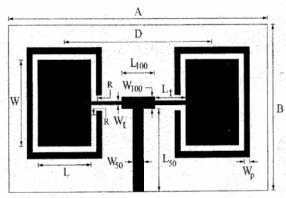
Figure 1 shows the top view geometry of TERMAA comprising of parasitic strip around the radiating patches. The length L and width W of the patch is designed for resonant frequency of 5 GHz, using the equations available for design of rectangular patch [7]. The width of parasitic strip is Wp and is kept away from the side edges of the
patch by a distance R. The gap between the edges of strip and quarter wave transformer is again R. The distance D between the two radiating elements from their centre should be
Figure 1, D is taken as λo/2.33 in order to keep the feed line as compact as possible for minimum feed line loss. Further, when D is less than λo/2.33; it becomes difficult to accommodate the feed arrangement between the array elements. Hence D = λo/2.33 is
treated as optimum in this case. The parallel feed arrangement has wideband performance over series feed and hence selected in this case to excite the array elements of Figure 1. The feed arrangement shown in Figure 1 is a contact feed and has advantage that it can be etched simultaneously along with antenna elements. The parallel feed arrangement of Figure 1 consists of a 50 Ω microstrip feedline of length L50 and width W50 is connected
to 100 Ω microstrip feedline of length L100 and width W100 to form a two way power
divider. A 100 Ω quarter wave matching transformer of length Lt and width Wt is
connected between 100 Ω microstrip feedline and mid point of the radiating elements in
order to ensure perfect impedance matching. The bottom plane of TERMAA is tight ground plane copper shielding. The ground plane shielding of TERMAA is minimized as shown in Figure 2 retaining its top geometry. This antenna is named as modified ground plane two elements rectangular microstrip array antenna (MGTERMAA). The size of copper area on the ground plane is taken as A1×B. Later, the corners of the ground plane
of MGTERMAA are truncated as shown in Figure 3 retaining its top geometry. This antenna is named as corner truncated ground plane two element rectangular microstrip array antenna (CTGTRMAA). The corners are truncated by length Lc and width Wc. The
various antenna parameters of Figure 1 to Figure 3 are given in Table 1.
Figure 2 Ground plane geometry of MGTERMAA
Figure 3 Ground plane geometry of CTGTRMAA
3. EXPERIMENTAL RESULTS
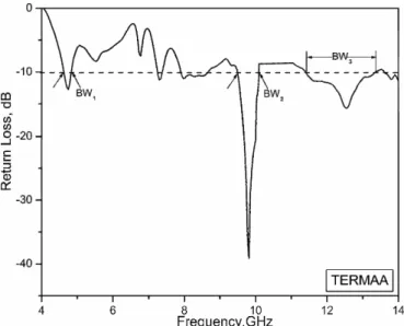
The impedance bandwidth over return loss less than −10 dB of the proposed antennas is measured on Vector Network Analyzer (Rohde & Schwarz, Germany make ZVK model 1127.8651). The variation of return loss versus frequency of TERMAA is as shown in Figure 4. From this figure, it can be seen that the antenna resonates for three band frequencies BW1, BW2, and BW3. The impedance bandwidth of each operating
band is determined by using the equation,
Impedance bandwidth 2 1 c ( ) = f f ×100 % f −
where, f1 and f2 are the lower and upper cut-off frequencies of the band respectively, when its return loss becomes −10 dB and fc is the center frequency between
Figure 4 Variation of return loss verses frequency of TERMAA
The magnitudes of impedance bandwidth BW1, BW2 and BW3 are found to be
5.5, 14.04 and 16.08% respectively. These triple bands are due to the independent resonance of radiating elements and parasitic strip [9-10]. The variation of return loss versus frequency of MGTERMAA is as shown in Figure 5. From this graph, it can be seen that the antenna resonates for four bands of frequencies BW4, BW5, BW6 and BW7
with corresponding magnitudes of impedance bandwidth is found to be 17.22, 14.22, 10.38 and 67.76% respectively. The additional bands between BW4 to BW7 are due to the
effect of modified ground plane in MGTERMAA.
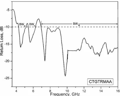
Figure 6 shows the variation of return loss versus frequency of CTGTRMAA. From this figure, it can be seen that the antenna resonates again for triple bands BW8,
BW9 and BW10 with corresponding magnitude of impedance bandwidth is found to be
19.1, 15.43 and 79.23% respectively. It is clear that the two bands BW6 and BW7 of
MGTERMAA as shown in Figure 5 which are close to each other combines together resulting into a single band BW10 as shown in Figure 6. Thus CTGTRMAA enhances the
operating bandwidth of triple band operation.
Figure 6 Variation of return loss verses frequency of CTGTRMAA
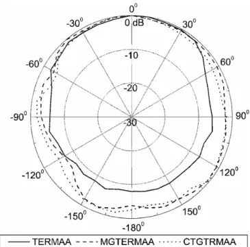
The co-planar radiation pattern of antenna under test (AUT) is measured by connecting a standard pyramidal horn antenna in far field region. The AUT is connected in receiving mode and is kept in phase with respect to transmitting pyramidal horn antenna. The power received by AUT is measured from 00 to 3600 with steps of 100.The typical radiation patterns of TERMAA, MGTERMAA and CTGTRMAA measured at 12.55, 9.81 and 9.81 GHz respectively is as shown in Figure 7. From the figure, it can observe that the patterns are omni directional in nature. Hence the enhancement of impedance bandwidth of triple band operation through CTGTRMAA does not affect the nature of radiation characteristics.
Figure 7 Radiation pattern of TERMAA, MGTERMAA and CTGTRMAA
For the calculation of gain of proposed antennas, the power transmitted ‘Pt’ by
pyramidal horn antenna and power received ‘Pr’ by AUT are measured independently.
With the help of these experimental data, the gain G (dB) of AUT is calculated using the absolute gain method [11],
( )
r(
)
0 t λ P G dB=10 log Gt dB 20 log dB P 4πR − − Where, Gt is the gain of the pyramidal horn antenna and R is the distance between
the transmitting antenna and the AUT. The gains of TERMAA, MGTERMAA and CTGTRMAA are found to be 0.71, 3.60, and 3.90 dB respectively. Hence CTGTRMAA gives highest gain among the proposed antennas.
4. CONCLUSION
From the detailed experimental study, it is concluded that, triple band operation with omni directional radiation pattern of antenna is achieved by designing TERMAA. Further, by minimizing the area of ground plane, quadruple bands are observed. Later, by truncating the corners of the minimized ground plane, the enhancement of impedance bandwidth at each operating bands in the triple band operation is possible without changing the nature of omni directional radiation characteristics. This technique also enhances the gain from 0.71 t0 3.90 dB. The proposed antennas are simple in their
design, fabrication and they use low cost substrate material. The proposed antennas may find applications for microwave systems operating at WLAN (2.4 – 5.2 GHz), HIPERLAN/2 (5.725 – 5.825 GHz) and X to Ku (8 – 18.5 GHz) band of frequencies.
ACKNOWLEDGEMENTS
The authors would like to thank Dept. of Sc. & Tech. (DST), Govt. of India, New Delhi, for sanctioning Network Analyzer to this Department under FIST project.
TABLE 1
Design Parameters of Proposed Antennas
Antenna Dimensions Parameters (cm) Antenna Dimensions Parameters (cm) A 5.00 B 3.50 L 1.41 W 1.86 Lt 0.38 Wt 0.015 L50 1.54 W50 0.32 L100 0.38 W100 0.07 R 0.10 D 2.33 A1 1.16 Lc 0.30 Wc 0.20 λ0 60.00
REFERENCES
1. Wang .W., et. al. (2004), “A dual polarized stacked microstrip antenna sub array for X-band SAR application”, IEEE Antennas and Propag, Soc. Inter. Symp, Vol.2, pp.1603-1606.
2. Waterhouse .R.B and Shuley N.V (1992), “Dual frequency microstrip rectangular patches”, Electron Lett, Vol.28, No.07, pp.606-607.
3. Richards .W.F., et. al. (1985), “Dual-band reactively loaded microstrip antenna”, IEEE Trans Antennas Propag, Vol. 33, No.5, pp.556-560.
4. Wang .J., et. al. (1990), “Multifunctional aperture coupled stack patch antenna”, Electron Lett, Vol.26, No.25, pp.2067-2068.
5. Salvador .C (1995), “Dual frequency planer antennas at S and X bands”, Electron Lett, Vol.31, No.20, pp.1706-1707.
6. Pushpanjali .G.M., et. al. (2008), “Equilateral triangular microstrip array antenna for broad band operation”, Microwave Opt Technol Lett, Vol. 50, No.07, pp.1834-1837.
7. I. J. Bhal and P. Bhartia (1980), “Microstrip Antennas”, Artech House, New Delhi.
8. C. A. Balanis (1982), “Antenna Theory Analysis and Design”, John Wiley & Sons, New York.
9. Rafi .G.Z and Shafai .L (2004), “Wideband V-slotted diamond-shaped microstrip patch antenna”, Electron Lett, Vol.40, No.19, pp.1166-1167.
10.Row .J.S (2005), “Dual-frequency triangular planar inverted-F antenna”, IEEE Trans Antennas Propag, Vol.53, No.2, pp.874-876.
11.Sameena .N.M., et. al. (2009), “A novel slot for enhancing the impedance bandwidth and gain of rectangular microstrip antenna”, Progress In Electromagnetic Research, PIER 11, pp.11-19.