Quantum Circuit Simplification and
Level Compaction
Dmitri Maslov, Gerhard W. Dueck,
Member, IEEE, D. Michael Miller,
Member, IEEE, and Camille Negrevergne
Abstract—Quantum circuits are time-dependent diagrams de-scribing the process of quantum computation. Usually, a quantum algorithm must be mapped into a quantum circuit. Optimal syn-thesis of quantum circuits is intractable, and heuristic methods must be employed. With the use of heuristics, the optimality of circuits is no longer guaranteed. In this paper, we consider a local optimization technique based on templates to simplify and reduce the depth of nonoptimal quantum circuits. We present and analyze templates in the general case and provide particular details for the circuits composed of NOT, CNOT, and controlled-sqrt-of-NOT gates. We apply templates to optimize various common circuits implementing multiple control Toffoli gates and quantum Boolean arithmetic circuits. We also show how templates can be used to compact the number of levels of a quantum circuit. The runtime of our implementation is small, whereas the reduction in the number of quantum gates and number of levels is significant.
Index Terms—Circuit optimization, quantum circuits, time optimization.
I. INTRODUCTION
R
ESEARCH in quantum circuit synthesis is motivated by the growing interest in quantum computation [19] and advances in experimental implementations [4], [7], [8], [25]. In realistic devices, experimental errors and decoherence intro-duce errors during computation. Therefore, to obtain a robust implementation, it is imperative to reduce the number of gates and the overall running time of an algorithm. The latter can be done by parallelizing (compacting levels) the circuit as much as possible.Even for circuits involving only a few variables, it is at present intractable to find an optimal implementation. Thus, a number of heuristic synthesis methods have emerged. Applica-tion of these methods usually results in a nonoptimal circuit, which can be simplified with local optimization techniques. Additionally, some quantum circuits for important classes of functions, such as adders and modular exponentiation, were created and compacted in anad hocmanner [5], [16].
Manuscript received May 14, 2007; revised July 13, 2007 and August 1, 2007. This work was supported by postdoctoral fellowships and discovery grants from the National Sciences and Engineering Research Council of Canada. This paper was presented in part at the 2005 Design, Automation and Test in Europe Conference and Exposition, Munich, Germany, March 2005. This paper was recommended by Associate Editor K. Chakrabarty.
D. Maslov and C. Negrevergne are with the Institute for Quantum Com-puting, University of Waterloo, Waterloo, ON N2L 3G1, Canada (e-mail: [email protected]).
G. W. Dueck is with the Faculty of Computer Science, University of New Brunswick, Fredericton, NB E3B 5A3, Canada.
D. M. Miller is with the Department of Computer Science, University of Victoria, Victoria, BC V8W 3P6, Canada.
Digital Object Identifier 10.1109/TCAD.2007.911334
Local optimization has only recently been considered as a possible tool for the gate count reduction in quantum [13] and reversible (quantum Boolean) circuits [10]. Some quantum circuit identities that could be used for circuit simplification can be found in [19]. While these provide several rewriting rules with no ready-to-use algorithm for their application, there is clearly a benefit in a systematic approach using templates that are discussed in this paper. A somewhat different approach for local optimization of reversible NOT–CNOT–Toffoli circuits was applied for the simplification of random reversible circuits in [22]. That approach and our template method are difficult to compare as they have been applied to different types of circuits with different metrics for the circuit cost.
So far, computer-aided design tool engineers have spent little effort on minimizing the number of logic levels in quantum circuits. However, this allows a shorter running time as it results in parallelization of the algorithm. More importantly, in the popular quantum error model where errors appear randomly with time, a parallel circuit helps reduce the errors. For instance, it may be possible to use a smaller number of error correction code concatenations (each of which is a very expensive opera-tion, requiring at least triple the number of physical qubits [19]) if the circuit is well parallelized. To the best of our knowledge, all of the presently existing quantum circuits were at best compacted in an ad hoc fashion. In this paper, we automate level compaction using templates.
Methods based on templates have been considered for Toffoli reversible network simplification [14]. In this paper, we revisit the definition of templates and show how they can be applied in the quantum case as a systematic basis for quantum circuit simplification and level compaction.
This paper discusses circuit parallelization, reports the im-proved results based on a new and significantly more efficient implementation, and includes extensive testing results, as well as certain new discussions. It is organized as follows: We start with a brief overview of the necessary background in Section II. In Section III, we define the templates and discuss some of their properties. We present a method to identify the templates and describe two algorithms, one to reduce the cost and the other to reduce the number of logic levels of quantum circuits, in Section IV. We next choose a specific quantum gate library and illustrate the effectiveness of the aforementioned approach. Section V presents a set of small quantum templates for NOT, CNOT, and controlled-sqrt-of-NOT (NCV) gates and illustrates the algorithms. The benchmark results presented in Section VI are divided into two parts. We first optimize quantum im-plementations of the multiple control Toffoli gates (including multiple control Toffoli gates with negative controls) and then
consider optimization of some NOT–CNOT–Toffoli circuits available through the existing relevant literature. Discussion of future work and concluding remarks are found in Sections VII and VIII.
II. BACKGROUND
We present a short review of the basic concepts of quantum computation necessary for this paper. An in-depth coverage can be found in [19].
The state of a single qubit is a linear combinationα|0+
β|1 (also written as a vector(α, β)) in the basis {|0,|1},
where αand β are complex numbers, called the amplitudes, and|α|2+|β|2= 1. Real numbers|α|2and|β|2represent the probabilities p and q of reading the logic states |0 and |1
upon measurement. The state of a quantum system withn >1
qubits is given by an element of the tensor product of the single state spaces and can be represented as a normalized vector of length 2n, called the state vector. Quantum system evolution
allows changes of the state vector through its multiplication by
2n×2nunitary matrices, called gates.
The preceding paragraph models how a transformation can be performed, but it does not indicate how to identify the unitary operations that compose the transformation or how to implement them. Efficiency of the physical implementation depends on the system’s Hamiltonian and the details of different systems (and associated gate costs) are not a focus of this paper. Typically, certain primitive gates are used as elementary building blocks [2], [9]. Among these are as follows:
1) NOT (x→x¯) and CNOT ((x, y)→(x, x⊕y)) gates, wherex,y∈ {0,1}and⊕is addition modulo 2;
2) a Hadamard gate, which is defined by H = (1/√2) 1 1 1 −1 ;
3) a controlled-V gate, which, depending on the value on its control qubit, changes the value on the target qubit using the transformation given by the matrixV= (i+ 1/2) 1 −i −i 1 ;
4) a controlled-V+ gate, which, depending on the value of its control qubit, changes the value on the target qubit using the transformationV†=V−1;
5) rotation gates Ra(γ), where γ∈[0,2π] and a∈
{x, y, z}.
We shall write G−1 to denote the gate implementing the inverse function of the function realized by gateG. In context, we will useGto mean a gate or the transformation matrix for that gate. The circuit diagrams are built in the popular notations, such as those used in [19]. In short, horizontal “wires” represent a single qubit each; the time in the circuit diagrams is prop-agated from left to right; (positive) gate controls are depicted with•; targets appear as⊕for NOT and CNOT gates, V for a controlled-V gate, and V+ for a controlled-V+ gate, with vertical lines joining the control(s) of a gate with its target.
The principle of the optimization method is to associate a cost to each of these elementary gates and lower the overall circuit cost by reducing the number of high-cost gates. The
cost definition must reflect how difficult it is to implement the gate and, therefore, will depend on the details of the physical device considered to implement the circuit. For example, for nuclear magnetic resonance (NMR) techniques, the cost of the gate must take into account the number of RF pulses, as well as the duration of the interaction periods necessary to implement the gate [4]. In a setting guided by the Ising-type Hamiltonian in a weak coupling regime (such as liquid NMR [4] and superconductors [6]), a controlled-V and its complex conjugate must be associated with approximately half the cost of a CNOT gate each. Thus, controlled-V and controlled-V+ are not at all complex gates. Two qubit gate implementation costs in any given Hamiltonian can be found using the technique discussed in [26].
The Toffoli gate [24] and its generalization with more than two controls serve as a good basis for synthesis purposes. Indeed, every reversible (quantum Boolean) function can be realized as a cascade of multiple control Toffoli gates [2], [14]. The multiple control Toffoli gate flips the target bit if the control bits are in a given Boolean state. Unfortunately, the multi-ple control Toffoli gates (including the original Toffoli gate [24]) are not simple transformations in quantum technologies. They require a number of elementary quantum operations, and Toffoli gates with a large number of controls can be quite costly [2]. However, they can be implemented using circuits composed of three-qubit Toffoli gates [2]. Finally, the three-qubit Toffoli gate can be constructed from a set of gates, which includes the NOT, CNOT, controlled-V, and controlled-V+. We therefore consider all these gates in Section V when we search for tem-plates to simplify the best known quantum circuits implement-ing large Toffoli gates and reversible functions. In addition, any unitary can be synthesized as a generic quantum circuit through exploring the properties of matrix decompositions [2], [18], [21]. Wedo notconsider those circuits here, but we point out that our circuit simplification techniques are applicable in any of the aforementioned cases.
III. TEMPLATES: DEFINITION
To decrease the cost of a circuit, the basic idea is to replace a subcircuit with an equivalent one that has a lower cost. We will call this procedure the application of a rewriting rule. Some problems arise with this technique.
1) In general, even for simple circuits, if rotation gates with any parameter γ are allowed, the number of possible rewriting rules is infinite.
2) Equivalent circuits with the same cost might require different sets of rewriting rules to be simplified.
3) A subcircuit may be rewritten in another form having the same cost, but this second form could allow extra simplifications on the circuit using other rewriting rules. One of the problems arising from these considerations is to minimize the number of rewriting rules by keeping only the “essential” ones. To address these issues, we introduce the notion of templates that will be applicable to all quantum gate libraries and discuss the algorithms for quantum gate reduction and level compaction.
Definition: A sizemtemplate is a sequence ofmgates that implements the identity operator and that satisfies the following constraint: any template of sizemmust be independent of all templates of smaller or equal size, i.e., for a given templateT of sizem, no application of any set of templates of smaller or equal size can decrease the number of gates inT or make it equal to another template.
A template can be seen as a generalization of the rewriting rules since rewriting rules can be derived from it. For example, forward application of the template G0G1· · ·Gm−1=I allows us to find a rewriting rule of the form GiG(i+1) modm· · ·G(i+p−1) modm→ G−(i1−1) modm
G−(i1−2) modm· · ·G−(i1+p) modm, where 0≤i, p≤m−1. Similarly,backward applicationof the template is a rewriting rule of the form G−i1G−(i1−1) modm· · ·G−(i1−k+1) modm→ G(i+1) modmG(i+2) modm· · ·G(i−k) modm, where 0≤i,
p≤m−1.
A template application requires that the inverse of each gate be available. Clearly, templates are a more compact way of representing nonredundant rewriting rules as they are capable of storing up to2m2rewriting rules.
See the Appendix for a proof of the effect of the forward and backward applications of templates.
IV. TEMPLATES: APPLICATION
In this section, we present a method to find and classify the templates and introduce two algorithms using them. One is an algorithm for quantum cost reduction, and the other is for quantum circuit level compaction, both based on the notion of the templates.
A. Template Identification
First, we find all templates of the form AA−1 (length 2), which we callgate-inverse rules. This is straightforward, since every self-inverse gateAforms the templateAAand every pair of gatesAandB, whereB=A−1, forms one template of the formAB.
Subsequent templates are found by identifying increasingly longer sequences of gates that realize the identity function and that cannot be reduced by other available templates.
Templates of the formABAB(length 4), withA=A−1and B=B−1applied for parameterp= 2, result in construction of the rewriting rulesAB→BA andBA→AB. That is, they define the conditions under which two gates commute. We call such templatesmoving rulesand apply them to move gates to form matches, leading to reduction via other templates.
For applications, we suggest seeking a complete classifica-tion of the templates of small size and then supplementing those by a set of templates that appear to be useful when a specific synthesis procedure is applied. For example, if a synthesis procedure (or the circuit types one considers) tends to use a specific type of subcircuit of costµ, which is neither optimal (assume an optimal cost ofν) nor can be simplified by a small-size complete set of templates, a template with a total costµ+νcan be created (followed by a generalization process when and if needed). In this paper, we do not construct any of
these supplementary-type templates since we apply templates to the circuits from different authors obtained from different synthesis procedures.
B. Cost Reduction
In this section, we present an algorithm to reduce thegeneric quantum circuit cost using the templates. To apply the algo-rithms to aspecificphysical implementation, we only need to choose a relevant cost definition.
Input:A quantum circuit specification, i.e., a sequence of gatesC1C2· · ·Cn.
Output:A quantum circuit computing the same function as the input circuit but having a possibly lesser cost.
Algorithm:
1. Let Ck be the start gate in the circuit for a potential
template match. Initially,k= 2.
2. We attempt to match the templates in the order of size (excluding the moving rules). The attempt to match to a sizem templateG0G1· · ·Gm−1proceeds as follows:
a) Forward matching: Apply the moving rules to arrange the gates precedingCk to be able to match them with
the given sizemtemplate. At this step, we determine pair(j, p)
such thatCk−i=G(j+i) modm,0≤i < p. When suchjandp
are found, gatesCk−p−1,Ck−p−2, . . . , Ck can be replaced by
the sequence G−1
(j+p+i) modm, 0≤i < m−p. Substitution is
done if it is beneficial from the point of view of the overall circuit cost reduction.
b) Backward matching: To backward match a size m template, the same procedure applies with the following matching condition: Ck−i=G(−j1−i) modm, 0≤i < p. Then,
gatesCk−p−1,Ck−p−2, . . . , Ckcan be replaced by the sequence
G(j+p−i) modm,0≤i < m−p. The decision to replace or not
is based on a chosen circuit cost metric.
3. We propagate this procedure through the circuit. • If a template substitution was made, thenk is set to the index of the leftmost gate substituted, and we repeat step 2. • Otherwise, if we can, increment k by 1 and repeat step 2. If we cannot becauseCkis already the rightmost gate in
the circuit, the algorithm terminates.
The gate replacement at step 2 is performed when it is beneficial to do such replacement, i.e., when the total circuit cost is reduced. This imposes extra constraints on the parameter pdepending on the exact cost definition. For instance, with a simple gate count cost metric,pmust be greater thanm/2. If many pairs (j, p)are found, the one associated to the biggest cost reduction is chosen for the gate substitution. However, even if the total cost after template application stays the same (for a simple gate count cost metric, this means applying an even-size template by replacing its half with another half, i.e., for even mandp=m/2), the substitution can be beneficial as the new circuit arrangement may allow other cost-reducing template applications. We take this into account by allowing such “cost-retaining” template applications as long ask < F lag(kis the value of the subscript ofCk), with theF laginitially set to 0.
to the currentk value, and after each cost-reducing template application, theF lagis set back to 0. This guarantees that the cost reduction algorithm will not run into an infinite loop while allowing a cost-retaining template application.
In Section V, we illustrate how the templates are applied to reduce the gate count.
C. Level Compaction
We next suggest a greedy algorithm for quantum circuit level compaction employing templates. A level is defined as a subsequence of commuting gates that can be applied in paral-lel. Level compaction helps increase the parallelization of the circuit implementation and, therefore, not only optimizes the runtime of the circuit but also helps decrease the decoherence effects by shortening the overall execution time.1Forsimplicity of the algorithm description, we assume that all gates have the same duration; therefore, the execution time of a level is equal to a single gate duration. We also assume that neighboring gates operating on disjoint qubit subsets can always be applied in par-allel, which is a common assumption for quantum technologies.
Input: A quantum circuit specification, i.e., a cascade of gatesC1C2· · ·Cn.
Output: A reorganized circuit with possibly fewer levels, computing the same function as the input circuit.
Algorithm: The principle is to assign a specific level to each gate.
1. Initially, all gates in the circuit have an undefined level, i= 1, and we defineQlevelias an empty set.
2. ConsiderCj as the leftmost gate that has not yet been
assigned a level. Assign levelito it.
3. Until each gateCk, i.e., right ofCj, is considered:
a) If gateCk does not share common qubits with any
of the gates in levelQleveliand if it can be moved left (using
the moving rules) until it is adjacent to the leftmost gate with leveli, then assign levelito it.
b) If it is not possible to move gateCkjust as described,
then apply templates using the aforementioned algorithm, with Ck as the start gate and considering only those gates whose
level has not yet been assigned. Only templates with an even number m of gates are applied, and only substitutions of m/2 for m/2gates are made. Such substitution may allow a
1For instance, a liquid NMR circuit with a high degree of parallelization
of single qubit rotations and ZZ gates will be significantly shorter than its unparalleled version. Indeed, single qubit rotations on homonuclear spins are usually implemented by selective soft pulses sequentially sent to act on each spin. Nevertheless, if we want to act on all homonuclear spins in parallel, it is possible to use a single broad-band short pulse [4]. As for heteronuclear spins, modern spectrometers have several channels that can be simultaneously used. Therefore, one can rotate heteronuclear spins in parallel by pulsing on them in parallel. More importantly, in a typical NMR system, the main time-consuming gates are the interaction gates (ZZ gates). Because all the couplings are always on in a molecule, ZZ gates naturally occur in parallel in the circuit. To apply a ZZ gate to a given pair of qubits, one needs to use refocusing techniques [4] involving pulses and delays to cancel all the ZZ interactions but the desired one. Therefore, in most of the cases, regrouping the ZZ gates will allow one to optimize the refocusing scheme and reduce the overall number of required delays. In particular, the refocusing scheme exists for any subset of nonintersecting gates, which is defined as a single logic level in this paper [11].
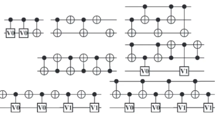
Fig. 1. Quantum templates other than the gate-inverse and moving rules. Each of these circuits implements the identity.
gate (possibly with movement) to subsequently be assigned to leveli.
4. If there are still gates that have not assigned a level, then add 1 toi(the number of levels), consider a new emptyQleveli,
and repeat steps 2 and 3.
At this stage of development, the level compaction algorithm is greedy. We expect that it can likely be improved. However, our tests have shown that its current performance has already improved the relevant quantum circuits.
V. QUANTUMNCV TEMPLATES
We now present a set of quantum templates based on the NCV gate library.
1) Thegate-inverse rules: NOT and CNOT are self-inverses, and controlled-V and controlled-V+ are the inverses of each other.
2) Themoving rule(replaceABwithBA): assuming gate Ahas control setCA(CAis an empty set in the case of an
uncontrolled gate) and targetTA, and gateB has control
setCBand targetTB, these two gates form a moving rule
if, and only if,TA⊆CBandTB⊆CA.
3) Larger templates: all other templates that we have iden-tified are shown in Fig. 1, whereV (alternatively V+) is substituted for all occurrences of V0, and V+ (alter-nativelyV) is substituted for all occurrences ofV1, i.e., the substitution is consistent and distinct forV0andV1. The templates reported here were found by inspection. We are currently developing a program to systematically find larger templates and to verify the completeness of the current set.
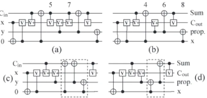
To illustrate how templates are applied, consider the quantum circuit for the three-input full adder with ten gates from [9]. The circuit is built on four qubits as the three-input adder must be extended to a four-variable reversible function. Note that the original circuit presented in [9] gives 1111 as the output for the input pattern 0100 instead of the expected 1011. The circuit shown in Fig. 2(a) corrects this.
In the circuit in Fig. 2(a), gates 5 and 7 (counting from the left) can be moved together and form a gate-inverse pair. We move them together and delete them by applying the gate-inverse rule. This results in the circuit illustrated in Fig. 2(b).
Fig. 2. Simplification of a ten-gate quantum network for the three-qubit full adder.
Next, we notice that gates 4, 6, and 8 in this circuit can also be brought together (gates 4 and 8 should be moved toward gate 6). Fig. 2(c) shows the three gates brought together, and Fig. 2(d) illustrates the resulting circuit after the size-5 template is applied.
The circuit that we found using template simplification [Fig. 2(d)] is equivalent to the optimal circuit (for a given input-to-output assignment) reported in [9]. It took our program <0.001 second (elapsed time on a 1.8-GHz Athlon XP2400+ machine with a 512-MB RAM running Windows) to simplify the circuit in Fig. 2(a) into the circuit in Fig. 2(d). The time reported in [9] to synthesize such a circuit is seven hours. This example clearly shows that templates are useful and effective.
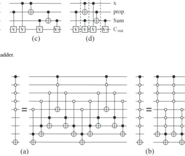
A likely optimal quantum circuit for the three-input full adder can be constructed from its well-known reversible im-plementation, as illustrated in Fig. 3(a). We first substitute quantum circuits for the Peres gates [20], each of which is a Toffoli–CNOT pair [see Fig. 3(b)]. We then apply the templates. In this case, gates 4 and 6 can be moved together and match the gate-inverse rule. Thus, they are both deleted, leading to the circuit in Fig. 3(c). Finally, we apply the level compactor, and the circuit is transformed into the one illustrated in Fig. 3(d) (different logic levels are separated by dashed vertical lines). The number of levels in the compacted circuit is four, and this is a minimum because there are four gates with targets on qubit
0−Cout.
A. Other Templates
It is possible to construct the templates in other gate li-braries and then use the discussed cost reduction and level compaction algorithms verbatim. Constructing the templates for the finite (those seem to be more physical) gate libraries may be reduced to finding the rewriting rules by hand and generalizing them into the templates, or running a computer search. A parameterization/classification of the templates in this case may be helpful. However, in the libraries with an infinite number of gates, a classification is necessary. We suggest that each template (template class) be written in the circuit form and followed by an algebraic expression, conditional upon which the template applies. For example, in the library with single qubit rotations and CNOT gates, the following template might be constructed:Ra(α)Ra(β)Ra(γ), whereα+
β+γ= 0. Application of such a template can be thought of as finding two single qubit rotations about the same axis
(not necessarily the conventional X,Y, orZ, but a possible combination of them), which can be commuted until they are neighbors, and then, they are replaced by a single cumulative rotation. Another example of a template for this gate library could be RX(α)RZ(−π/2)RY(α)RZ(π/2), which could be
used to replace some three gates with one, or, for instance, eliminate all RX gates from a given circuit. In the gate
li-brary with controlled gates, the following template is pos-sible: CU(b, c)CN OT(a, b)CU†(b, c)CN OT(a, b)CU(a, c), conditional upon gateCUbeing a self-inverse. This template is a generalization of the one used in this paper (third template in Fig. 1), but it captures an infinite number of the rewriting rules. Other templates are possible and depend on the considered gate base. The discussed examples are not intended to be treated as a complete review of the possible templates, but rather an illustration of what kind of templates may be constructed.
VI. NUMERICALRESULTS
Reversible logic and quantum arithmetic circuits are often specified with NOT, CNOT, and Toffoli gates [2], [5], [15], [16], [19], rather than with gates from the NCV set. Circuits with multiple control Toffoli gates have been extensively studied, and synthesis procedures exist. To process these circuits, we need to transform every Toffoli gate into a circuit with NOT, CNOT, controlled-V, and controlled-V+ gates. We use the circuit in Fig. 4(a) for this purpose. Due to the symmetry properties of the NCV and Toffoli gates (interchangeability of the controlled-V and controlled-V+ gates in quantum NCV circuits for reversible functions [17], symmetry of Toffoli gate controls, and self-inverse property of the Toffoli gate), there exist eight distinct, but equivalent, NCV circuits for a Toffoli gate. In our procedure, we use only two of them, i.e., the circuit in Fig. 4(a) and its inverse, and keep the one resulting in a better circuit simplification. Empirical tests have shown that the use of the other six transformations will not yield any new improvements.
A. Multiple Control Toffoli Gate Simulations
Multiple control Toffoli gates and their variants with negated controls are a popular basis for the synthesis of reversible circuits and are often used to construct quantum circuits. For instance, multiple control Toffoli gates are used in quantum error correcting circuits right after the syndrome was found to correct errors [19]. Even more importantly, multiple control Toffoli gates are at the heart of the amplitude amplification technique [3] that is often considered as a separate class of quantum algorithms, of which there are only a few. Thus, multiple control Toffoli gates are indispensable for quantum computations, and it is very important to have efficient quantum circuits for them. Implementations of multiple control Toffoli gates were studied in [1] and [2]. In the following, we simplify and compact the levels in the multiple Toffoli gate circuits described in [1] and [2] using our template-based algorithms. We compare our results to those initially presented. Table I summarizes the results.
Fig. 3. Simplification of an eight-gate quantum circuit for the three-qubit full adder.
Fig. 4. Optimal NCV circuits for the (A) three-qubit Toffoli gate [19] and (B) three-qubit Toffoli gate, with a single negative control (b) [17].
TABLE I
SIMPLIFICATION OF THEMULTIPLECONTROLTOFFOLIGATE IMPLEMENTATIONS BYBARENCOet al.[2]ANDASANO ANDISHII[1]. THE RESULTSAREGROUPEDINTOTWOTABLESACCORDING TO THESOURCE OF THEINITIALCIRCUIT. COLUMNS“Size”AND“Ancilla” SHOW THESIZE (n-QUBITGATE)OF THEMULTIPLECONTROLTOFFOLIGATE AND THE NUMBER OFANCILLAQUBITSASSOCIATEDWITH THEIMPLEMENTATION OFTHISGATE, RESPECTIVELY. COLUMNS“[citation] GC” AND“[citation]
D” PRESENT THEGATECOUNT(GC)IN THEBESTREPORTEDQUANTUM NCV CIRCUITTAKENFROM THEAPPROPRIATESOURCEINDICATED
IN“[citation]”AND THECORRESPONDINGCIRCUITDEPTHD, RESPECTIVELY. WESHOW THEGATECOUNTS ANDCIRCUITDEPTH FOROUROPTIMIZEDIMPLEMENTATIONS INCOLUMNS“Opt-d GC”AND
“Opt-dD,” RESPECTIVELY. WHENEVERCOLUMNS“[citation]D”AND “Opt-dD” ARENOTPRESENT, THISMEANSTH AT THEDEPTH EQUALS TO THENUMBER OFGATESBOTH IN THECIRCUITBEFORE
OPTIMIZATION AND IN THECIRCUITAFTEROPTIMIZATION
The results in Table I show that the set of multiple control Toffoli gates of sizen realizations with gate count of 20n−
60 [2, Lemma 7.2] is always simplified to the circuits with
12n−34gates. Based on the regularity and predictability of this simplification, we conjecture that this will always be the case. Furthermore, our experiment showed that asymptotically, we obtain a 40% reduction in the number of gates and in the number of logic levels required in simulation of the multiple control Toffoli gates. Similarly, circuits for multiple control Toffoli gates with5(n−2)2gates and depth of10n−20seem to always simplify to the circuits with3.75(n−2)2 gates and depth of7.5n−10.
Multiple control Toffoli gates can be implemented with a single auxiliary qubit, as discussed in [2, Corollary 7.4]. Using
Fig. 5. Simulations of a multiple control Toffoli gate with some but not all negations illustrated for the maximum number of possible negative controls [2]. (a) Usingn−3auxiliary qubits. (b) Using a single auxiliary qubit.
our tool, we achieved anupper boundof24n−88(forn >5) for the number of gates, and the number of levels required in multiple control Toffoli gate simulations with a single auxiliary qubit using the decomposition from [2, Lemma 7.2]. We stress that the aforementioned formulas are upper boundssince we did not yet apply our techniques to simplify such circuits. There must be a clever approach in which both types ofn−3
auxiliary qubit decompositions are used in the construction due to [2, Corollary 7.4], and depending on whether the final gate count or depth needs to be optimized, the choice for a particular multiple Toffoli gate substitution may vary.
Multiple control Toffoli gates with negations may also be useful in some applications. A canonical implementation of such gates [19, Fig. 4.11 and 4.12] assumes a logic layer of NOT gates preparing the literals in the right polarity, followed by a multiple control Toffoli gate with all positive controls and a level of NOT gates returning the values of literals to the positive polarity. This makes multiple control Toffoli gates with negative controls marginally more expensive than the multiple control Toffoli gates with only positive controls. In the following, we show that a multiple control Toffoli gate with some but not all negative controls can be implemented with the same cost as a multiple control Toffoli gate of the same size but with only positive controls.
Given that the three-qubit Toffoli gate with a single negated control can be implemented with the same (minimal) number of gates as a three-qubit Toffoli gate with positive controls [17] [see Fig. 4(b)], such a gate can be used in the circuit proposed by Barencoet al.[2] to implement multiple control Toffoli gates with some but not all negations with no cost overhead. Such a simulation is illustrated in Fig. 5(a).
Furthermore, such multiple control Toffoli gates with some but not all negative control implementations [2, Lemma 7.2] rely on a similar strategy to simplify and compact the levels
as the one used for a multiple control Toffoli gate with all positive controls. Therefore, each multiple control Toffoli gate with some but not all negative controls can be implemented with(n−3) auxiliary qubits,12n−34CNOT, controlled-V and controlled-V+ gates, and 12n−34logic levels (n >3). Using the simulation illustrated in Fig. 5(b), one can construct a multiple control Toffoli gate with some but not all negations and requiring a single auxiliary qubit with no more than24n−88
gates and the same number of logic levels (forn >5).
Implementation of a multiple control Toffoli gate with all negations that uses(n−3)auxiliary qubits will require two ex-tra NOT gates; however, the number of levels will not increase. Similarly, a multiple control Toffoli gate with all negation simulation with a single auxiliary qubit will require four extra NOT gates with no increase in the number of logic levels (upper bound).
A similar argument holds in the case of the decomposition from [1], but we do not discuss this here. Rather, we move on to considering other types of circuits.
B. Benchmark Circuits
Here, we present the results of the application of the tem-plates to a number of quantum circuits implementing various reversible Boolean and quantum arithmetic functions that can be found in the literature. Many reversible/quantum circuits have constant input values and garbage outputs. This typically occurs when a nonreversible function is mapped to a reversible one prior to synthesis as a reversible circuit. In such cases, extra simplifications at the extremities of the circuit can be performed.
1) If a gate whose control is an input constant can be moved to the beginning of the circuit, then depending on the constant input controlling the gate being 0 or 1, the gate can be either deleted or uncontrolled (assuming an uncontrolled gate has a lesser cost).
2) If a gate with the target on a garbage output can be moved to the end, we can delete it as we are not interested with the value of the garbage output.
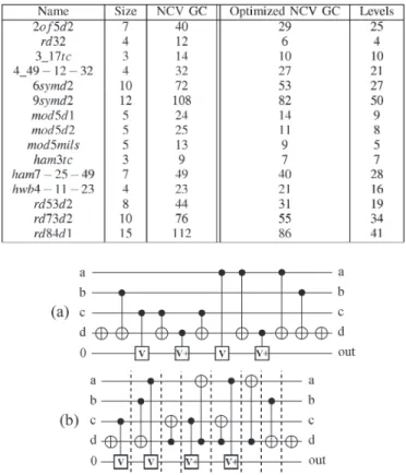
We took the circuits from [15], which are composed of NOT, CNOT, and Toffoli gates, and compared their quantum realization costs (defined as NCV gate count) before and after applying the templates. We also compacted the levels in the simplified circuits and reported the number of obtained levels. Since [15] do not compact the levels in their circuits, we have no comparisons for the number of levels. Table II summarizes the results.
Let us describe the simplification procedure for one of these benchmark circuits, i.e., the five-qubit oracle functionmod5. It leaves the first four inputs unchanged and inverts the last one if, and only if, the first four represent an integer divisible by five. We first found a Toffoli gate realization (circuitmod5mils in Table II). We then applied the previously described template-based optimization techniques. The resulting circuit is illus-trated in Fig. 6(a). If the inputs are not required to be passed through unchanged, the last three gates may be dropped. We next applied the level compaction algorithm. The compacted version of the circuit in Fig. 6(a) is illustrated in Fig. 6(b).
TABLE II
SIMPLIFICATION OF THEBENCHMARKCIRCUITSFROM[15]. CIRCUIT NAMEAPPEARS INCOLUMN“Name”ANDISDIRECTLYTAKENFROM [15]. “Size” INDICATES THENUMBER OFQUBITS IN THECIRCUIT. “NCV GC” LISTS THEQUANTUMNCV GATECOUNTWHEN THETOFFOLIGATES
IN THECORRESPONDINGCIRCUITARESUBSTITUTEDWITHTHEIR QUANTUMIMPLEMENTATIONS. “Optimized NCV GC”AND“Levels” SHOW
THEQUANTUMGATECOUNT AND THENUMBER OFLOGICLEVELS, RESPECTIVELY, AFTERREVERSIBLEGATESARESUBSTITUTEDWITH
THEIRQUANTUMCIRCUITS AND THERESULTINGCIRCUITISRUN THROUGH THETEMPLATESIMPLIFICATION ANDTHEN THELEVEL COMPACTIONPROCESSES. WEDONOTREPORT THERUNTIMES IN
THISTABLEBECAUSEALLCIRCUITSWEREALMOST INSTANTANEOUSLYCOMPUTED
Fig. 6. Circuit for the oraclemod5.
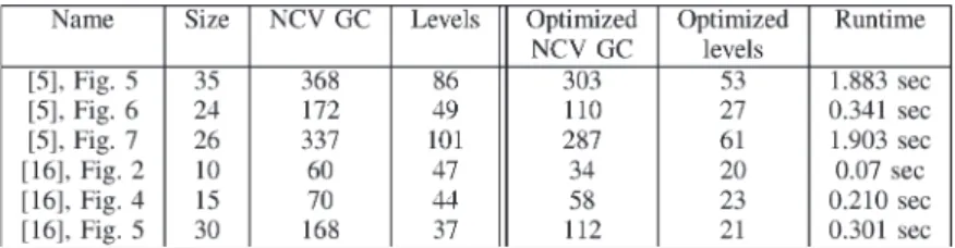
Note how the level compactor changes the form of the circuit to allow fewer levels. This happens when even-size templates are applied to change the form of the circuit to facilitate further level compaction. Unless this is done, the circuit in Fig. 6(a) cannot be compacted to have less than ten logic levels. This is because qubit dis used ten times as a control/target. If the inputs need not be recovered, the depth of such computation is only five logic levels, and the number of required gates is nine. Finally, we applied the simplification procedure to some leveled quantum circuits for the adder, comparator, and modular exponentiation type functions (the latter is an important part of the Shor’s factoring algorithm) reported in [5] and [16]. We took their circuits, substituted quantum implementations of the Toffoli gates where needed, simplified them, and compacted the levels (treating each circuit as nonleveled). In the circuit with Fredkin gates [16, Fig. 4], we used CNOT–Toffoli–CNOT decomposition of the Fredkin gate, and in the circuit with single negative control Toffoli gates [16, Fig. 5], we used the circuit in Fig. 4(b). The results are reported for the three circuits that can be found in [5] and the three circuits from [16] (Table III).
TABLE III
SIMPLIFICATION OF THEBENCHMARKSFROM[5]AND[16]. “Name” SHOWSWHERE THEINITIALCIRCUITCAN BEFOUND, “Size” LISTS THENUMBER OFQUBITSUSED, “NCV GC” LISTS THENUMBER OFNCV GATESREQUIRED,AND“Levels” SHOWS THENUMBER OFLEVELS(EACHLEVEL
WITH ATOFFOLIGATECONSIDERED TOHAVE AWIDTH OF5). OURRESULTS FOR THENUMBER OFGATES AND THENUMBER OFLEVELS ARELISTED INCOLUMNS“Optimized NCV GC”AND“Optimized levels.” THEFINALCOLUMNPRESENTS THETOTALRUNTIME
(ELAPSEDTIME) REQUIRED BYOURSOFTWARE TOCOMPLETE THECIRCUITSIMPLIFICATION ANDCOMPACT THELEVELS WHENRUN ON ANATHLONXP2400+ WITH A512-MB RAM MACHINEUNDERWINDOWS
VII. FUTUREWORK
There are several possibilities to improve our simplification approach. We are interested in developing a smart automated procedure for substituting quantum circuits for multiple con-trol Toffoli gates. The search for the new templates can be accomplished by finding all identities of the given size and applying templates to simplify them. All identities that do not simplify are the new templates. Such a search method is also suitable for proving the completeness of the set of the templates found.
As far as level compaction is concerned, we presented a very simple and greedy algorithm. We expect that our results for the number of levels can be improved using a smarter level compaction algorithm. However, we believe that the templates could still serve as an efficient core for such an improved level compactor.
Finally, we are interested in extending the experimental results of the template application to other sets of quantum gates, including rotation gates and elementary pulses (NMR quantum technology; this will be a technology-specific opti-mization), and accounting for different architectures (which should be straightforward since each undesirable gate can be punished with a high cost). Since the template definition is only based on the properties of matrix multiplication, they can be applied inany quantum gate library and foranycost metric.
VIII. CONCLUSION
We have introduced quantum templates and demonstrated how they can be applied for quantum circuit simplification and level compaction. Templates can be developed for any type of quantum circuit and can be applied for various cost metrics (e.g., simple gate count, weighted gate count, and nonlinear metrics). We implemented our algorithms in C++ and demonstrated the effectiveness of our approach using a variety of previously published circuits. In our tests, we first target gate count minimization and then compact the logic levels in the simplified circuit. In particular, we reduced the sizes and number of logic levels in the best known multiple control Toffoli gate quantum realizations (including multiple control Toffoli gates with negative controls) and in a number of arithmetic quantum circuits presented by previous authors.
APPENDIX
The consistency of the template definition is based on four lemmas.
Lemma 1: For any circuitG0G1· · ·Gm−1realizing a quan-tum functionf, the circuitG−m1−1Gm−1−2· · ·G−01is a realization forf−1.
Proof: Lemma 1 follows from the properties of matrix
multiplication operation.
Lemma 2: For any rewriting rule G1G2· · ·Gk→
Gk+1Gk+2· · ·Gk+s, its gates satisfy G1G2· · ·GkG−k+1s
G−k+1s−1· · ·G−k+11 =I, where I denotes the identity matrix (transformation).
Proof: The following set of equalities constructed using the ruleGG−1=Ifor a single gateGproves Lemma 2:
G1G2· · ·Gk =Gk+1Gk+2· · ·Gk+s G1G2· · ·GkG−k+1sG−k+1s−1· · ·G−k+11 =Gk+1Gk+2· · ·Gk+sGk−+1sG−k+1s−1· · ·G−k+11 G1G2· · ·GkG−k+1sG−k+1s−1· · ·G−k+11 =I.
Lemma 3: For an identityG0G1· · ·Gm−1and any parame-terp,0≤p≤m−1,G0G1· · ·Gp−1→G−m1−1Gm−1−2· · ·G−p1
is a rewriting rule.
Proof: The proof of Lemma 3 follows from Lemma 2 by renaming the subscripts and listing the equalities in reverse
order.
Lemma 4: If G0G1· · ·Gm−1=I, then G1· · ·Gm−1 G0=I.
Proof: The following proves Lemma 4: G0G1· · ·Gm−1=I G−01G0G1· · ·Gm−1=G−01I G1· · ·Gm−1=G−01 G1· · ·Gm−1G0=G−01G0 G1· · ·Gm−1G0=I.
REFERENCES
[1] M. Asano and C. Ishii,New Structural Quantum Circuit Simulating a Toffoli Gate, 2005. quant-ph/0512016.
[2] A. Barenco, C. H. Bennett, R. Cleve, D. P. DiVinchenzo, N. Margolus, P. Shor, T. Sleator, J. A. Smolin, and H. Weinfurter, “Elementary gates for quantum computation,”Phys. Rev. A, Gen. Phys., vol. 52, no. 5, pp. 3457– 3467, Nov. 1995.
[3] G. Brassard, P. Høyer, M. Mosca, and A. Tapp,Quantum Amplitude Amplification and Estimation, 2000. quant-ph/0005055.
[4] D. G. Cory, R. Laflamme, E. Knill, L. Viola, T. F. Havel, N. Boulant, G. Boutis, E. Fortunato, S. Lloyd, R. Martinez, C. Negrevergne, M. Pravia, Y. Sharf, G. Teklemariam, Y. S. Weinstein, and W. H. Zurek,NMR Based Quantum Information Processing: Achievements and Prospects, 2000. quant-ph/0004104.
[5] T. G. Draper, S. A. Kutin, E. M. Rains, and K. M. Svore,A Logarithmic-Depth Quantum Carry-Lookahead Adder, 2004. quant-ph/0406142. [6] M. R. Geller, E. J. Pritchett, A. T. Sornborger, and F. K. Wilhelm,
Quantum Computing With Superconductors I: Architectures, 2006. quant-ph/0603224.
[7] H. Häffner, W. Hänsel, C. F. Roos, J. Benhelm, D. Chek-Al-Kar, M. Chwalla, T. Körber, U. D. Rapol, M. Riebe, P. O. Schmidt, C. Becher, O. Gühne, W. Dür, and R. Blatt, “Scalable multiparticle entanglement of trapped ions,”Nature, vol. 438, no. 7068, pp. 643–646, Dec. 2005. [8] R. Hugheset al.(2004).Quantum Computing Roadmap. Univ.
Califor-nia Nat. Nucl. Security Admin., US Dept. Energy. [Online]. Available: http://qist.lanl.gov
[9] W. N. N. Hung, X. Song, G. Yang, J. Yang, and M. A. Perkowski, “Quantum logic synthesis by symbolic reachability analysis,” inProc. Des. Autom. Conf., 2004, pp. 838–841.
[10] K. Iwama, Y. Kambayashi, and S. Yamashita, “Transformation rules for designing CNOT-based quantum circuits,” inProc. Des. Autom. Conf., New Orleans, LA, 2002, pp. 419–424.
[11] J. A. Jones and E. Knill, “Efficient refocusing of one-spin and two-spin interactions for NMR quantum computation,”J. Magn. Reson., vol. 141, no. 2, pp. 322–325, Dec. 1999. quant-ph/9905008.
[12] J. A. Jones, R. H. Hansen, and M. Mosca, “Quantum logic gates and nuclear magnetic resonance pulse sequences,”J. Magn. Reson., vol. 135, no. 2, pp. 353–360, Dec. 1998. quant-ph/9805070.
[13] C. Lomont,Quantum Circuit Identities, 2003. quant-ph/0307111. [14] D. Maslov, G. W. Dueck, and D. M. Miller, “Toffoli network synthesis
with templates,”IEEE Trans. Comput.-Aided Design Integr. Circuits Syst., vol. 24, no. 6, pp. 807–817, Jun. 2005.
[15] D. Maslov, G. W. Dueck, and N. Scott. (2006).Reversible Logic Synthesis Benchmarks Page. [Online]. Available: http://www.cs.uvic.ca/~dmaslov/ [16] R. V. Meter and K. M. Itoh, “Fast quantum modular exponentiation,”
Phys. Rev. A, Gen. Phys., vol. 71, no. 5, p. 052320, 2005.
[17] D. M. Miller and D. Maslov,Comparison of the Cost Metrics for Re-versible and Quantum Logic Synthesis, 2005. quant-ph/0511008. [18] M. Möttönen and J. J. Vartiainen,Decompositions of General Quantum
Gates, 2005. quant-ph/0504100.
[19] M. Nielsen and I. Chuang,Quantum Computation and Quantum Informa-tion. Cambridge, U.K.: Cambridge Univ. Press, 2000.
[20] A. Peres, “Reversible logic and quantum computers,”Phys. Rev. A, Gen. Phys., vol. 32, no. 6, pp. 3266–3276, Dec. 1985.
[21] V. V. Shende, S. S. Bullock, and I. L. Markov, “Synthesis of quantum logic circuits,”IEEE Trans. Comput.-Aided Design Integr. Circuits Syst., vol. 25, no. 6, pp. 1000–1010, Jun. 2006. quant-ph/0406176.
[22] V. V. Shende, A. K. Prasad, K. N. Patel, I. L. Markov, and J. P. Hayes, “Algorithms and data structures for simplifying reversible circuits,”ACM J. Emerg. Technol. Comput. Syst., vol. 2, no. 4, Oct. 2006.
[23] J. A. Smolin and D. P. DiVincenzo, “Five two-bit quantum gates are sufficient to implement the quantum Fredkin gate,”Phys. Rev. A, Gen. Phys., vol. 53, no. 4, pp. 2855–2856, Apr. 1996.
[24] T. Toffoli, “Reversible computing,” MIT Lab. Comput. Sci., Cambridge, MA, Tech memo MIT/LCS/TM-151, 1980.
[25] L. M. K. Vandersypen, M. Steffen, G. Breyta, C. S. Yannoni, M. H. Sherwood, and I. L. Chuang, “Experimental realization of Shor’s quantum factoring algorithm using nuclear magnetic resonance,”Nature, vol. 414, no. 6866, pp. 883–887, 2001.
[26] J. Zhang, J. Vala, S. Sastry, and K. B. Whaley, “Geometric theory of nonlocal two-qubit operations,”Phys. Rev. A, Gen. Phys., vol. 67, no. 4, p. 042313, 2003. quant-ph/0209120.
Dmitri Maslovreceived the M.Sc. degree in math-ematics from Lomonosov Moscow State University, Moscow, Russia, in 2000 and the M.Sc. and Ph.D. degrees in computer science from the University of New Brunswick, Fredericton, NB, Canada, in 2002 and 2003, respectively.
He is a Postdoctoral Fellow with the Department of Combinatorics and Optimization, University of Waterloo, Waterloo, ON, Canada, and the Institute for Quantum Computing, University of Waterloo. His current research interests include quantum CAD, quantum computation, EXOR minimization, reversible logic, and synthesis of secure CMOS cryptographic hardware.
Gerhard W. Dueck (S’84–M’89) was born in Montevideo, Uruguay. He received the B.Sc., M.Sc., and Ph.D. degrees from the University of Manitoba, Winnipeg, MB, Canada, in 1983, 1986, and 1988, respectively, all in computer science.
He is currently a Professor with the Faculty of Computer, University of New Brunswick, Frederic-ton, NB, Canada. After completing his Ph.D. degree, he joined St. Francis Xavier University, Antigonish, NS, Canada. In 1991, he spent a year at the Naval Postgraduate School, Monterey, CA, as a Research Associate. In 1999, he joined the Faculty of Computer Science, University of New Brunswick. His research interests include reversible logic, Reed–Muller expansions, multiple-valued logic, and digital design.
Dr. Dueck has been actively involved in the IEEE Computer Society Techni-cal Committee on Multiple-Valued Logic, where he severed as the Chair in 1998 and 1999. He was the Program Chair of the IEEE International Symposium on Multiple-Valued Logic in 1993 and 2004 and the Symposium Chair in 1997.
D. Michael Miller(M’85) received the B.Sc. degree in physics and mathematics from the University of Winnipeg, Winnipeg, MB, Canada, in 1971 and the M.Sc. and Ph.D. degrees in computer science from the University of Manitoba, Winnipeg, in 1973 and 1976, respectively.
He was a Faculty Member with the University of New Brunswick, Fredericton, NB, Canada, the Uni-versity of Winnipeg, and the UniUni-versity of Manitoba before joining the University of Victoria, Victoria, BC, Canada, as the Chair of the Department of Computer Science in 1987. He has been the Dean of the Faculty of Engineering, University of Victoria, since 1997. His research interests are in decision diagrams, reversible and quantum logic, spectral logic, and multiple-valued logic. He is a coauthor of two books on spectral logic and has published more than 100 papers in his areas of interest.
Dr. Miller is the Secretary of the IEEE Computer Society Technical Commit-tee on Multiple-Valued Logic.
Camille Negrevergne received the Ph.D. degree in Physics from Bordeaux I University, Bordeaux, France, in 2002.
He was working, in collaboration with Los Alamos National Laboratory, Los Alamos, NM, where he was a Graduate Assistant Researcher, on liquid-state NMR quantum information processing, including experimental quantum error correction and quantum simulations. He has recently joined the Institute for Quantum Computing, Waterloo, ON, Canada, as a Postdoctoral Fellow with Prof. R. Laflamme. He is currently carrying out quantum computing liquid-state NMR experiments and developing software to assist and systematize the design of these experiments.