ÉCOLE DE TECHNOLOGIE SUPÉRIEURE UNIVERSITÉ DU QUÉBEC
THESIS PRESENTED TO
ÉCOLE DE TECHNOLOGIE SUPÉRIEURE
IN PARTIAL FULFILLMENT OF THE REQUIREMENTS FOR THE DEGREE OF DOCTOR OF PHILOSOPHY
Ph.D.
BY Xiao Fan FU
CONTROL AND APPLICATION OF VSC-HVDC SYSTEMS FOR GRID CONNECTION
MONTREAL, NOVEMBER. 24 2016
This Creative Commons licence allows readers to download this work and share it with others as long as the author is credited. The content of this work may not be modified in anyway or used commercially.
BOARD OF EXAMINERS
THIS THESIS HAS BEEN EVALUATED BY THE FOLLOWING BOARD OF EXAMINERS
Mr. Louis-A Dessaint, Thesis Director
Department of Electrical Engineering at École de Technologie Supérieure Mr. Roger Champagne, Chair, Board of Examiners
Department of Software and IT Engineering at École de Technologie Supérieure Mr. Kamal AI Haddad, Member of the jury
Department of Electrical Engineering at École de Technologie Supérieure
Mr. Richard Gagnon, Member of the jury IREQ Varennes, QC Canada
Mr. Boon-Teck Ooi, External Evaluator McGill University, QC Canada
THIS THESIS WAS PRENSENTED AND DEFENDED
IN THE PRESENCE OF A BOARD OF EXAMINERS AND THE PUBLIC ON NOVEMBER. 04 2016
ACKNOWLEDGMENTS
I would like to sincerely thank my supervisor Prof. Louis-A Dessaint for his financial support, constructive guidance, and patience throughout my Ph.D. research period. Thank you.
Lots of gratitude goes to Mr. Roger Champagne (École de technologie supérieure), Mr. Kamal AI Haddad (École de technologie supérieure), Mr. Richard Gagnon (IREQ), Mr. Boon-Teck Ooi (McGill University), and Mr. Ambrish Chandra (École de technologie supérieure). Your valuable suggestions and encouragements made my way to scientific research effectively and actively. Thank you all.
Lots of thanks go to prof. Ming Cheng and prof. Keliang Zhou who gave me useful guidances and suggestions when I was studying in China. Thank you.
Lots of thanks go to my colleagues at GREPCI group: Xiaoping, Amel, Huy, Jorge, Aslain, Souleman, Hassan, Mathieu, Jean-F. Alireza, Hani, Luc-Andre, Miloud, Mohammad, Bachir, Auguste, Ernesto, Wassil, Hussein, Majid, and Hanane and friends at LACIME group: Moshiur, Mathieu, Sara, Fanny, Zeynab, Parisa, and Long, etc. Lots of thanks go to some friends at other groups in ETS: Jie, Longfei, Wenchao, Mingli, Youssouf, Marta, Lukas, Janajoy, Rizwan, Cathy, Huan, Cha, Xiaohang, and Zijian, etc. Meanwhile, many thanks go to some friends I did not mention above. Thank you all.
Last but not least, I would like to thank my families, my awesome parents Shengjin Fu and Zi'e Ma, my gentle brother Pingqing Fu, sister-in-law Jing Chen, nephew Dazheng Fu, little niece Yazheng Fu, and my sweet sister Qianqian Fu, brother-in-law Jie Zheng, and the first niece Ning Zheng for your constant and unconditional support, encouragement, and love. It has not been easy to live several thousands miles away from you for years, but you always make me feel you were right here. With all my heart, thank you. Love you!
CONTRÔLE ET APPLICATION DES SYSTÈMES VSC-HVDC POUR CONNEXION AU RESEAU ÉLECTRIQUE
Xiaofan FU RÉSUMÉ
Aujourd’hui, des centres de production de l’énergie électrique à partir de sources d’énergie renouvelable sont de plus en plus répandus et éloignés des centres de charge. Il est nécessaire de trouver un moyen de transmission approprié pour transmettre de la puissance des centres de production aux systèmes à courant alternatif ou entre les systèmes. Du point de vue technique et économique, la transmission VSC-HVDC comporte un certain nombre d'avantages potentiels et de multiples applications. Par exemple, le système VSC-HVDC peut contrôler la puissance active et réactive de façon indépendante et réaliser l'inversion du flux de puissance sans changer la polarité de la tension; Il peut aussi fournir la charge passive et fonctionner sans de gros filtres CA; Il peut être utilisé dans des endroits différents des centres de production de l’énergie telles que dans les grands parcs éoliens en mer ou sur terre, dans les installations solaires ou dans d'autres installations industrielles.
Ce travail traite du contrôle et de l'application des systèmes VSC-HVDC. Tout d'abord, afin d'exploiter les avantages du système VSC-HVDC et d'améliorer la performance dynamique du système, trois différents systèmes de contrôle sont mis en œuvre et comparés dans les mêmes conditions dans le système de transmission VSC-HVDC. Leurs avantages et inconvénients sont décrits en détail. Le modèle d’un système VSC-HVDC de deux bornes est développé avec MATLAB / SPS et la performance dynamique du système est évaluée au cours du démarrage du système, des chutes de tension et des évènements d'inversion de puissance. Les résultats de simulation montrent que ces trois systèmes de contrôle pour le système VSC-HVDC peuvent améliorer la performance dynamique lors des évènements ci-dessus. Des systèmes de contrôle différents ont des effets différents sur la performance du système. Ainsi, il est possible de choisir le système de contrôle en fonction des exigences, et des applications de contrôle du système et le projet abc axe contrôle deadbeat dans le schéma fournit une solution de contrôle de haute performance pour le système VSC-HVDC.
En ce qui concerne l'application du système VSC-HVDC transmission UHVDC, actuellement la plupart des stations de conversion pour les opérations UHVDC dans les projets existants sont des stations de conversion basées sur des thyristors, qui sont communément constitués d’une connexion série de deux ponts à 12 impulsions avec 400 kV de tension nominale chacune donnant une tension nominale de 800 kV par pôle. Des solutions innovantes ont été mises en œuvre pour répondre pleinement aux grandes exigences pour la transmission de puissance en ultra haute tension au moyen des stations de conversion à thyristors. Cependant, ce système présente quelques inconvénients tels que des risques de défaut de commutation, l'inversion de puissance exigeant l’inversion du sens du courant, la puissance réactive, la puissance active ne pouvant pas être contrôlée de façon indépendante,
VIII
et l'exigence de filtres coûteux du côté CC et CA. Afin de remédier à ces problèmes, la technologie UHVDC basée sur VSC est tout d'abord proposée. Elle examine la possibilité de la connexion série de quatre stations HVDC basée sur VSC, avec une tension 200 kV DC chacune, pour former un pôle de tension de 800 kV DC. Des tests exigeants tels que ceux de puissance active et réactive et de l'inversion de direction d'écoulement de puissance sont mis en œuvre, et la faisabilité est démontrée par des simulations en utilisant le logiciel de MATLAB / SPS.
Mots clés: VSC-HVDC, contrôle deadbeat, performances dynamiques, UHVDC, connexion en série, la tension continue égalisation
CONTROL AND APPLICATION OF VSC-HVDC SYSTEMS FOR GRID CONNECTION
Xiaofan FU ABSTRACT
Renewable energy sources with power generation are becoming increasingly distributed with generation facilities located far away from load centers. It is necessary to find a suitable transmission way to deliver power from power generation centers to different AC systems or between AC systems. From the technical and economical viewpoint, VSC-HVDC transmission has a number of potential advantages and applications. For example, VSC-HVDC can control the active and reactive power independently and the power flow reversal happens without changing the voltage polarity; it can supply for the passive load and can operate without massive AC filters; Moreover, VSC-HVDC can be used in different locations such as large offshore or onshore wind farms and solar plants or other industrial installations.
This work focuses on the control and application of VSC-HVDC system. Firstly, in order to further exploit the benefits of VSC-HVDC system and improve its dynamic performance, three different control schemes are implemented and compared under the same conditions in the VSC-HVDC transmission system. Their advantages and disadvantages are described in detail. A two-terminal VSC-HVDC system is developed in MATLAB/SPS and the dynamic performance of the system is evaluated during system startup, grid voltage sags, and power reversal. The simulation results show that the implemented control schemes for VSC-HVDC system can improve dynamic performance during the aforementioned events. Different control schemes have different responses in the system performance. Thus, we can choose different control schemes according to the system control requirements and applications and the proposed abc-axis deadbeat control scheme provides a high performance control solution to the VSC-HVDC system.
As for the application of VSC-HVDC system to UHVDC transmission, currently most of converter stations for UHVDC operation in the existing projects are thyristor-based converter stations, which are usually constituted of series connection of two 12-pulse bridges of 400 kV each with a rated DC voltage of 800 kV per pole. Innovative solutions have been implemented to fully meet the extended requirements for ultra-high voltage bulk power transmission using thyristor-based converters. However, it has some disadvantages as well, such as facing the risk of commutation failure, power reversal taking place by reversal of current direction, reactive power, and active power being not able to be controlled independently, and requirements of costly DC-side and AC-side filters. In order to address those problems, VSC-based UHVDC technology is proposed. It examines the feasibility of connecting four voltage source converter (VSC) HVDC stations, each rated at 200 kV DC voltage, in series to form a pole UHVDC of 800 kV DC voltage. Different demanding tests such as step active and reactive power test and reversal of direction power flow test are
X
implemented, and the feasibility is demonstrated by means of simulations using MATLAB/SPS.
Keywords: VSC-HVDC, deadbeat control, dynamic performance, UHVDC, series connection, DC voltage equalization
TABLE OF CONTENTS
Page
INTRODUCTION ...1
CHAPTER 1 LITERATURE REVIEW ...9
1.1 Introduction ...9
1.2 Configuration and basic principle of VSC-HVDC ...9
1.3 Control of VSC-HVDC...11
1.4 Applications of VSC-HVDC ...14
CHAPTER 2 A COMPARATIVE STUDIES OF CONTROL SCHEMES FOR VSC- HVDC TRANSMISSION SYSTEM ...19
2.1 Introduction ...19
2.2 Configuration and modeling ...20
2.2.1 VSC-HVDC configuration ... 20
2.2.2 Dynamic model of VSC ... 21
2.3 Control scheme for VSC-HVDC system ...23
2.3.1 Overall control description ... 23
2.3.2 Conventional PI decoupling control scheme ... 24
2.3.3 Hysteresis current control scheme ... 26
2.3.4 Deadbeat current control scheme ... 27
2.3.5 Comparison of the three control schemes ... 29
2.4 Case studies ...30
2.4.1 Startup and steady state response test ... 31
2.4.2 AC Side voltage sag test ... 34
2.4.3 Power reversal test ... 38
2.5 Conclusion ...43
CHAPTER 3 STUDY ON VSC-HVDC SYSTEM WITH CURRENT DEADBEAT CONTROL ...45
3.1 Introduction ...45
3.2 Configuration and modeling of VSC-HVDC ...47
3.3 Control scheme for VSC-HVDC ...50
3.3.1 Overall control description ... 50
3.3.2 Outer loop controller ... 50
3.3.3 Inner loop current controller ... 52
3.4 Case studies ...54 3.4.1 Case 1 ... 54 3.4.2 Case 2 ... 56 3.4.3 Case 3 ... 57 3.4.4 Case 4 ... 58 3.5 Conclusion ...59
XII
CHAPTER 4 APPLICATION OF VSC-HVDC: FEASIBILITY STUDY OF SERIES
CONNECTED VSC MODULES FOR UHVDC OPERATION ...61
4.1 Introduction ...61
4.2 VSC-UHVDC topology ...64
4.3 Circuit analysis of VSC-UHVDC ...65
4.4 Control of VSC-UHVDC System ...67
4.4.1 Control of UHVDC ... 67
4.4.1.1 Udc-Q Control Mode (AC System 1) ... 68
4.4.1.2 P-Q Control Mode (AC System 2)... 68
4.4.2 Equalization of DC Voltages of Series-Connection VSCs ... 69
4.4.2.1 Power Dispatcher (AC System 2) ... 69
4.4.2.2 DC Voltage Regulator (AC System 1)... 70
4.5 Reduction of Switching Losses ...71
4.5.1 SPWM based on Phase Shifted Triangle Carrier ... 71
4.6 Simulation studies ...73
4.6.1 Equalization of DC voltages of power dispatcher (AC system 2) ... 73
4.6.2 Test on overall control system ... 75
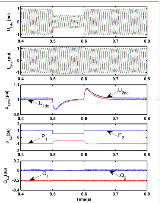
4.6.3 Power reversal ... 77
4.6.4 Harmonics and Total Harmonic Distortion ... 82
4.6.4.1 SPWM Strategy with Phase-Shifted Carrier Strategy ... 82
4.7 Continuity of power supply after fault in VSC module ...84
4.8 Higher Level of Modularity ...85
4.9 Conclusion ...86
CONCLUSION ...89
LIST OF TABLES
Page Table 2.1 Parameters of the VSC-HVDC system ...31 Table 4.1 Main data for the UHVDC system used in the simulation ...73
LIST OF FIGURES
Page
Figure 1.1 A VSC-HVDC system ...9
Figure 1.2 A four-terminal VSC-HVDC system ...11
Figure 1.3 Overall control scheme of the two-terminal VSC-HVDC ...12
Figure 1.4 Basic arrangements of transformers and converters for thyristor-based UHVDC (one pole) ...15
Figure 1.5 Three-parallel phase MMC stations based HVDC (one pole) Adapted from Wang, Hao et Ooi (2013) ...16
Figure 2.1 Configuration of a two-terminal VSC-HVDC system ...21
Figure 2.2 Equivalent circuit of VSC ...21
Figure 2.3 Principle of VSC ...22
Figure 2.4 PI control scheme for VSC in PQ control mode ...25
Figure 2.5 PI control scheme for VSC in VQ control mode ...26
Figure 2.6 HCC scheme for VSC in PQ control mode ...26
Figure 2.7 HCC scheme for VSC in VQ control mode ...26
Figure 2.8 Diagram of hysteresis current controller ...27
Figure 2.9 DCC scheme for VSC in PQ control mode ...28
Figure 2.10 DCC scheme for VSC in VQ control mode ...28
Figure 2.11 Startup and steady state responses for PI decoupling control scheme ...32
Figure 2.12 Startup and steady state responses for HCC scheme ...33
Figure 2.13 Startup and steady state responses for DB control scheme ...34
Figure 2.14 AC voltage sag test for PI decoupling control scheme ...36
Figure 2.15 AC voltage sag test for HCC scheme ...37
XVI
Figure 2.17 Power reversal test for PI decoupling control scheme ...40
Figure 2.18 Power reversal test for HCC scheme ...41
Figure 2.19 Power reversal test for DB control scheme ...42
Figure 3.1 Configuration of the VSC–HVDC system ...47
Figure 3.2 Phasor diagram of between Usand Uc interconnected through a reactor ...48
Figure 3.3 P-Q characteristics of the VSC-HVDC system ...49
Figure 3.4 Outer loop controllers ...51
Figure 3.5 Inner current-loop controllers ...54
Figure 3.6 Startup and steady-state responses ...55
Figure 3.7 Active and reactive power step responses ...57
Figure 3.8 Voltage sag on station 2 AC bus ...58
Figure 3.9 Three-phase to ground fault on station 1 AC bus ...59
Figure 4.1 Proposed VSC-UHVDC transmission (one pole) ...64
Figure 4.2 Overall control system of the VSC-UHVDC transmission system ...67
Figure 4.3 Decoupled Udc-Q control scheme for VSC modules ...68
Figure 4.4 Decoupled P-Q control scheme for VSC modules ...69
Figure 4.5 DC voltage compensation equalizer block for P-Q control side ...70
Figure 4.6 DC voltage compensation equalizer block for Udc-Q control side ...71
Figure 4.7 Phase shifted triangular carriers ...72
Figure 4.8 DC voltages of each VSC at P-Q side without DC voltage compensation equalizer control...74
Figure 4.9 DC voltages of each VSC at P-Q side with DC voltage compensation equalizer control...75
Figure 4.10 (a) Active power and (b) reactive power at P-Q control side ...76
XVII
Figure 4.12 (a) Active power and (b) reactive power at P-Q control side ...78
Figure 4.13 (a) Active power and (b) reactive powernat Udc-Q control side ...79
Figure 4.14 (a) DC voltage and (b) DC current when power reversal happens ...80
Figure 4.15 DC voltages of each VSC module at Udc-Q side ...81
Figure 4.16 AC bus current of four VSC module and harmonic spectrum with the conventional SPWM ...82
Figure 4.17 AC bus current of four VSC modules and harmonic spectrum with the phase shifted carrier SPWM ...83
Figure 4.18 THD of DC bus voltage with the phase shifted carrier SPWM ...84
LIST OF ABREVIATIONS AC Alternate Current
BTB Back To Back
CSC Current Source Converter
DB Dead Beat
DC Direct Current
ETS École de Technologie Supérieure
FFT Fast Fourier Transform
GCT Gate Commutated Turn-Off Thyristor HCC Hysteresis Current Control
HVAC High Voltage Alternating Current HVDC High Voltage Direct Current IGBT Insulated Gate Bipolar Transistor
IGCT Insulated Gate Commutated Turn-Off Thyristor GTO Gate Turn Off Thyristor
KCL Kirchhoff's Current Law KVL Kirchhoff's Voltage Law LCC Line Commutated Converter MMC Modular Multilevel Converter NPC Neutral Point Clamped
PI Proportional Integral PLL Phase Lock Loop PWM Pulse Width Modulation
XX
SPS SimPowerSystem
SPWM Sine-wave Pulse Width Modulation STATCOM Static Compensator
THD Total Harmonics Distortion
UHVDC Ultra-High Voltage Direct Current VSC Voltage Source Converter
LIST OF SYMBOLS AND UNITS OF MEASUREMENTS
A ampere
C reactor capacitance
Cl DC cable capacitance
Cj reactor capacitance of the jth converter
ea,b,c voltages from the AC system referred to VSC side of the transformers
F farad
fc triangle carrier frequency fm modulating frequency
Fc effective/equivalent frequency
H henry
Hz hertz
ia a-phase AC network current ib b-phase AC network current ic c-phase AC network current iaref a-phase reference current ibref b-phase reference current icref c-phase reference current
iaj a-phase current of the jth converter ibj b-phase current of the jth converter icj c-phase current of the jth converter idc DC current
XXII
iq q-axis current
idref d-axis reference current iqref q-axis reference current idc-j DC current of the jth converter iDC DC bus current
idjref reference value of the d-axis current for the jth converter iqjref reference value of the q-axis current for the jth converter
Kp-voltage proportional coefficient of voltage
KI-voltage integral coefficient of voltage
KP-voltagej proportional coefficient of the jth converter voltage
KI-voltagej integral coefficient of the jth converter voltage
KP-power proportional coefficient of active power
KI-power integral coefficient of active power
kg·m2 kilo· square metre
km kilo meter kV kilo volts kW kilo watt
L reactor inductance
Ll DC cable inductance
Lj reactor inductance of the jth converter
M the modulation index
maj a-phase modulating signal mbj b-phase modulating signal
XXIII
mcj c-phase modulating signal
mΩ milli ohm mH milli henry
MVA maga vlots ampere
MW megawatt
N numbers of voltage source converters
P active power
Pref reference active power Pmeas measured active power
pu per unit
Q reactive power
Qref reference reactive power Qmeas measured reactive power R reactor resistance
Rl DC cable resistance
Rj reactor resistance of the jth converter
s second
Sbase base power
sj switching function
t time
T sampling period
usa a-phase AC network voltage usb b-phase AC network voltage
XXIV
usc c-phase AC network voltage uca a-phase VSC-output PWM voltage ucb a-phase VSC-output PWM voltage ucc a-phase VSC-output PWM voltage udc DC bus voltage
udcref DC bus reference voltage ud d-axis voltage
uq q-axis voltage
udcref DC base / reference voltage udc-j DC voltage of the jth converter
Us line-to-line AC bus voltage
Uc converter AC voltage
V volts
Vtot-2 total DC voltage of the AC system 2 Vtot total DC voltage
δ phase angle of the fundamental component of PWM Δepj difference value of the active power for the jth converter
Δedcj difference value of the dc voltage for the jth converter
Δ*e
dcj difference value of the compensation dc voltage for the jth converter
Δidj difference value of the compensation d-axis current for the jth converter
θΔ phase shifting angle of the triangle carrier signals
INTRODUCTION
This chapter describes the research background, problem statements, main objectives, contributions, and the outline of this thesis.
Background
The high voltage direct current (HVDC) transmission technology has been developed due to its recognized significant economic and technical advantages for certain specific power system transmission and interconnection applications such as offshore wind farms, solar plants, different far distant AC systems, and so on (Sood, 2004). Rapid development of modern power electronics technology makes voltage source converter (VSC) based high voltage direct current transmission become an economic way for delivering electric power over long distances (Weimers, 1998). The VSC-HVDC system which employs insulated gate bipolar transistor (IGBT) and Pulse Width Modulation (PWM) switching techniques offers a number of advantages over the conventional line commutated HVDC systems (Ooi et Wang, 1990), such as no need of external voltage source for commutation, fast and independent control of reactive and active power, independent control of reactive power flow at each AC network, feeding weak AC systems or even passive loads, high quality power with less harmonics distortion (Asplund, 2000; Venkataramanan et Johnson, 2003). Therefore, VSC-HVDC transmission system is a competitive way for grid connection over long distance. Modeling, control, and application of VSC-HVDC systems were reported in (Casoria, 2009) , (Chen et al., 2006), (Du, Agneholm et Olsson, 2008), and (Fu et al., 2011) and so on. More articles work on the control of the VSC-HVDC system since a good control system acts like “core chip” which is one of the most important parts for the whole VSC-HVDC system. Nowadays the installations of VSC-HVDC systems at commercial level can be found in Sweden, Australia, the U.S., Mexico, Norway, China and etc.
The demand for power keeps increasing at a scale and speed all over the world in the past latest years. Growing renewable energy sources with power generation becomes increasingly
2
distributed and a growing number of generation facilities located far away from load centers. What’s more, demanding economic objectives and obligations to reduce greenhouse gas have to be met (SIEMENS, 2015). To satisfy these demands, it is necessary to study higher voltage level HVDC power transmission technology-Ultra-High Voltage Direct Current (UHVDC) power transmission technology. In 2010, the first commercial thyristor-based UHVDC transmission system is in operation in China. So far, there are several thyristor converter based UHVDC projects in use by 2015. For example, ±800 kV Xiangjiaba Shanghai UHVDC link is with rated power of 6,400 MW and a transmission distance of 1,935 km (Yang et al., 2011b); ±800 kV Yunnan-Guangdong UHVDC link is with rated power 5,000 MW and a transmission distance of 1,373 km (Rao, 2012); and in India, Champa-Kurukshetra project using 800 kV UHVDC technology transfer rated power 3,000 MW and with a transmission distance of 1365 km (ALSTOM, 2016). More projects are either in planning or under construction in China, India, Brazil, and some other countries. Here, motivated by the success of the thyristor-UHVDC technology and the benefits of VSC-based HVDC technology, VSC modules VSC-based UHVDC transmission system will be firstly studied in Chapter 4.
Problem statements
The statement of the problem A): So far, many literatures about VSC-HVDC control strategies have been developed, such as PI control scheme (Yin, G. Y. Li et T. Y. Niu, 2005; Zheng et Zhou, 2006) in dq coordinates, direct current control strategy by regulating the amplitude and phase of the AC side currents, direct power control method (Rahmati, Abrishamifar et Abiri, 2006) using hysteresis with random switching frequency and a nonlinear control scheme in (Chen, Zheng et Fan, 2006). Most of these controllers are based on dq coordinates and the variables such as the voltages and currents in this controller need use abc/dq and dq/abc coordinates transformation several times, which results in the resutls of control performance more impacted by the performance of phase lock loop (PLL). Usually, it needs to tune four control coefficients for a double close-loop PI control scheme and it is
3
not an easy task. Some other nonlinear control schemes are with complex control algoriths and not easy to design.
Therefore, in order to further exploit the benefits of VSC-HVDC system and improve the dynamic performance of the VSC-HVDC system, it is expeceted to develop some control scheme with easy to design and simple control structure to reach good dynamic performance and good steady-state tracking accuracy behavior.
The statement of the problemB): Most of converter stations for UHVDC operations in the existing projects are thyristor-based converter stations, which usually is a series connection of a two 12-pulse bridges with 400kV rated voltage each to each the rated DC voltage of 800 kV per pole. The innovative solutions of thyristor-based UHVDC have been implemented to fully meet the extended requirements for ultra-high voltage bulk power transmission. However, thyristor-based converters have well-known weaknesses: (a) commutation failures; (2) expensive filters on the AC side and DC side; (3) power flow reversal needs interruption to change voltage polarity mechanically; (4) and no independent active and reactive power control.
In order to address those problems, a solution of two modular multilevel converters (MMC) connected in series per pole was presented for UHVDC application in (Wang, Hao et Ooi, 2013) and each 3-phase MMC based on single-phase H-bridge modules in series. MMC has the advantages over conventional thyristor-based HVDC. However, MMC for UHVDC applications, the weight and size of the power module capacitors of the converters have to be considered since a large quantity of capacitors is needed to form the whole converter stations. At the same time, MMC cell capacitor only conducts single phase AC current, which is one drawback of MMC topology. Besides, the series connection MMC faces the individual DC voltage unequal. Therefore, compared with 12-pulse bridge thyristor-based converter and MMC stations, in this research two-level VSC module based stations are proposed for UHVDC operation.
4
Project objectives
The research mainly focuses on the control of VSC-HVDC transmission system and the application of VSC-HVDC system to UHVDC operation with series-connected VSC modules. The main objectives of the project are described below:
Control of the VSC-HVDC systems): To present good control scheme for the VSC-HVDC system to reach good dynamic response and steady-state tracking accuracy behavior.
Application of the VSC-HVDC systems): Based on the success in thyristor-UHVDC depends on industry having the technical knowledge in insulation so as to connect four 200 kV thyristor-based converter stations in series to bring the DC voltage up to 800 kV or more, in this part, the objectives are: to propose two-level VSC modeules based UHVDC transmission system; then, to develop the corresponding control system for the proposed UHVDC transmission system; lastly, to verify the validation of two-level VSC modules based UHVDC by demanding tests such as active and reactive power step change test and reversal of direction power flow test.
Contributions
The main contributions of this research are as follows:
● Deadbeat current control scheme in abc coordinates with its simple control structure and determined parameters is developed for the VSC-HVDC system, which improves the dynamic responses and the steady-state tracking accuracy behavior of the system; ● Two-level VSC modules based UHVDC transmission system is proposed first time,
and this research reports on the first step which is series connecton VSC modules for UHVDC operation is trouble free;
5
● To improve the stability of the DC voltages, the corresponding control system with DC voltage compensation equalizer is developed for the series-connected VSC modules based UHVDC system. Details test the feasibility of the VSC-UHVDC transmission system for the future “energy high way”.
Two Journal and three conference papers have been submitted for review, they include: Fu, Xiaofan, L.-A. Dessaint, B. T. Ooi. 2016. « Feasibility Study of Series Connection VSCs
for UHVDC Operation ». Submitted to IEEE Trans. Industrial. Electronics, Aug. 2016. (Resubmitted).
Fu, Xiaofan, L.-A. Dessaint, et R. Gagnon. 2016. « Coordinated Control of Offshore Wind Farm Connected to the Grid with DC Series Connection ». Submitted to IEEE Trans. Sustainable Enegy, Aug. 2016. (Submitted)
Fu, Xiaofan, L.-A. Dessaint, R. Gagnon, K. Zhou, et M. Cheng. 2012. « A Comparative Study of Control Schemes for VSC-HVDC Transmission System ». 38th Annual Conference of the IEEE Industrial Electronics Society, IECON 2012, Montreal, Canada, (Oct. 25-28, 2012) p: 2096-2103.
Fu, Xiaofan, L.-A. Dessaint et R. Gagnon. 2011. « Grid-connection of offshore wind farms using VSC-HVDC systems ». in Proc. 10th Int. Workshop Large-Scale Integr. Wind Power into Power Syst. Transm. Netw. Offshore Wind Farms, (Oct. 25-26, 2011) Aarhus, Denmark.
Fu, Xiaofan, L.-A. Dessaint, R. Gagnon, K. Zhou et M. Cheng. 2011. « Modeling and simulation of VSC-HVDC with current deadbeat control ». In Electrical Machines and Systems (ICEMS), 2011 IEEE International Conference on. Beijing, China (20-23 Aug. 2011), p. 1-6.
6
Thesis outline
This thesis is organized as follow:
Chapter 1 Literature review: This chapter mainly reviews on control and application of the VSC-HVDC system. Firstly, the topology and basic principle of VSC-HVDC are introduced, and then different control systems of two-terminal VSC-HVDC are reviewed. The application of VSC-HVDC, especially for UHVDC and offshore wind farms, is also presented and reviewed at the end.
Chapter 2 A comparative studies of control schemes for VSC-HVDC transmission system: this chapter we briefly review the control schemes for the VSC-HVDC system. Then, present conventional PI decoupling control, hysteresis current control and deadbeat current control schemes for the VSC-HVDC transmission system connecting two AC grids. Furthermore, compare their advantages and disadvantages in the VSC-HVDC control systems. Finally, Case of two-terminal VSC-HVDC system is developed in MATLAB/SimPowerSystems and the dynamic performance of the system is evaluated during system start up, grid voltage sags and power reversal changes. Simulation results show that these three control schemes for VSC-HVDC system can offer good dynamic performance when system start up, voltage sags in the grid and power reversal in the system. Different control schemes have different responses performance in the system. Thus, we can choose different control schemes according to the system control requirements and applications.
Chapter 3 Study on VSC-HVDC system with current deadbeat control: In this chapter, a double-loop control scheme is proposed for the VSC-HVDC transmission system connecting two AC grids. A conventional PI controller is used in the outer loop and a current deadbeat controller is presented in the inner loop in order to achieve fast dynamic response, high tracking accuracy and robustness. Cases of two-terminal VSC-HVDC system are developed in MATLAB/SimPowerSystems (SPS) to verify the validity of the proposed control strategy.
7
Simulation results show that the proposed control scheme provides a high performance control solution to the VSC-HVDC system.
Chapter 4 Application of VSC-HVDC: Feasibility study of series connection VSCs for UHVDC operation: Existing Ultra-High Voltage Direct Current (UHVDC) Transmission at 800 kV is based on line-commutated thyristor technology. As HVDC based on Voltage Source Converter (VSC) technology has already reached 350 kV DC voltage, this chapter examines the feasibility of connecting four Voltage Source Converter (VSC) HVDC stations, each rated at 200 kV DC voltage, in series to form a pole UHVDC of 800 kV DC voltage. Feasibility is demonstrated by simulations using the software of MATLAB/SPS.
Conclusion The final chapter concludes with a synopsis of the thesis and identifies topics for further studies.
CHAPTER 1 LITERATURE REVIEW 1.1 Introduction
This Chapter mainly reviews the control and application of the VSC-HVDC system. Firstly, the topology and basic principle of VSC-HVDC are introduced, and then different control schemes for two-terminal and multi-terminal VSC-HVDC are reviewed. The applications of VSC-HVDC transmission, especially for UHVDC and offshore wind farms, are also presented and reviewed in detail at the end.
1.2 Configuration and basic principle of VSC-HVDC
The configuration of a typical two-terminal VSC-HVDC system is shown in Figure 1.1. The configuration of VSC-HVDC system includes Voltage Source Converters (VSC), Converter Reactors (R, L), Transformers (T1, T2), AC Filter and DC Capacitor etc. Each VSC station is
regulated by a corresponding control regulator (Asplund, 2000; Venkataramanan et Johnson, 2003; Weimers, 1998).
Figure 1.1 A VSC-HVDC system
The two sets of converter (station1, station2) shown in Figure 1.1 are VSCs whose bridge arms are based on IGBT. The VSC could be a two-level converter, a three-level converter, or a multi-level converter. Each of its bridge arms is a series of a number of IGBTs and its parallel diodes, so as to enhance the capacity of converters and system voltage under high
10
voltage and high power condition (Sood, 2004). Number of its series is relied on converter’s rated power, voltage level and power electronic devices electric capability and compressive strength. The reactors are used for performance control of active and reactive power during the power transfer process. At the same time, inhibit switching frequency harmonics in converter output current and voltage in order to obtain the expected fundamental current and fundamental voltage. Also, it can inhibit short-circuit current (Sood, 2004). T1 and T2 in Figure 1.1 are transformers which are used to transform AC voltage into secondary voltage adapted to DC link in converter. Transformers can be eliminated when the AC system at low voltage. AC filter is used for the elimination of their output harmonics (Kim, 2009). DC capacitor is converter’s DC-link storage elements, it can buffer the impact of current in bridge arm breaking; reduce DC voltage harmonic (Arrillaga, 2008).
The topologies of two converters of the VSC-HVDC system have been studied in (Andersen et al., 2002; Portillo et al., 2006; Xu et Agelidis, 2007). Different converters are used in the VSC-HVDC system and the two-level bridge is the simplest circuit configuration. Recent practices have extended the principle to multi-level converters by using of capacitors and diodes to increase the number of levels. The voltages can be clamped for different levels such as a three-level neutral point clamped voltage source converter (Noroozian et al., 2003; Yazdani et Iravani, 2006; Zhang et al., 2008) and a three-level flying capacitor voltage source converter (Xu et Agelidis, 2007). The multi-level converters provide improved waveform quality and reduced power losses. Recent years more and more modular multilevel converters (MMC) based HVDC such as (Li et al., 2013), (Wang et al., 2014), (Li et al., 2015), (Beddard, Barnes et Preece, 2015), and (NgTrinh et al., 2016) is developing and blooming. However, due to the increased complexity in converter control with multilevel converters the two-level converter technology is still the most commonly used in practical applications.
In addition, for completeness review, multi-terminal VSC-HVDC is introduced briefly here. As we know, a VSC-HVDC system can achieve a reversal of the power flow by simply reversing the direction of the DC current without changing the polarity of the DC voltage
11
(Chen et al., 2006; Li et al., 2007), this feature is critical for multi-terminal DC system, namely, multi-terminal VSC-HVDC (Chen et al., 2006; Li et al., 2007; Lu et Ooi, 2003). In fact, the multi-terminal HVDC system is a natural extension of two-terminal VSC-HVDC. The converters in a multi-terminal VSC-HVDC system can be either an inverter or a rectifier, depending on its power direction. Figure 1.2 shows a four-terminal VSC-HVDC transmission system. In Figure 1.2, each terminal connects to the AC system which also can be the interfaces of the integrations of offshore wind farms, solar plants, and other renewable energy resources.
Figure 1.2 A four-terminal VSC-HVDC system 1.3 Control of VSC-HVDC
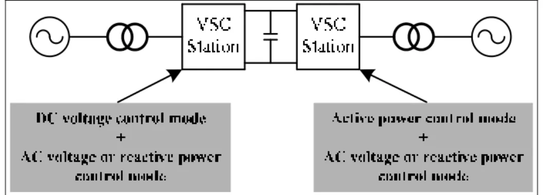
Generally, for a VSC-HVDC system, there are three control modes: a) constant DC voltage control; b) constant DC current or active power; c) constant AC voltage control (Asplund, 2000; Flourentzou, Agelidis et Demetriades, 2009; Sood, 2004). Figure 1.3 shows the overall control scheme of the two-terminal VSC-HVDC system.
12
Figure 1.3 Overall control scheme of the two-terminal VSC-HVDC
In mode a) and b), the reactive power sent to the AC system by the VSC is also controlled. Mode c) is usually used when the VSC-HVDC system feeds power to a passive network. Mode a) and b) are adopted for connecting an active AC network and mode c) is suitable for connecting a passive AC network (Flourentzou, Agelidis et Demetriades, 2009; Mauricio et Exposito, 2006).
Many literatures associated with the modeling and control of VSC-HVDC systems. To exploit the benefits of VSC-HVDC, many control strategies have been developed, such as PI control scheme (Yin, G. Y. Li et T. Y. Niu, 2005; Zheng et Zhou, 2006) in dq coordinates, direct current control strategy by regulating the amplitude and phase of the AC side currents, direct power control method (Rahmati, Abrishamifar et Abiri, 2006) using hysteresis with random switching frequency. Recently various nonlinear controllers have been investigated in (Liang et al., 2005), (Liu et Cai, 2008b), and (Rashed, El-Anwar et Youssef, 2008). In (Lindberg et Lindberg, 1995) and (Ouquelle, Dessaint et Casoria, 2009) an inner current control loop is designed for a digital control implementation and for a dead-beat control of the converter current when the converter is connected to a very strong AC network. An ancillary damping fuzzy control is proposed to change the active power reference dynamically and system stability is improved with the proposed ancillary damping fuzzy control in (Li et al., 2008). In (Du et al., 2007), the control strategy is to regulate the AC and DC voltages on the rectifier side and to control the AC voltage and frequency at the inverter side for improving the quality of power supply to industrial plants. An optimal control
13
strategy based on Newton-Raphson OPF algorithm is proposed in (Pizano-Martinez et al., 2007).
Moreover, there are some further possibilities for the improvement control of VSC-HVDC system. In (Jowder et Ooi, 2004) the static synchronous series compensation (SSSC) is embedded in the HVDC station to improve the dynamic characteristics of the VSC-HVDC link. In (Du, Sannino et Bollen, 2005), it has been investigated what happens when the VSC-HVDC is designed to supply an established AC system by using power flow and AC voltage control. The current limit, as also shown in (Du, Sannino et Bollen, 2005), (Du et al., 2007), and (Du, Agneholm et Olsson, 2008) which are aimed to protect the VSC-HVDC valves, has a significant impact on the dynamics of a VSC-HVDC supplied system. A control system for the VSC-HVDC during island operation and under three-phase balanced fault was investigated in (Du et Bollen, 2006), and it has been found that the current limit of the converters has a significant influence on the dynamic response of the system. Reference (Du, Agneholm et Olsson, 2008) presents three different frequency controllers and their effects on the voltage disturbance ride-through capability of a VSC-HVDC supplied industrial system. As VSCs are modeled as ideal current sources on their DC sides, they are eminently suited for parallel connection across a pair of DC bus. The possible implementation of a multi-terminal HVDC system and various aspects related to the multi-multi-terminal HVDC system have been studied in (Li et al., 2007), (Ding et al., 2009), and (Lu et Ooi, 2002). In (Li et al., 2007) a linear decoupling control is studied and the multi-terminal VSC-HVDC is presented to interconnect wind farms to AC grids. This method highlights the control at the level of wind generator cluster that comprises several permanent magnet synchronous generators without the primary converters on themselves. Multi-terminal VSC-HVDC system is able to connect each doubly-fed induction generator located at different site respectively, and transmit electrical power into main grid (Ding et al., 2009). In (Lu et Ooi, 2002) it describes the optimal acquisition and aggregation of wind power by multi-terminal high voltage direct current based on Sine-wave Pulse Width Modulation (PWM), three-phase VSCs connected at their AC terminals to the wind turbine generators.
14
It should be mentioned that converters in a multi-terminal VSC-HVDC system can be either inverter or rectifier, depending on its power direction. Therefore, in order to maintain power balance in the DC grid, at least one VSC must be assigned to operate as a DC voltage regulator, which automatically functions as a power slack and ensures that the power balance requirement of the DC grid is satisfied (Egea-Alvarez et al., 2013).
1.4 Applications of VSC-HVDC
The VSC-HVDC transmission has a number of technical features that make it especially attractive for many applications such as feeding into passive networks, transmission to/from weak AC systems, enhancement of an AC system, land cable systems, supply of offshore loads, connection to wind farms (on-shore or off-shore) or wave power generation (Sood, 2004; Tang et Ooi, 2007; Xu et al., 2010), etc. Two commercial VSC-HVDC transmission systems projects, Gotland and Tjæreborg, are feeding onshore wind power to the AC system. These projects have shown that VSC-HVDC is capable of handling wind power and reacting rapidly enough to counteract voltage variations in an excellent way.
On the other hand, the fact that neighboring energy sources have already been exploited, so the future power has to be transmitted from very remote locations to consumers. The long transmission distances of large countries like China, India, and Brazil justify the use of Ultra High Voltage DC transmission (UHVDC) at transmission voltages of ±600 kV to ±800 kV (Astrom et al., 2010; Kumar et al., 2009b). So far, all the UHVDC transmission lines are based on thyristor converters. Here, VSC-HVDC based UHVDC will be proposed in this research work. The following sections focus on reviewing the application of VSC-HVDC system for UHVDC operation.
The main feature of UHVDC is the potentiality of long-distance, high-capacity, and low-loss power transmission. Thus, UHVDC offers the promise to meet the aforementioned challenge. Some UHVDC projects are already in operation. For example, the ±800 kV Xiangjiaba-Shanghai UHVDC link, which is the first UHVDC project in the world to go into commercial
15
operation in July 2010, with a rated power of 6,400 MW, transmit power over a distance of 1935 km (Yang et al., 2011a). Yunnan - Guangdong ±800 kV UHVDC link, owned by China Southern Power Grid, rated for 5000 MW to transmit power over a distance of 1418 km (Rao, 2012). Jingping-Sunan ±800 kV HVDC transmission (JPS800) project is rated for 7200 MW to transmit power over a distance of 1935 km, owned by State Grid Corporation of China (Astrom et al., 2010). More UHVDC projects are under construction in India, China and some European countries.
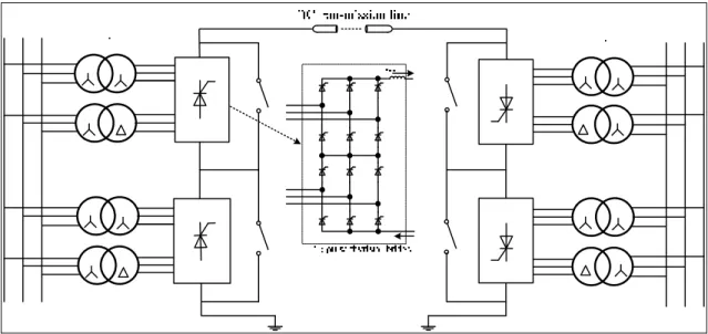
The main advantage of UHVDC is overall transmission loss is low at high transmission voltage of 800 kV. Most of converter stations for UHVDC in the above existing projects are thyristor based converter stations, which usually is a series connection of two 12-pulse bridges with 400 kV rated voltage, and each 12 pulse bridge consists of two 6-pulse bridges of 200 kV each. On their AC sides, one bridge has a wye-delta transformer connection and the other a wye-wye connection to achieve a 30 degree phase shift to eliminate the 6th
harmonic. Thyristor based converter for UHVDC applications, innovative solutions have been implemented to fully meet the extended requirements for ultra high voltage bulk power transmission (Rao, 2012). Figure 1.4 shows the basic arrangements of transformers and converters for thyristor-based UHVDC (one pole).
Figure 1.4 Basic arrangements of transformers and converters for thyristor-based UHVDC (one pole)
16
However, thyristor-based UHVDC has some disadvantages as well, such as facing the risk of commutation failure, needing communication between stations, cannot connect to weak AC system and reactive power and active power cannot control independently. One solution of two modular multilevel converters (MMC) connected in series per pole was presented in (Wang, Hao et Ooi, 2013) for higher voltage HVDC application and each 3-phase MMC based on single-phase H-bridge modules in series. MMC has the advantages over conventional thyristor HVDC in that: (i) there is no commutation failure; (ii) power reversal takes place by reversal of current direction; (iii) costly DC-side and AC-side filters are not required (Wang, Hao et Ooi, 2013). Three-parallel phase MMC stations based HVDC (one pole) is shown in Figure 1.5.
Figure 1.5 Three-parallel phase MMC stations based HVDC (one pole) Adapted from Wang, Hao et Ooi (2013)
However, MMC for UHVDC applications, the weight and size of the power module capacitors of the converters are big trouble since a large quantity of capacitors is needed to form the whole converter stations. At the same time, MMC cell capacitor only conducts single phase AC current, which is intrinsic drawback of MMC topology. Therefore, compared with 12-pulse bridge thyristor converter and MMC stations for UHVDC application, two-level VSC modules based station is a good option.
17
The success in UHVDC depends on industry having the knowledge in insulation and co-ordination in connecting two 400 kV or 500 kV thyristor converter stations in series to bring the DC voltage up to 800 kV or more, for example. In particular, the transformer insulation of the converter station of the higher DC voltage level must be able to withstand the peak AC voltage together with the 400 or 500 kV DC upon which the converter station is connected to. This knowledge on high voltage insulation already exists and in view of the fact that VSC-HVDC stations are reaching high power and high DC voltage ratings. For example, the Caprivi Link is rated at 600 MW at ±350 kV (Magg et al., 2012b) and the EirGrid East-West Interconnector is rated at 500 MW, at ±200 kV (Egan et al., 2013). Hence, the feasibility study of connecting VSC-HVDC stations in series to form VSC-based UHVDC is one of the research contents, which will be presented in Chapter 4.
CHAPTER 2
A COMPARATIVE STUDY OF CONTROL SCHEMES FOR VSC-HVDC TRANSMISSION SYSTEM
2.1 Introduction
Voltage Source Converter (VSC) based High Voltage Direct Current (HVDC) transmission is an electrical transmission technology that has received considerable attention due to the rapid development of modern power electronics technology (Asplund, 2000; Bahrman et Johnson, 2007; Zhang, Harnefors et Nee, 2011). The VSC-HVDC system which employs Insulated Gate Bipolar Transistor (IGBT) and Pulse Width Modulation (PWM) switching techniques, offers a number of advantages over the conventional Line Commutated Converter based HVDC (LCC-HVDC) systems (Mauricio et Exposito, 2006; Venkataramanan et Johnson, 2003; Weimers, 1998), such as no need of external voltage source for commutation, fast and independent control of reactive and active power, independent control of reactive power flow at each AC network, feeding weak AC systems or even passive loads, high quality power with less harmonics distortion, and so on.
To date, many articles related to the modeling, control, and application of VSC-HVDC systems were reported. For example, a dynamic model for a back-to-back HVDC system based on the three-level neutral point diode Clamped (NPC) topology was presented in (Yazdani et Iravani, 2006) and (Zhang et al., 2008). In (Zheng et Zhou, 2006), a small signal dynamic model of VSC-HVDC is established. Reference (Yin, G. Y. Li et T. Y. Niu, 2005) presents an equivalent continuous time state-space model of VSC-HVDC in the synchronous dq reference frame. Moreover, many control strategies for VSC-HVDC systems have been developed in (Yin, G. Y. Li et T. Y. Niu, 2005), (Zheng et Zhou, 2006), and (Casoria, 2009). Most of which are double-loop PI controllers. Also, some various nonlinear controllers (Li et al., 2008; Liu et Cai, 2008a; Rashed, El-Anwar et Youssef, 2008) have been investigated. An inner current control loop was designed for a digital control implementation when the converter is connected to a very strong AC network in (Lindberg et Lindberg, 1995), and
20
(Ouquelle, Dessaint et Casoria, 2009). And an outer PI controller combination of an inner deadbeat current controller is used for power converters in (Fu et al., 2011) to reach good performance for VSC-HVDC system. Recently, power-synchronization control is investigated for VSC-HVDC links connected to weak AC system (Zhang, Harnefors et Nee, 2011). So far, on the practical application side most of the VSC-HVDC projects are still point-to-point DC transmission. Reference (Prieto-Araujo et al., 2011) mentioned some important projects involving HVDC multi-terminal transmission are currently under study. As reviewed above, the control system of the VSC-HVDC is based on an inner current control loop and slower outer controllers. Due to the choice of outer controllers depending on the application (Du, Agneholm et Olsson, 2008), the focus of this chapter is devoted to comparative study on inner control algorithms. The objective of the comparative study is to show the good dynamic behavior of the VSC-HVDC systems.
This Chapter is organized as below: Section 2.2 briefly describes the configuration and modeling of the VSC-HVDC system. Three inner control schemes are presented and compared in section 2.3. In section 2.4, case studies on three control schemes for the VSC-HVDC system under different operating conditions are done to show the good dynamic behavior of the VSC-HVDC systems. Finally, conclusions are drawn in section 2.5.
2.2 Configuration and modeling 2.2.1 VSC-HVDC configuration
The configuration of a typical two-terminal VSC-HVDC system is shown in Figure 2.1. The VSC-HVDC has two identical back-to-back VSC stations, which are linked with a DC bus. Reactors are the ties of power changes between VSC and AC system. The AC filters are placed to absorb high frequency harmonics.
21
Figure 2.1 Configuration of a two-terminal VSC-HVDC system 2.2.2 Dynamic model of VSC
Figure 2.2 Equivalent circuit of VSC
Figure 2.2 shows a general equivalent circuit for the VSC used in the above HVDC transmission system, where usa, usb and usc are balanced three-phase AC network voltages
with usa + usb + usc = 0; uca, ucb and ucc are the VSC’s output PWM voltages; N is the
midpoint DC bus; L is the reactor inductance; R is the reactor resistance; and the VSC could be a two-level converter, a three-level converter, or a multi-level converter. Therefore, the dynamic model of VSC as shown in Figure 2.2 can be described as follows:
(
)
(
)
(
)
0 0 0 0 0 0 a a sa ca b b sb cb c sc cc c i R L i u u L i R L i u u L R L i u u L i • • • − − = − + − − − (2.1)22
The output equation can be written as:
[
]
Ta b c
y= i i i (2.2)
The output PWM voltages of VSC can be expressed as:
( )
1 2cj dc j
u = u s (2.3)
Where, udc is DC bus voltage and sj (j = a, b, c) are switching functions. For a two-level
PWM modulator, the switching functions sj = +1 or sj = -1 (shown in Figure 2.3 a)); for a
three-level PWM modulator, sj = +1, sj = 0 or sj = -1 (shown in Figure 2.3 b)). The amplitude
and phase angle of the three-phase AC currents ia, ib and ic can be controlled by regulating
the fundamental components in VSC’s output PWM voltages. Therefore, the active and reactive power flow can be controlled by regulating the outputs of VSC.
1 T 4 T 1 T 2 T 3 T 4 T Figure 2.3 Principle of VSC
23
2.3 Control scheme for VSC-HVDC system 2.3.1 Overall control description
Generally speaking, the control system of the VSC-HVDC is based on fast inner current loop and slower outer power or DC voltage control, which supply the current references for the inner control loop (Du et al., 2007; Du, Agneholm et Olsson, 2008). For a normal operation of two terminal VSC-HVDC transmission, one VSC station will work in DC voltage and reactive power or AC voltage control mode, where VSC is used to maintain constant DC bus voltage and send required reactive power to its connected AC power network; whereas the other VSC station will operate in active power and reactive power or AC voltage control mode, where VSC is employed to regulate active and reactive power flow as required. The overall control of the two-terminal VSC-HVDC system is already shown in Figure 1.3 in Chapter 1.
According to the three-phase instantaneous power theory, the active power P and reactive power Q on the AC side of VSC, which is in the abc coordinates, can be expressed as:
(
) (
) (
)
3 sa a sb b sc c sa sb c sb sc a sc sa b P u i u i u i Q u u i u u i u u i = + + = − + − + − (2.4)Using coordinates transformation, (2.4) in the synchronous rotating dq coordinates can be rewritten as: sd d sq q sq d sd q P u i u i Q u i u i = + = − (2.5)
Where, usd and usq are the d-axis component and q-axis component of AC network voltage
24
will have usd = Us and usq = 0, where Us is the length of Us. Therefore, (2.5) can be deduced
as:
(
)
(
)
1 1 d sd q sd i u P i u Q = = − (2.6)From (2.6), it can be seen that the active power P and the reactive power Q on AC side of VSC can be independently controlled by regulating id and iq respectively (Flourentzou,
Agelidis et Demetriades, 2009).
In the following sections, we focus on developping the conventional PI decoupling control scheme, hysteresis current control scheme, and deadbeat current control scheme for the VSC-HVDC system.
2.3.2 Conventional PI decoupling control scheme
The PI control scheme, which is adopted for comparison is given in Figure 2.4 and Figure 2.5. Lid and Liq are decoupling compensation components; usd and usq are feed forward
compensation components. As known to all, the transformation matrices are required to transform voltages and currents in the abc coordinate to the synchronously rotating dq
coordinate and later to make the inverse transformation of the current references in the dq
coordinate back to the abc coordinate.
In this control scheme, the voltages and currents need to be transformed several times. One side VSC works in VQ mode for the regulation of DC bus voltage Vdc and reactive power Q,
and the other side VSC will operate in PQ mode for the regulation of active power P and reactive power Q, and vice versa. The PI control scheme achieved decoupled control of active and reactive power.
25
According to (2.6), reference currents (idref, iqref) can be obtained from the corresponding
reference active and reactive power (Pref, Qref). Then, idref and iqref are inputs of the inner PI
current controller. The diagram of PI decoupling control scheme for VSC in PQ control mode is shown in Figure 2.4.
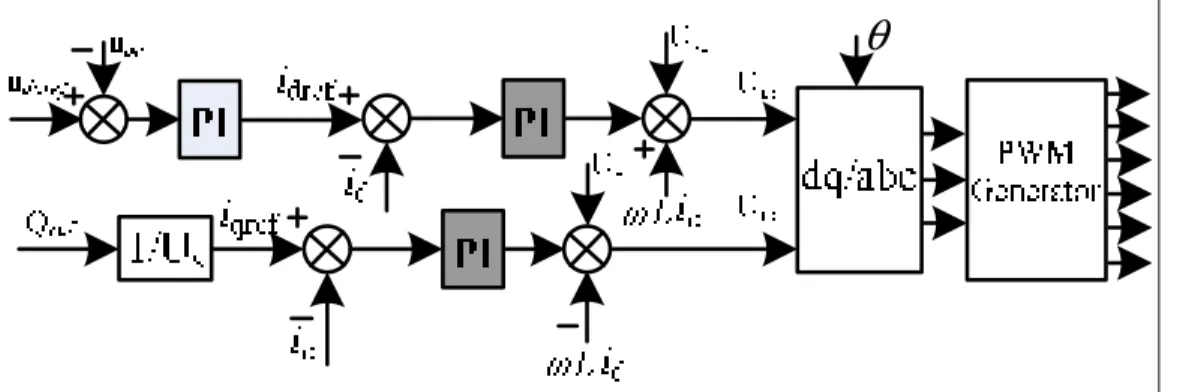
At the same time, the function of VSC in VQ control mode is to maintain constant DC bus voltage and regulate the reactive power Q as required. Figure 2.5 shows the PI control scheme for VSC in VQ control mode. The proposed control scheme is a double-loop PI control structure: a PI controller is used for outer-loop DC voltage regulation, and a PI current controller is used for inner-loop current regulation. The d-axis reference current idref
is the output of outer-loop PI controller as follows:
( ) ( )
dref p dcref dc I dcref dc
i =K u −u +K
u −u dt (2.7)Where, udcref is the DC bus reference voltage. And the Q control mode is the same as VSC in
PQ control mode. The signal θ comes from phase locked loop (PLL) which generates signals synchronized to the AC network voltages.
θ
26
θ
Figure 2.5 PI control scheme for VSC in VQ control mode 2.3.3 Hysteresis current control scheme
The hysteresis current control (HCC) scheme, which is adopted for comparison, is given in Figure 2.6 and Figure 2.7. Where, Figure 2.6 shows the diagram of HCC scheme for VSC in PQ control mode and Figure 2.7 shows the diagram of HCC scheme for VSC in VQ control mode.
θ
Figure 2.6 HCC scheme for VSC in PQ control mode
θ
27
The source of the reference currents (idref, iqref) not only in PQ control mode but also in VQ
control mode is obtained in the same way as described in conventional PI decoupling control scheme section. But here the reference currents (idref, iqref) should be further transformed into
reference currents (iaref, ibref, icref) by using dq/abc transformation in order to provide the
reference current inputs of the inner hysteresis controller.
Figure 2.8 Diagram of hysteresis current controller
The hysteresis current controller is implemented with a closed loop control system and the diagram of hysteresis current controller is shown in Figure 2.8. The error signal, e(t), is the difference between the reference current, ixref, and the measured current, ixactual. When error
reaches an upper limit emax, the transistors are switched to force the current decrease, and
when the error reaches a lower limit the current is forced to increase. Hysteresis band, which is the difference between the maximum value of the error signal and the minimum value of the error signal, directly decides the amount of ripple in output current. Similarly, the signal θ comes from PLL. By using PLL, the effect of signal interference between phases can be reduced.
2.3.4 Deadbeat current control scheme
The deadbeat (DB) current control scheme, which is adopted for comparison is given in Figure 2.9 and Figure 2.10.
28
θ
Figure 2.9 DCC scheme for VSC in PQ control mode
θ
Figure 2.10 DCC scheme for VSC in VQ control mode
In this control scheme, the outer controller of deadbeat current control scheme is exactly the same as for the hysteresis current control scheme, as seen in the Figure 2.9 and Figure 2.10. The inner is a deadbeat current controller and the controller is designed as below.
At the time t = (n + l) T, the corresponding sampled-data equations of (2.1) can be expressed as follows:
(
1)
(( 1 2) 1)* ( )(
( ) ( )*( ( ) 2))
1j j sj j dc
i n+ = b b− b i n + u n −v n u n b (2.8)
where vj(n) is the phase j output control signal at the time t = n T with -1≤vj(n) ≤1 and the
subscript j = a, b, c; udc(n) is DC bus voltage at the time t = nT; b1 = Ln/T; b2 = Rn; Ln and
29
period. Obviously, equation (2.8) can be regarded to be three independent subsystems. From (2.8), the corresponding transfer function of the current loop can be expressed as follows:
( ) ( ) ( ) 1
i j jref
G z =i z i z = z (2.8)
Thus, a deadbeat current controller is obtained:
( )
2(
( ) 1 ( ) ( 1 2) ( ))
( )
j sj jref j dc
v n = u n −b i n + b b i n− u n (2.9)
A more detailed description of the inner deadbeat current control system can be found in (Fu et al., 2011).
2.3.5 Comparison of the three control schemes
In the above paragraphs of this section, we present the PI decoupling control scheme, hysteresis current control scheme, and deadbeat current control scheme respectively.
PI control is one of the most popular control schemes applied for most industrial control systems. The characteristics of PI controller have zero steady state error, maximum overshoot and high settling time. Generally, PI control requires tuning several control coefficients, especially for double close-loop PI control, which is not an easy task.
For comparison, HCC scheme are studied for VSC-HVDC system due to its excellent dynamic performance and low complexity of implementation (Dalessandro et al., 2005). However, it will increase switch loss in the converter with random switching frequency. Furthermore, compared with the above two methods, the third control scheme deadbeat current control scheme as shown in (2.10) is investigated. The advantages of the deadbeat current control scheme for the VSC-HVDC system is that it offers fast dynamic response and high steady-state tracking accuracy with only one sampling time delay. Moreover, the
30
promising advantages of deadbeat current control are simple control structure and algorithms. However, the deadbeat current controller is based on an accurate nominal model of the converter (Zhou et Danwei, 2001). In practice, there may be uncertainties in the converter parameters.
From the three control schemes comparison, we can see that the HCC and deadbeat control scheme take less coordinate transformation steps, and thus less impact by the PLL performance than PI controller does. In view of the different characteristics of these three control schemes, a further comparison study of the three control schemes in the same VSC-HVDC system are presented in the following section.
2.4 Case studies
This section shows the dynamic behavior of the system during startup, AC voltage sags and power reversal. A case of two-terminal IGBT VSC-HVDC system as shown in Figure 2.1 is developed in MATLAB/Simulink, where VSC station 1 will work in VQ control mode and VSC station 2 will operate in PQ control mode. In this case, note that the AC filters are excluded in the simulation system. Different operation cases are studied and described in the following subsections with PI decoupling control scheme, hysteresis current control scheme, and deadbeat current control scheme, respectively. A comparison analysis is made between these three control schemes.
31
Table 2.1 Parameters of the VSC-HVDC system
Parameters Unit Value
AC rated voltage(Us1) kV 100
Reactor resistance (R) Ω 0.075
Reactor inductance (L) H 0.0024
DC base voltage (Udcref) kV 100
DC capacitance (C) F 70e-6
DC-cable resistance (R1) Ω/km 13.9e-3
DC-cable inductance (L1) H/km 0.159e-3
DC-cable capacitance (C1) F/km 2.3e-3
Base power (Sbase) MVA 100
2.4.1 Startup and steady state response test
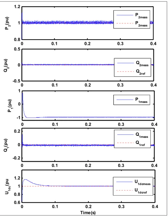
Figure 2.11 to Figure 2.13 show the startup responses with PI decoupling control scheme, HCC scheme, and deadbeat control scheme respectively. From the simulation results, it can be seen that although the DC voltage has a reasonable over voltage at the beginning, all the controlled variables P2, Q2, Q1, and U1dc follow their reference values in good dynamic
performance and in good decoupling control of active and reactive power. In comparison, the waveforms of voltage and power with the deadbeat control scheme are smoother than the others does.
32 0 0.1 0.2 0.3 0.4 0.5 0.7 1 1.2 P 2 (p u) 0 0.1 0.2 0.3 0.4 -0.5 0 0.5 Q 2 (p u) 0 0.1 0.2 0.3 0.4 -1 0 1 P 1 (p u) 0 0.1 0.2 0.3 0.4 -0.2 0 0.2 Q 1 (p u) 0 0.1 0.2 0.3 0.4 0,6 0.8 1 1.2 1,4 Time(s) U 1d c (p u) P2meas P2ref Q2meas Q2ref P1meas Q1meas Q1ref U1dcmeas U1dcref
33 0 0.1 0.2 0.3 0.4 0.6 0.8 1 1.2 1.4 P 2 (p u) 0 0.1 0.2 0.3 0.4 -0.5 0 0.5 Q 2 (p u) 0 0.1 0.2 0.3 0.4 -1 0 1 P 1 (p u) 0 0.1 0.2 0.3 0.4 -0.2 0 0.2 Q 1 (p u) 0 0.1 0.2 0.3 0.4 0.6 0.8 1 1.2 1.4 Time(s) U 1d c (p u) P2meas P2ref Q2meas Q2ref P1meas Q1meas Q1ref U1dcmeas U1dcref