Citation W. Leterme, Dirk Van Hertem
Cable Protection in HVDC Grids Employing
Distributed Sensors and Pro-Active HVDC Breakers IEEE Trans. Power Del., vol PP., issue 99
Archived version “© 2018 IEEE. Personal use of this material is permitted. Permission from IEEE must be obtained for all other uses, in any current or future media, including reprinting/republishing this material for advertising or promotional purposes, creating new collective works, for resale or redistribution to servers or lists, or reuse of any copyrighted component of this work in other works.”
Published version doi:10.1109/TPWRD.2018.2808381
Journal homepage http://ieeexplore.ieee.org/xpl/RecentIssue.jsp?punumber=61
Author contact your email [email protected] your phone number + 32 (0)16 16 32 86 97
Cable Protection in HVDC Grids Employing
Distributed Sensors and Pro-Active HVDC Breakers
Willem Leterme, Member, IEEE and Dirk Van Hertem,Member, IEEE
Abstract—Protection of HVDC grids against short circuits must act in the order of milliseconds to avoid damage to power electronic components and to maintain a stable dc voltage. Therefore, ultra-fast protection algorithms are needed which detect the fault and identify its location. Recently developed communication-less HVDC grid protection algorithms provide a high operation speed but are inherently limited in reach to provide selectivity. In this paper, a new method for protecting HVDC grids with long cables is proposed. The method combines protection algorithms, sensors integrated in the cable joints and pro-active hybrid breakers to achieve an increased performance compared with the state-of-the-art without adding to the overall fault clearing time. This paper describes the proposed method, provides the theoretical basis for the algorithms and presents the results of an in-depth analysis using EMT-type simulations. The simulations were performed in a detailed test system implemented in EMT-type software. Simulation results show that long cables can be protected along their entire length through a combination of the proposed algorithms, although the reach of the individual algorithms is limited.
Index Terms—HVDC circuit breakers, HVDC transmission, power system faults, power system protection, power system transients, protective relaying
I. INTRODUCTION
Protection of HVDC grids must be sufficiently quick since prospective dc fault currents rapidly reach high values which cause damage to the power electronic components of the HVDC converters and breakers. Although recent advances in HVDC breaker technology have enabled fast fault current interruption, current interruption capabilities of existing pro-totypes are still limited [1]–[4]. Consequently, fast protection algorithms are required to quickly detect the fault and identify its location.
Ultra-fast protection of long cable sections using measure-ments at either a single cable end (communication-less algo-rithms), or at both ends (communication-based algoalgo-rithms), is challenging due to attenuation and distortion of traveling waves. Communication-less protection algorithms, as devel-oped in [5]–[9], have an inherently limited reach, whereas communication-based protection algorithms, e.g., described in [5] and [10], are in theory not limited. Nevertheless, due to the wave propagation characteristics, the complexity of these algorithms tends to increase with increasing cable length. Sensors distributed along the cable can be used to limit the length of a protected section and consequently, the W. Leterme and D. Van Hertem are with KU Leuven, Belgium (En-ergyVille/Electa research group, Electrical Engineering Department ESAT, Kasteelpark Arenberg 10 (PB2445), 3001 Heverlee).
Contact: [email protected],
mathematical complexity of the protection algorithms, e.g., the differential protection algorithm proposed in [11].
None of the above mentioned protection algorithms fully exploit the features of pro-active HVDC breakers to improve the security of the protection. Any breaker feasible for HVDC application exhibits a time delay between the initiation of breaker operation and the actual breaker opening, as detailedly discussed in [12]. Pro-active HVDC breakers, e.g., the one introduced in [1], can continue or stop breaker opening af-ter initiating breaker operations. Therefore, for a pro-active HVDC breaker, the time delay between initation of breaker operation and actual breaker opening can be used by protection algorithms to confirm the occurrence of a cable fault after initial detection of a disturbance. As a consequence, the security of the protection can be increased without increasing the total fault clearing time.
In this paper, a new method is developed for protection of cables in HVDC grids with pro-active HVDC breakers. The method aims at protecting long cable sections by making use of sensors distributed along the cable, e.g., integrated in each cable joint or placed at a junction between an underground and submarine cable. Furthermore, the method matches protection algorithms with the pro-active functionality offered by HVDC breakers. As a consequence, the method incurs no cost in terms of operation speed of the overall fault clearing process. The proposed method makes use of traveling wave directional sequence, directional comparison and underreaching derivative protection algorithms. The directional sequence and directional comparison protection are based on the fundamental principles introduced for traveling wave distance and directional com-parison protection of ac overhead line systems in [13]–[15], which are adapted for use in HVDC grids. The underreach-ing derivative protection is based on the communication-less principle introduced for HVDC grid protection in [7], [8].
The paper discusses the operating principles of the method and the protection algorithms, provides formulas to determine their reach and shows how they can be combined with dis-tributed sensors and pro-active HVDC breakers to protect long cables along their entire length. The method is verified with extensive studies using a detailed implementation of a HVDC grid in EMT-type software [16]. The merits of the proposed method are explained based on fundamental theory as well as demonstrated using time domain simulations.
II. OPERATINGPRINCIPLES
A. Two-stage Approach
To interrupt a dc current, pro-active HVDC breakers per-form two consecutive actions, which are in this paper named
taux tmain ∆tbr iline
tf
t
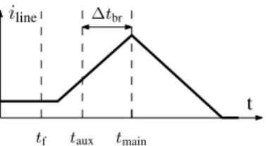
Fig. 1: Line dc current during fault and interruption by HVDC breaker.
“auxiliary breaker action” and “main breaker action”. The auxiliary action creates the necessary conditions for successful main breaker action. The delay between initiation of auxiliary and main breaker action depends on the type of HVDC breaker. The auxiliary action of the breaker reported in [1] consists of opening a mechanical disconnector under zero cur-rent conditions and the associated delay is in the order of two milliseconds. After opening the mechanical disconnector, the main breaker action consists of interrupting the fault current as a pure semiconductor breaker. For the breaker reported in [17], the auxiliary action is due to opening a mechanical breaker under non-zero current conditions. The main breaker action consists of creating a zero-crossing through this breaker with a controllable resonant circuit. The auxiliary delay reported in [17] is in the order of five milliseconds, during which the resonant circuit can be controlled to continue or stop fault current interruption.
HVDC breakers only impact the line currentiline once the main breaker action has started, i.e., aftertmainin Fig. 1. Fig. 1 shows the current through a line in case of a fault and current interruption by a breaker. The instants associated with fault inception, auxiliary breaker action and main breaker action are indicated by tf,taux andtmain, respectively. The delay caused by the auxiliary breaker action is indicated by∆tbr.
The two stages employed in the proposed algorithms are fault detection and fault confirmation, which are used to initiate the auxiliary and main breaker action, respectively. In case the breaker operation delay is minimized, the time available for fault confirmation is limited by the delay caused by the auxiliary breaker action,∆tbr.
In conclusion, the two-stage approach fully exploits the delay caused by the auxiliary action to increase the security of the protection without adding to the overall fault clearing time, as suggested in [1].
B. Detection Functions
The basis for the protection algorithms are the detection functions S1 andS2, defined by:
S1=u′(t)−R
ci′(t), (1)
S2=u′(t) +R
ci′(t), (2)
in whichu′(t)andi′(t)are the superimposed components of the voltage and current measured at the sensor location and Rc is a replica surge impedance to match the characteristic impedance of the protected transmission line.
By comparing these functions against a threshold, the direc-tion of a fault relative to the sensor can be determined. The
use of these detection functions has been well documented in the literature, e.g., in [13], [14].
The detection functions are constructed for each pole in-dependently, i.e., in the phase domain rather than the modal domain. Through avoiding configuration-specific modal trans-formations, this enables direct implementation in any HVDC grid configuration, i.e., asymmetric monopole, symmetric monopole or bipole.
C. Directional Sequence Protection
1) General Principle: The directional sequence protection uses the sequence from the distance technique of [15] to confirm an internal fault. The traveling wave distance protec-tion algorithm introduced in [15] for use in ac overhead line systems first detects a fault through a directional technique before it localizes the fault through a traveling wave distance technique.
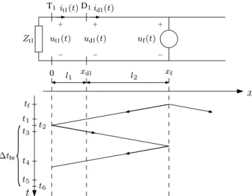
The principle of the algorithm proposed in this paper is shown in Fig. 2. Fig. 2 shows the network to calculate the superimposed components generated by a fault occuring on a cable. The impedanceZt1 is the termination surge impedance at terminal T1. The fault occurs at xf =l1+l2 and voltage and current sensors are located at T1(at x= 0) and at D1 (at xd1=l1). Local intelligence is available at the sensor location to construct the detection functions, compare these against a threshold and transmit the direction of the wave in digital form toT1. Pro-active HVDC breakers are present atT1.
Following events occur sequentially at instants t1-t5: tf Fault inception. Initiation of traveling waves
propa-gating towards both cable ends.
t1 The wave emanating from the fault causes S1,d1 to exceed the detection threshold, which is communi-cated by D1 to T1.
t2 The wave emanating from the fault reaches T1 and causes a sudden voltage drop and increase of the current, which are used to detect the fault and initiate the auxiliary breaker action, i.e.,taux=t2.
t3 The wave reflected at T1causes S2,d1 to exceed the detection threshold, which is communicated by D1 to T1.
t4 The wave reflected at the fault causesS1,d1to exceed the detection threshold, which is communicated by D1 to T1.
t5 Through the sequence of S1,d1, S2,d1 and S1,d1 exceeding the threshold, the directional sequence detection atT1confirms a fault and does not interrupt breaker opening, i.e., tconf=t5.
t6 The breaker initiates the main action and starts the fault current interruption, i.e., t6=tmain.
2) Reach of the protection: The reach of the protection is limited since fault confirmation must occur before the main breaker action is initiated, i.e.,tconf−taux≤∆tbr. From Fig. 2, taux=t2 andtconf=t5are given by
t2=(l1+l2)/vw, (3)
+ − ut1(t) uf(t) it1(t) x t + − T1 tf xf xd1 t1 t6 t5 l1 l2 + − ud1(t) id1(t) D1 0 t2 t3 t4 Zt1
{
∆tbrFig. 2: Principle of traveling wave directional sequence pro-tection algorithm.
where vw and vc are the traveling wave and communication speed, respectively, and∆tprocaccounts for the total time delay in measuring and signal processing at D1 and T1. Sincet5− t2≤∆tbr, l2≤ vw 2 ∆tbr− l1 vc+ l1 vw −∆tproc . (5)
The reach of the proposed directional sequence algorithm thus increases with increasing∆tbr, whereas it decreases with increasingl1and∆tproc.
3) Expected waveforms: The expected waveforms at D1in
Fig. 2 are, for the sake of simplicity of the equations, derived in the time domain with following assumptions: distortionless wave propagation, purely inductive termination and step input at the fault location with amplitudeuf. The detection functions at t1, t3 and t4 forS1 and S2 are, considering a cable with attenuation constant α, anRc perfectly matched to the cable characteristic impedance and a purely inductive terminationL:
S1,t1 = 2e −α(xf−l1)u f, (6) S2,t3 = 2e −α((xf−l1)+2l1)(2e(−t/(L/Zc′))−1)u f, (7) S1,t4 =−2e −α((3(xf−l1)+2l1)(2e(−t/(L/Zc′))−1)u f. (8)
Cable attenuation causes the signal amplitude of all detection functions to decrease with increasingxf and is the lowest for S1,t4. The termination impedance only influences S2,t3 and S1,t4, sinceS1,t1is measured before any reflections occur. The inductive termination results in a reflection factor which varies exponentially between 1 and -1 as a function of time, with a time constant equal to L/Z′
c. Due to the comparatively large effect of the breaker inductor on the termination impedance, as shown in [18], the effect of grid topology changes onS2,t3 andS1,t4 is expected to be relatively low.
D. Directional Comparison Protection
1) General Principle: To protect a cable section between
two sensors distributed along the line, a directional comparison
+ − ut1(t) uf(t) it1(t)
x
t
+ − T1 tf xf xd1 t1 t6 l1 xl2 + − ud1(t) id1(t) D1 0 t3 t4 t5 Zt1 + − ud2(t) id2(t)D2 t2 (1−x)l2{
∆tbrFig. 3: Principle of traveling wave directional comparison protection algorithm (solid lines: traveling waves, dotted lines: communication signal).
protection or permissive overreaching transfer tripping scheme is proposed.
The general principle of the proposed directional protection algorithm is based on the technique introduced in [14]. This technique compares the direction of the fault as indicated by two sensors. If both sensors indicate a fault in the same direc-tion, the directional comparison protection algorithm sends a trip signal to the breaker.
The sequence of fault detection and confirmation is outlined using Fig. 3. Voltage and current sensors are located at T1, D1 and D2 at x = 0,x =xd1 andx =xd2, respectively. At the sensor locations, similar to the directional sequence detection, local intelligence is available to construct the detection func-tions, compare these against a threshold and communicate the direction of the wave digitally to T1.
tf Fault inception. Initiation of traveling waves propa-gating towards both cable ends.
t1 The wave emanating from the fault causes S1,d2 to exceed the detection threshold. The sensors at D2 send a signal to T1to indicate a fault in their forward direction.
t2 The wave emanating from the fault causes S1,d1 to exceed the detection threshold. The sensors at D1 send a signal to T1to indicate a fault in their forward direction.
t3 The fault wave arrives at T1, causing a sudden drop in the voltage and increase of the current. A fault is detected and the breaker auxiliary action is initiated, i.e., t3=taux.
t4 The signal issued by D1 arrives at T1.
t5 The signal issued by D2arrives at T1. Since both D1 and D2 indicate a fault in their forward direction, a cable fault is confirmed and breaker opening is continued.
t6 The breaker initiates the main action and starts fault current interruption, i.e.,t6=tmain.
2) Timing Considerations: For faults within the protected zone of the directional comparison algorithm, the signal issued by D2must arrive before initiation of the main breaker action, i.e., t5−t3<∆tbr. Considering Fig. 3,
t3= l1+xl2 vw , (9) t5= (1−x)l2 vw + l1+l2 vc + ∆tproc. (10) Due to the limited time available for the signal issued by D2to arrive at T1, the protection algorithm has a minimum distance from which the protection zone can start. This distance, (xl2)minis given by:
(xl2)min= vw 2 (l2 1 vw + 1 vc +l1 1 vc − 1 vw + ∆tproc−∆tbr . (11)
The minimum distance of the fault from D1 thus increases with decreasing vc, decreasing ∆tbr, increasing ∆tproc and increasing l2 and l1 (considering vw > vc). The distance provided by (11) can equally be used to estimate (xl2)min of algorithms making use of measurements at the line ends, in which casel1= 0.
For a given l2 and xl2, the maximum distance of the first sensor, (l1)max, to the termination is given by:
(l1)max= ∆tbrvcvw
−l2(vw−vc(2x−1))
vw−vc . (12)
The maximum distance of the first sensor to the termination decreases with (i) decreasing ∆tbr, (ii) increasing l2, (iii) decreasing xl2 and (iv) decreasing vc compared with vw. If vc≥vw, no maximum distance is imposed.
3) Expected waveforms: Under the same assumptions as
Section II-C3, the expected waveform detected at D1 forS1 is given by (6), whereas the one at D2 takes a similar form. Therefore, for sensors distributed along the line, the directional comparison algorithm is termination-independent.
For algorithms using sensors close to a discontinuity, false detections might occur due to the reflection of the wave, e.g., as would be the case for protection of the section between T1 and D1 in Fig. 3. To avoid these false detections in case of a fault in the forward direction of D1, the output ofS2,d1 is suppressed for a period of at least2l1/vw afterS1,d1 exceeds its threshold.
E. Underreaching Derivative Protection
1) General Principle: Since the directional protection has a minimum distance(xl2)min, the section up to(xl2)minmust be protected using a different principle. A communication-less principle based on the derivative as proposed in [5], [7], [8] can be used for this section. This is similar to the direct local tripping feature of the algorithm proposed in [19]. However, since the sensor is not necessarily located at the breaker location, this protection is in this paper indicated by “underreaching derivative protection”.
The operating principle of the underreaching derivative protection is illustrated in Fig. 4. For this case, S1,d1 reaches
+ − ut1(t) uf(t) it1(t)
x
t
+ − T1 tf xf xd1 t1 l1 xl2 + − ud1(t) id1(t) D1 0 t3 Zt1 + − ud2(t) id2(t)D2 t2 (1−x)l2 t4 t 5{
∆tbrFig. 4: Principle of underreaching derivative protection algo-rithm (solid lines: traveling waves, dotted lines: communica-tion signals).
a high value at t = t2, which is communicated to T1 to confirm tripping of the breaker at t = t3. The reach of the underreaching derivative protection algorithm is determined through the threshold which must be exceeded, indicated by Sthr,ur. The breaker eventually issues a main trip at t = t4. Fig. 4 also demonstrates that, in this case, the directional comparison protection associated with the sensors at D1 and D2 cannot issue a confirmation signal to the breaker located at T1before the breaker operation time has elapsed (t5> t4).
2) Expected Waveforms: The expected waveforms for an
internal fault are given by (6), whereas those for an external fault, i.e., beyond the breaker inductor, are given by:
S1ext,t1= 2e
−α(xf−l1)(1−e−t/(L/Zc′))u
f. (13)
As discussed in [7], [8] and demonstrated in (13), waves from external faults are filtered through the low-pass filter formed by the inductor and cable, which distinguishes them from waves resulting from internal faults.
The protection margin as discussed in [20] and hence the security of the underreaching derivative protection is higher compared with single-ended algorithms which cover the entire cable. Since the minimally required reach of the underreaching derivative protection is (xl2)min, the attenuation of the fault wave is e−α((xl2)min−l1). For the communication-less single-ended algorithms, the attenuation of the fault wave is e−αl,
where l is the cable length. Consequently, since ((xl2)min− l1) < l, the attenuation (and, in the non-distortionless case, distortion) of the waveforms to be dealt with by the under-reaching derivative protection is smaller in comparison to those to be dealt with by single-ended algorithms.
III. PRACTICALIMPLEMENTATION
In this section, to discuss the practical implementation aspects, the sensors distributed along the line are indicated by Di, where subscript i indicates the number of the sensor
starting from the terminal T1. The number of sensors along the line is indicated byN.
A. Local sensors
The sensors must provide the superimposed components u′ and i′ to construct the detection functions of (1) and (2) and can, e.g., be integrated into cable joints to provide mea-surements distributed along the line. To integrate current and voltage sensors into a cable joint, possible technologies are a Rogowski coil, e.g., used for partial discharge measurement in [21], and a capacitive voltage sensor as discussed in [22]. Both sensor types provide, in their most basic application, the derivative of the measured quantity, voltage or current. In principle, this is sufficient since only the superimposed components are needed and the dc values can be discarded, but care should be taken to ensure linearity of the sensor gain. In general, all technologies providing an accuracy which is minimally needed for the algorithms can be used.
The local sensors can be placed at joints between two cable sections of a different type, e.g., land and submarine, or of the same type. For existing VSC HVDC point-to-point links, the land cable section can range from the order of one [23] to several tens of kilometers as shown in [24]. The distance between submarine cable joints can be up to 160 km, as reported in [25].
B. Local Intelligence
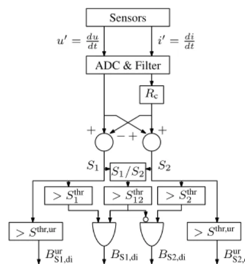
The local intelligence determines the direction of the trav-eling wave and communicates this to the cable terminations (Fig. 5).
First, the detection functions are constructed based on the measurements provided by the sensors. These measurements must be digitized using an analog-to-digital converter (ADC) and, if needed, digitally filtered to extract the superimposed components and improve the SNR. In the scheme shown in Fig. 5, the voltage and current derivative are assumed to be directly available from the sensors. Since for the proposed al-gorithms, the exact values ofS1andS2are of less importance, a constant value forRcis chosen. This allows for a reduction in the local intelligence needed to determine the direction of the traveling wave.
Considering a fault on the protected cable at a distance x in the forward direction of the sensor, the non-ideal detection functions in the forward and backward direction are, in the frequency domain: S1= 1 +Rc Zc e−γxU f (14) S2= 1−Rc Zc e−γxU f, (15)
where γ is the cable propagation constant, Zc is the cable characteristic impedance and Uf is the frequency domain representation of the fault. For a fault in the reverse direction, the expressions for S1 and S2 in (14) and (15) must be interchanged.
The thresholdsS1thrandSthr2 are used to discriminate internal faults from noise. For the underreaching derivative protection, an additional threshold Sthr,ur is used to distinguish between internal and external faults.
Sensors Rc i′=di dt − + + + S1/S2 S1 S2 > Sthr 1 > S thr 12 > S thr 2 BS1,di BS2,di > Sthr,ur Bur S2,di > Sthr,ur Bur S1,di u′=du dt
ADC & Filter
Fig. 5: Filters and logic at sensors distributed along the cable. The ratio of the magnitudes of the detection functions is compared againstS12thr to uniquely determine the direction of the fault relative to the sensor. For a sensor in the line, the ratio S1/S2is higher than one for a fault in the forward direction (cf. (14) and (15)), whereas it is lower than one for a fault in the reverse direction. For a sensor located at the line end, considering an inductive termination, S1/S2 is close to one for a fault in the forward direction and lower than one for a fault in the reverse direction.
The imposed communication burden is restricted to com-municating only four logical bits of information, which results in a lower communication burden compared with differential schemes employing the same sensors. The signals confirming the presence of a forward or backward wave at sensor location Di are indicated by bits BS1,di and BS2,di, which take in this case a value one. The signals confirming a fault within the zone of the underreaching derivative protection are indicated by a value one for bitsBS1,diur or BurS2,di.
C. Algorithm Implementation
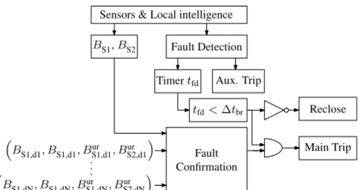
The algorithms based on the operating principles introduced in Section II are implemented at the sensor located at the cable terminations. From the measurements, a fault detection unit starts a timertfd and generates a trip command to initiate the breakers’ auxiliary actions. If any of the protection algorithms indicates a fault within its zone and the timer has not exceeded ∆tbr, a main trip signal is issued. If the timer exceeds∆tbrand none of the algorithms confirm an internal fault, a reclosing signal is issued to the breaker. Alternatively, in case of pro-active HVDC circuit breakers as reported in [1], the reclosing signal can be delayed such that the breaker can immediately interrupt fault currents in backup operation.
The logic for the directional sequence protection algorithm makes use of the first sensors along the cable, i.e., the sensors at D1(Fig. 7a). A trip signal is generated in case the sequence of forward and backward incident waves follows the one shown in Fig. 2. The logic signals associated with the first incident forward and backward wave, BS1,d1 and BS2,d1, are stored for a time ∆t1 and ∆t2, respectively. ∆t1 is at least t5−t′
Sensors & Local intelligence Fault Detection Aux. Trip BS1,d1, BS1,d1, Bur S1,d1, BurS2,d1 tfd<∆tbr Main Trip BS1,BS2 BS1,dN, BS1,dN, Bur S1,dN, BurS2,dN Fault Confirmation Timertfd Reclose
Fig. 6: Logic associated with a breaker located at a cable termination. B S1,d1 ∆t2 ∆t1 B S2,d1 B S1,d1 B’ S1,d1 B’ S2,d1 DS (a) B S1,dk B S1,dm ∆t1 B’ S1,dk DCO (b)
Fig. 7: Logic associated with the directional sequence protec-tion (a) and direcprotec-tional comparison algorithm (b).
of the protection zone andt′
1is the instant at which T1receives a value one forBS1,d1.∆t2 is at leastt5−t′
3, considering the same case as for ∆t1 and wheret′3 is the instant at which T1 receives a value one forBS2,d2.
The logic for the directional protection algorithm making use of sensors at locations Dk and Dm (k<m) is shown in
Fig. 7b. The value one of BS1,dk, must be stored for at least ∆t1=t5−t4, wheret5 is chosen for a fault at(xl2)min.
The underreaching derivative protection for a cable section between two sensors Dk and Dm issues a confirmation signal
when BS1,dkur or BurS2,dk (depending on the direction of the current measurements) takes a value one.
IV. CASESTUDY
A. Test System
The test system used for the case study is the symmetric monopolar system described in [26] with a few changes mentioned hereafter. First, the cable lengths are tripled (Fig. 8) and the cable geometry and material parameters used to model the cables are adapted to those given in Table I. Using these parameters, the traveling wave speed is approximately 182.5 km/ms. Second, voltage and current measurements are added to each cable at 50 km from each bus. Although in this case, each cable is equipped with two distributed voltage and current sensors for demonstration purposes, other combinations of distances or number of sensors along the cable are possi-ble. Third, communication channels are added between each sensor and the communication speed is assumed to be 200 km/ms [27]. The breakers are modeled as pro-active hybrid breakers with an auxiliary delay of 2 ms. An additional delay due to signal processing was not considered.
Bus 1 Bus 2 Bus 3 L14(600 km) L12(300 km) L24(450 km) L34(300 km) L13(600 km) Bus 4
Fig. 8: Test system layout for case study. TABLE I: Cable geometry and material parameters
Layer Thickness [mm] ρ(Ωm) ǫ µ Core 19.5 2.2e-8 Semi-conducting screen 1.5 Insulation layer 1 19.5 2.3 Semi-conducting screen 1.2 Sheath 3 21.4e-8 Insulation layer 2 5 2.3 Armor 5 18e-8 10 Insulation layer 3 4 2.3
The simulations were performed in PSCAD and post-processing of the transient waveforms was done in MATLAB. The PSCAD calculation time-step used for the case study was 1µs. The obtained values were downsampled in MATLAB by a factor of 10 before further processing.
B. Protection Thresholds and Settings
The sensors and their locations onL13are shown in Fig. 9. The sensor locations at the terminals closest to Bus 1 and 3 are indicated by T13 and T31 and those distributed along the line by D13,1 and D13,2, respectively. The measurements, detection functions and bits associated with T13, D13,1 and D13,2 are indicated by subscripts13,d1 andd2, respectively.
1) Timings: For the directional sequence protection, with the case parameters, the ideal reach according to (5) is 134.7 km. The associated values for ∆t1 and ∆t2 are 2 and 1.48 ms (Fig. 7a). Using (11),(xl2)minof the directional protection associated with the breaker at Bus 1 for the cable section between D13,1 and D13,2 is 293.4 km. The associated value for ∆t1 is 2 ms (Fig. 7b). The underreaching derivative protection is used to protect the unprotected cable section between sensors at D13,1 and D13,2. For the breaker with 2 ms opening time, the underreaching derivative protection has to cover a distance of at least 293.4 km from sensor D13,1.
2) Fault Detection: Fault detection in the first stage of the algorithm to initiate the auxiliary breaker action, makes use of the voltage measured at the line ends. A fault is detected if the voltage measured at T13drops below 85% of the nominal voltage of 320 kV.
3) Detection Function Thresholds: Assuming a noise-free
environment, the detection functions as generated by the logic shown in Fig. 5 can be directly used without signal processing. In this paragraph, the selection of the detection function thresholds is illustrated using the forward detection functions associated with T13and D13,1, i.e.,S1,13 andS1,d1, as shown
T13 D13,1 D13,2 T31 LBr LBr Bus 1 Bus 3 50 km 500 km 50 km 125 km 375 km F1 F2
Fig. 9: Sensors located at L13 and location of faults under investigation. 0 100 200 300 400 500 600 100 101 102 103
Fault distance fromT13(km)
S1 S1,13 S1,d1 S ext 1,13 S ext 1,d1
Fig. 10: Detection function values for detection functions associated with T13and D13 as function of fault distance on cableL13and detection function values associated with a fault on Bus 3.
in Fig. 10. Fig. 10 was obtained for faults occuring on L13 with an increasing distance from Bus 1 in increments of 25 km. The selection of the thresholds on forward and backward detection functions associated with the other sensors is done through a similar analysis.
Since the detection functions associated with S1,13 and S1,1,d1 do not need to be used to cover the entire cable length, the thresholds can be adjusted to provide the required reach, the required fault resistance coverage and a sufficient margin to function correctly in a noisy environment. To avoid detection of external faults, i.e., beyond the breaker inductor, the minimum value for the threshold on a detection function is equal to the one obtained for a solid external fault in the direction covered by the detection function. ForS1,13andS1,d1 this corresponds to a solid fault on Bus 3. The maximum value for the threshold on a detection function depends on the required reach for the algorithms and the required fault resistance coverage.
In the case study, the thresholds were chosen such that external faults remain undetected whereas internal faults are detected.S1thrandS2thrwere set to 2, which results in a reach up to the breaker inductor for solid faults. The thresholds Sthr,ur were set to 7.5, which, for solid faults, corresponds to a reach of less than 375 km from D13,1 or D13,2. Furthermore, with this threshold, external solid faults which occur between T31 and LBr are not detected with the underreaching derivative protection (cf. Fig. 10,S1,1,d1takes a value of 2.53 for a fault at T31).
C. Performance
The performance of the proposed protections is illustrated through investigating the response of the detection functions for faults F1 andF2, located at 125 and 375 km from D13,1,
25 26 27 28 29 30 31 32 33 34 35 −80 −60 −40 −20 0 S1 -S2 S1,13 S1,d1 S2,d1 S1,d2 (a) 25 26 27 28 29 30 31 32 33 34 35 0 1 0 1 0 1 0 1 B’S1,d1 B’S2,d1 BS1,d1 DS (b) 25 26 27 28 29 30 31 32 33 34 35 0 1 0 1 0 1 B’S1,d1 B’S1,d2 DCO (c) 25 26 27 28 29 30 31 32 33 34 35 0 1 U D Time (ms) (d)
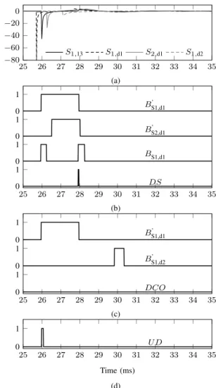
Fig. 11: Detection functions (a) and bits for directional sequence (b), directional comparison (c) and underreaching derivative (d) protection associated with the breakers at T13 forF1.
respectively (Fig. 9). The response for the breaker at Bus 1 is evaluated by showing all detection signals and bits as communicated to that bus. In Fig. 11b, c and d and Fig. 12b, c and d, communication delays are thus included.
1) Directional Sequence Protection: For a solid fault atF1, S1,d1,S1,d1 and S1,d1 exceed the threshold att= 25.70ms, t = 26.26 ms and t = 27.67 ms, respectively. Therefore, BS1,d1’ , B’S2,d1 and BS1,d1 (see Fig. 7a) as communicated to T13 simultaneously take one as output value and the direc-tional sequence protection at T13 confirms an internal fault at t= 27.95ms (Fig. 11). The detection time at the breaker location is 25.98 ms, leaving a difference of 1.97 ms which does not exceed the breaker operation time. Nevertheless, the reach determined with (5) provides an upper limit for the practically realizable reach of the directional sequence protection algorithm in case more extensive signal processing is used for fault detection in a noisy environment.
The directional sequence protection does not respond to a solid fault at F2, as S1,d1 only exceeds the threshold before reflection at the terminal (Fig. 12, where BS1,d1 only takes
25 26 27 28 29 30 31 32 33 34 35 −80 −60 −40 −20 0 S1 -S2 S1,13 S1,d1 S2,d1 S1,d2 (a) 25 26 27 28 29 30 31 32 33 34 35 0 1 0 1 0 1 0 1 BS1,d1’ BS2,d1’ BS1,d1 DS (b) 25 26 27 28 29 30 31 32 33 34 35 0 1 0 1 0 1 BS1,d1’ BS1,d2’ DCO (c) 25 26 27 28 29 30 31 32 33 34 35 0 1 U D Time (ms) (d)
Fig. 12: Detection functions (a) and bits for directional sequence (b), directional comparison (c) and underreaching derivative (d) protection associated with the breakers at T13 forF2.
an output value one once). Consequently, besides the upper limit of the reach predicted by (5), the reach of the directional sequence protection is limited due to the wave propagation characteristics of the cable, which cause attenuation and dis-tortion of the wavefronts.
2) Directional Comparison Protection: The directional pro-tection associated with the cable section between D13,1 and D13,2detects and confirms a solid fault atF2within the time interval of auxiliary breaker actions, whereas it is unable to detect and confirm a solid fault at F1 within the breaker operation time (Fig. 11 and Fig. 12). ForF2, the delay between fault detection and confirmation by the directional comparison associated with D13,1and D13,2is 1.43 ms. ForF1, the delay between fault detection and confirmation is 4.2 ms, which exceeds the breaker operation time.
The underreaching derivative protection associated with the sensors located at D13,1detectsF1without a significant delay since the traveling wave speed and communication time are almost identical. Due to its limited reach, it does not respond to F2.
3) Fault Resistance Coverage: The fault resistance cover-age of the proposed method is assessed through simulating pole-to-ground faults with a varying resistance on cableL13, at locations from 0 to 600 km from Bus 1 with 25 km intervals. The maximum fault resistance, which can be detected with the proposed method using the thresholds of the case study, is shown in Fig. 13 for each fault location. To benchmark the proposed method with a single-ended communication-less principle, the maximum fault resistance which can be detected with the criterionS1,13>2 is also shown.
The proposed method shows an increased fault resistance coverage compared with the benchmark for faults within the interval [300,600] km. Since in this interval both methods use the same thresholds, the increase in fault resistance coverage is due to the lower distance of the fault to the sensor, and thereby, reduced attenuation and distortion of the fault wave perceived at the sensor. The increase in fault resistance coverage is most significant for the interval [500,600] km. In this interval, the maximum distance of the fault to the sensors at D13,2 and T31is only 50 km, whereas for the benchmark the maximum distance of the fault to T13 is 500 to 600 km.
Within the intervals [0,25] and [50,275] km, the method shows a reduced fault resistance coverage compared with the benchmark. Within the latter interval, the decrease in fault resistance coverage is due to the higher threshold setting (Sthr,ur = 7.5) in the proposed method compared with the benchmark (Sthr = 2). In this interval, the fault resistance coverage of the proposed method can be increased above the level of the benchmark by reducing Sthr,ur to Sthr (as shown in Fig. 13 with the markers “Proposed (Case Limit)”). This reduction in threshold setting results in an increase of the underreaching derivative protection zone for faults with low resistance and comes at the expense of a lower margin for discriminating remote internal faults with external ones. In the interval [0,25] km, the decrease in fault resistance coverage is due to the fact that, for the directional comparison principle, the sensor at D13,1 must detect a fault at a distance of at least 25 km. By contrast, for the benchmark method, the maximum distance of the sensor to the fault is 25 km.
The fault resistance coverage of the proposed method can be tuned for each specific application through an appropriate selection of the threshold or an appropriate number of sensors along the cable. In the latter case, the method relies on the lower thresholds associated with the directional comparison algorithm for a longer section of the cable. For instance, with sensors located at equally interspaced intervals of 50 km, a fault resistance coverage of the interval [0,50] and [550,600] km in Fig. 13 could be attained along the entire cable length. For the directional sequence protection associated with D13,1, the maximum fault resistance at a fault location of 125 km from Bus 1 is 5Ω(results are not shown in Fig. 13). There-fore, in case a high fault resistance coverage is required, this algorithm should be complemented with the other algorithms of the proposed method or single-ended communication-less principles.
Finally, given the propagation characteristics on cables [28] and the low coupling between high-frequency phenomena in the poles of a bipolar HVDC system [18], the results
0 50 100 150 200 250 300 350 400 450 500 550 600 100
101 102 103
Fault Distance from Bus 1 (km)
Fault Resistance ( Ω ) Proposed (Case) Proposed (Case Limit) Benchmark
Fig. 13: Maximum pole-to-ground fault resistance for pro-posed method and benchmark as a function of fault location.
10 50 100 150 0 100 200 300 400 500 Sensor distancel1(km) Reach l2 (km) 1 ms 2 ms 3 ms 4 ms 5 ms
Fig. 14: Upper limit for the reachl2of the directional sequence detector as a function of sensor distancel1and breaker opening time.
for pole-to-ground faults are also applicable for monopolar asymmetric or bipolar systems with the same pole-to-ground system voltage. For pole-to-pole faults, the fault resistance will take twice the values of those associated with pole-to-ground faults.
V. DISCUSSION
A. Reach of Protections
1) Directional Sequence Protection: The upper limit of the reach of the directional sequence protection l2, as calculated with (5), increases with increasing breaker opening time and decreasing sensor distance (Fig. 14). For the samel1, the reach increases withvw/2 =91.45 km per extra millisecond breaker opening time. Correspondingly, in case a signal processing delay is considered, the curves shown in Fig. 14 are shifted downwards by ∆tprocvw/2. The upper limit for placing the sensor l1 is given when l2 is zero, e.g., 96 km for a breaker opening time of 1 ms.
As shown in the case study, due to attenuation and distortion of traveling waves, the reach of the directional sequence protection is limited to lower values compared with the ones shown in Fig. 14. To determine the reach in a practical application, further research is required with respect to the impact of noise and the resulting increased need for signal processing.
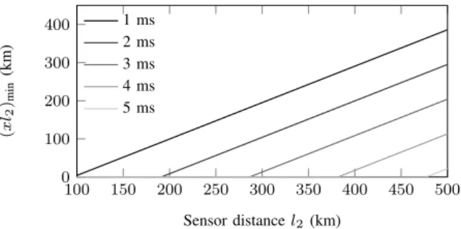
2) Directional Comparison Protection: For the directional comparison protection, above a threshold distance l2,thr,
(xl2)min increases linearly with the distance between the two
100 150 200 250 300 350 400 450 500 0 100 200 300 400 Sensor distancel2 (km) ( x l2 )min (km) 1 ms 2 ms 3 ms 4 ms 5 ms
Fig. 15: Minimum distance (xl2)min of the directional com-parison protection as function of the length of the protected cable section and breaker opening time.
sensors, at the same rate for each of the breaker opening times (Fig. 15). In Fig. 15, due to the low sensitivity of (xl2)min with respect to l1, only the case for l1 = 50 km is shown. When taking into account the signal processing delay, these curves are shifted upwards with ∆tprocvw/2. A decrease in (xl2)min can be achieved in case breaker opening is delayed beyond∆tbr, e.g., as long as the fault current remains below the maximum interrupting capability.
If the distance between the two sensors is lower than a certain value, no minimum reach is imposed, i.e.,(xl2)min= 0. Assumingvw=vc, the threshold distance is given by:
l2,thr = ∆tbrvw
2 . (16)
B. Directional Sequence Protection Settings
The expressions for the expected waveforms, as given in (6)-(8), can be used to select appropriate filters and deter-mine the associated protection thresholds. In particular, these filters and associated thresholds must take into account the exponential tail inS2,t3 as a result of the reflection factor, as shown in (7). For remote faults, this exponential tail interferes with the detection ofS1,t4, especially for long time windows.
In case the distance to the fault is estimated using the directional sequence protection, the imperfect match of Rc withZc together with the thresholds and the exponential tail introduced by the reflection factor can cause misinterpretation for faults close to the sensor. These faults cause a high output of BS1 immediately followed by a high output of BS2. Therefore, the distance estimated by the protection is an overestimation of the actual distance between the sensor and the fault.
Possible solutions to improve the directional sequence pro-tection are (i) to improve the matching between Rc and Zc, as, e.g., done in [10], (ii) to suppress the output of B2 for a certain amount of time after detection ofB1, (iii) to increase thresholds or (iv) to provide additional criteria for detecting forward or backward faults. These options require further investigation towards practical realization.
VI. CONCLUSION
The protection method developed in this paper provides fast and reliable protection of HVDC cables through ex-ploiting the time delay of pro-active HVDC breakers and
making use of sensors integrated in cable joints. The proposed method yields an improved security compared with single-ended communication-less algorithms, although complexity is increased through using communication and an increased number of sensors. Compared with differential schemes em-ploying the same sensors, the proposed method presents a lower communication burden. The proposed method’s fault resistance coverage can be tuned by selecting the appropriate thresholds and number of sensors.
Through combining the concepts available in the literature, which are inherently limited in reach, protection zones which cover long cables along their whole length are set up within the proposed method. The boundaries of the protection zones covered by each of the algorithms can be calculated using the formulas provided in the paper. Furthermore, the descriptions of the expected waveforms under idealized circumstances can be used as guidelines to determine protection settings. Finally, the case study illustrates the correct functioning of the algorithms acting on waveforms obtained with high-fidelity simulations in EMT-type software. To detect faults with a low fault resistance, the proposed method allows for long cable sections between sensors, notwithstanding the low mathemat-ical complexity of its underlying detection functions.
Future work includes investigating improved detection func-tions, characterization of the requirements on measurement equipment, an investigation of noise profiles seen in the measured waveforms and the required signal processing to deal with these.
ACKNOWLEDGMENT
The authors gratefully acknowledge the insightful discus-sions with dr. Tom De Rybel.
REFERENCES
[1] J. Häfner and B. Jacobson, “Proactive Hybrid HVDC Breakers: A key innovation for reliable HVDC grids,” inProc. CIGRÉ Bologna Symp., Bologna, Italy, 13-15 Sep. 2011, 8 pages.
[2] C. Davidson, R. Whitehouse, C. Barker, J. Dupraz, and W. Grieshaber, “A new ultra-fast HVDC circuit breaker for meshed dc networks,” in Proc. IET ACDC, Birmingham, UK, 10-12 Feb. 2015, 7 pages. [3] K. Tahata, S. Ka, S. Tokoyoda, K. Kamei, K. Kikuchi, D. Yoshida,
Y. Kono, R. Yamamoto, and H. Ito, “HVDC circuit breakers for HVDC grid applications,” inProc. AORC-CIGRE 2014, Tokyo, Japan, 27-29 May. 2014, 9 pages.
[4] O. Cwikowski, M. Barnes, R. Shuttleworth, and B. Chang, “Analysis and simulation of the proactive hybrid circuit breaker,” inProc. IEEE PEDS, Sydney, Australia, 9-12 Jun. 2015, pp. 4–11.
[5] J. Descloux, B. Raison, and J.-B. Curis, “Protection algorithm based on differential voltage measurement for MTDC grids,” inProc. IET DPSP 2014, 31 Mar.-3 Apr. 2014, 5.
[6] K. De Kerf, K. Srivastava, M. Reza, D. Bekaert, S. Cole, D. Van Hertem, and R. Belmans, “Wavelet-based protection strategy for dc faults in multi-terminal VSC HVDC systems,” IET Gener. Transm. Distrib., vol. 5, no. 4, pp. 496–503, Apr. 2011.
[7] J. Sneath and A. D. Rajapakse, “Fault detection and interruption in an earthed HVDC grid using ROCOV and hybrid dc breakers,”IEEE Trans. Power Del., vol. 31, no. 3, pp. 973–981, Jun. 2016.
[8] W. Leterme, J. Beerten, and D. Van Hertem, “Nonunit protection of HVDC grids with inductive dc cable termination,”IEEE Trans. Power Del., vol. 31, no. 2, pp. 820–828, April 2016.
[9] R. Li, L. Xu, and L. Yao, “DC fault detection and location in meshed multiterminal HVDC systems based on DC reactor voltage change rate,” IEEE Trans. Power Del., vol. 32, no. 3, pp. 1516–1526, jun 2017. [10] N. Johannesson and S. Norrga, “Longitudinal differential protection
based on the universal line model,” in IEEE Proc. IECON 2015, Yokohama, Japan, 9-12 Nov. 2015, pp. 1091–1096.
[11] D. Tzelepis, A. Dysko, G. Fusiek, J. Nelson, P. Niewczas, D. Vozikis, P. Orr, N. Gordon, and C. Booth, “Single-ended differential protection in mtdc networks using optical sensors,”IEEE Trans. Power Del., vol. PP, no. 99, 2016.
[12] C. Franck, “HVDC circuit breakers: A review identifying future research needs,”IEEE Trans. Power Del., vol. 26, no. 2, pp. 998–1007, Jan. 2011. [13] M. Vitins, “A fundamental concept for high speed relaying,” IEEE Transactions on Power Apparatus and Systems, vol. PAS-100, no. 1, pp. 163–173, Jan 1981.
[14] A. Johns, “New ultra-high-speed directional comparison technique for the protection of e.h.v. transmission lines,”Generation, Transmission and Distribution, IEE Proc. C, vol. 127, no. 4, pp. 228–239, Jul. 1980. [15] P. Crossley and P. McLaren, “Distance protection based on travelling waves,”IEEE Trans. Power App. Syst., vol. PAS-102, no. 9, pp. 2971– 2983, Sep. 1983.
[16] PSCAD, PSCAD User’s manual, Manitoba HVDC Research Centre, 2010. [Online]. Available: https://hvdc.ca/knowledge-library/reference-material
[17] L. Ängquist, S. Norrga, and T. Modéer, “A new dc breaker with reduced need for semiconductors,” inProc. EPE’16 ECCE Europe, Karlsruhe, Germany, 5-9 Sep. 2016, 9 pages.
[18] M. Wang, J. Beerten, and D. Van Hertem, “Frequency domain based dc fault analysis for bipolar HVDC grids,”J. Mod. Power Syst. Clean Energy, vol. 5, no. 4, pp. 548–559, Jul 2017.
[19] M. Chamia and S. Liberman, “Ultra high speed relay for EHV/UHV transmission lines – development, design and application,”IEEE Trans. Power App. Syst., vol. PAS-97, no. 6, pp. 2104–2116, Nov. 1978. [20] N. Johannesson, S. Norrga, and C. Wikström, “Selective wave-front
based protection algorithm for MTDC systems,” inProc. IET DPSP 2016, Edinburgh, UK, 2016.
[21] T. Eriksson and K. Johansson, “Device for sensing partial discharges in test objects, preferably a cable joint,” U.S. Patent 6 297 645 B1, 2001. [22] T. De Rybel and E. Vandewinckel, “High voltage measurement systems,”
U.S. Patent 9 759 755 B2, 2017.
[23] J. Dorn, H. Gambach, J. Strauss, T. Westerweller, and J. Alligan, “Trans Bay Cable - a breakthrough of VSC multilevel converters in HVDC transmission,” inProc. CIGRÉ San Francisco Colloquium, San Francisco, CA, 7 Mar. 2012, 7 pages.
[24] F. Wang, L. Bertling, T. Le, A. Mannikoff, and A. Bergman, “An overview introduction of VSC-HVDC: State-of-art and potential ap-plicaions in electric power systems,” inProc. CIGRÉ Bologna Symp., Bologna, Italy, 2011, 10 pages.
[25] T. Worczyk, Submarine Power Cables. Berlin, Germany: Springer Verlag, 2009.
[26] W. Leterme, N. Ahmed, L. Ängquist, J. Beerten, D. Van Hertem, and S. Norrga, “A new HVDC grid test system for HVDC grid dynamics and protection studies in EMTP,” inProc. IET ACDC, Birmingham, UK, 10-12 Feb. 2015, 7 pages.
[27] J. Descloux, “Protection contre les courts-circuits des réseaux à courant continu de forte puissance,” Ph.D. dissertation, Université Grenoble Alpes, Grenoble, France, Sep. 2013.
[28] A. Ametani, “Wave propagation characteristics of cables,”IEEE Trans. Power App. Syst., vol. PAS-99, no. 2, pp. 499–505, March 1980.
Willem Leterme (S’12,M’16) received the M.Sc. and Ph.D. degree in electrical energy engineering from KU Leuven, Belgium, in 2012 and 2016. Currently, he is a postdoctoral researcher at KU Leuven/EnergyVille, Belgium. His research interests are in the area of power system protection, in which he focuses on protection of multi-terminal and meshed VSC HVDC systems.
Dirk Van Hertem(S’02,SM’09) received the Ph.D. degree from KU Leuven,
Belgium, in 2009. In 2010, he was a member of EPS group at the Royal Institute of Technology, Stockholm, Sweden. Since 2011 he is Assistant Professor at KU Leuven, Belgium. His fields of interest are power system operation and control in systems with FACTS and HVDC and the transmission system of the future, including offshore grids and the supergrid. He is an active member of IEEE PES and IAS and CIGRÉ.