Interleaved Convolutional Code and Its Viterbi
Decoder Architecture
Jun Jin Kong
Department of Electrical and Computer Engineering, University of Minnesota, 200 Union Street, Minneapolis, MN 55455, USA Email:[email protected]
Keshab K. Parhi
Department of Electrical and Computer Engineering, University of Minnesota, 200 Union Street, Minneapolis, MN 55455, USA Email:[email protected]
Received 4 February 2003 and in revised form 17 June 2003
We propose an area-efficient high-speed interleaved Viterbi decoder architecture, which is based on the state-parallel architecture with register exchange path memory structure, for interleaved convolutional code. The state-parallel architecture uses as many add-compare-select (ACS) units as the number of trellis states. By replacing each delay (or storage) element in state metrics memory (or path metrics memory) and path memory (or survival memory) withIdelays, interleaved Viterbi decoder is obtained whereIis the interleaving degree. The decoding speed of this decoder architecture is as fast as the operating clock speed. The latency of proposed interleaved Viterbi decoder is “decoding depth (DD)×interleaving degree (I) + extra delays (A),” which increases linearly with the interleaving degreeI.
Keywords and phrases:interleaved convolutional code, interleaved Viterbi decoder, burst-error correction, random-error correc-tion, interleaving.
1. INTRODUCTION
It is well known that burst-error is a serious problem es-pecially in storage and wireless mobile communication sys-tems. In order to cope with burst-error, interleaving, denoted here as channel interleaving, with random-error correcting code, is generally used. Interleaving randomizes error bursts by spreading the erroneous bits with introducing a very long delay time, which is intolerable in some applications.
A burst-error correcting Viterbi algorithm, which com-bines maximum likelihood decoding algorithm with a burst detection scheme, instead of using channel interleaving, was proposed in [1] and extended to the Q2PSK in [2]. This adap-tive Viterbi algorithm (AVA) outperforms interleaving strate-gies in the presence of very long bursts. However, when many short error bursts are present, AVA is inferior to interleav-ing scheme. An interleaved convolutional code also can be used for burst-error correction [3]. A modified Viterbi al-gorithm (MVA) [4], which is based on the multitrellis de-composition [5], was presented for interleaved convolutional code. The MVA introduces a much smaller delay time and much lower memory requirements than channel interleav-ing techniques with convolutional code. However, the im-plementation of MVA in [4], which uses as many delay el-ements as decoding depth (DD)×interleaving degree (I) for
each code word component, is not area efficient. Some appli-cations of interleaved convolutional code for asynchronous transfer mode (ATM) networks [6] and image communica-tion systems [7,8,9] have been proposed.
In this paper, an area-efficient high-speed interleaved Viterbi decoder architecture, which has state-parallel archi-tecture with register exchange path memory structure, is pro-posed. This paper is an expanded version of [10]. A brief introduction of the interleaved convolutional code is given inSection 2. A proposed interleaved Viterbi decoding algo-rithm and its architecture for interleaved convolutional code are shown inSection 3.
Interleaved convolutional
code encoder A
MUX
(a)
DE-MUX
A Interleaved Viterbi decoder
(b) Figure1: Interleaved convolutional code block diagram: (a) encoder (b) decoder.
xi DI
xi−I
DI xi−2I
C1 i
C2 i
(a)
xi
ai D
I
ai−I D I
ai−2I
C1 i
C2 i
(b)
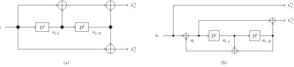
Figure2: Interleaved convolutional code encoder with interleaving degreeIform=2,R=k/n=1/2, and (a)G=(7,5)8NRNSC code and (b)G=(1,5/7)8RSC code.
An interleaved convolutional code can be obtained from a nonrecursive nonsystematic convolutional (NRNSC) code or a recursive systematic convolutional (RSC) code as shown inFigure 2. In order to illustrate the algorithm, we will con-sider an (n, k, m)=(2,1,2) binary convolutional code with the following generator polynomials (G):
(1) NRNSC:
G(D)=g1(D), g2(D)=(7,5)
8=
1 +D+D2,1 +D2, (1a) (2) RSC:
G(D)=g1(D), g2(D)=(1,5/7) 8
=1,1 +D2/1 +D+D2.
(1b)
For these codes, the generator polynomials of interleaved convolutional code with interleaving degreeIbecome
(1) interleaved NRNSC:
GDI=g1DI, g2DI=1 +DI+D2I,1 +D2I, (2a)
(2) interleaved RSC:
GDI=g1DI, g2DI=1,1 +D2I/1 +DI+D2I (2b)
which yield (2,1,2I) interleaved convolutional code. From equations (1) and (2), we can see that each delay element (D) in generator polynomials is replaced byIdelays as shown in
Figure 2.
The encoding and decoding processes will be explained inz-transform domain. In this representation, each delay el-ementDof generator polynomials is replaced byz−1.
A binary information sequence to be encoded is repre-sented as
X(z)= ∞
k=0
akz−k, ak∈ {0,1}, (3)
whereakis a coefficient of information sequence and it has the values 0 or 1 since the binary system is considered. For an (n,1, mI) interleaved convolutional code, the generator poly-nomials with interleaving degreeIare
GizI=m j=0
gi
jz−jI, (4)
where gij is a coefficient of the generator polynomials and
gi
j ∈ {0,1},g0i =gmi =1, andi =1,2, . . . , n. For this inter-leaved convolutional code encoder, codeword (encoder out-put) sequences are generated as follows:
CizI=GizIX(z)=m j=0
gi jz−jI·
∞
k=0
akz−k. (5)
Generator polynomials, for the case of n = 2,m =2, and
I = 2, and withg(D) = (7,5)8 for original convolutional code, are
G1z2=1 +z−2+z−4,
G2z2=1 +z−4. (6)
Codeword (encoder output) sequences of this encoder are
C1z2=G1z2X(z)=C1 0
z2+C1
1
z2, C2z2=G2z2X(z)=C2
0
z2+C2
1
where
Two independent codeword sequences are obtained by inter-leaving with degree 2: (C10(z2), C20(z2)) and (C11(z2), C21(z2)). They are transmitted alternatively. Extra delays are used for one codeword sequence to add more interleaving effect. In this case, the decoder also requires extra delays to adjust tim-ing of received sequences as shown inFigure 1.
3. INTERLEAVED VITERBI DECODING
Viterbi decoding algorithm consists of branch metrics calcu-lation, add-compare-select (ACS) operation, and estimation of the information sequence from the survival path informa-tion. Hamming distance (hard decision) or Euclidean dis-tance (soft decision) between the received data and the pos-sible codeword sequences are computed in the branch met-rics calculation unit. Those branch metmet-rics are accumulated and the most likely path (survival path) is selected by the ACS unit. For a binary convolutional code with the code rate (R) isk/n, the number of possible codeword is 2n. From the survival path information, the decoded data sequence is ob-tained.
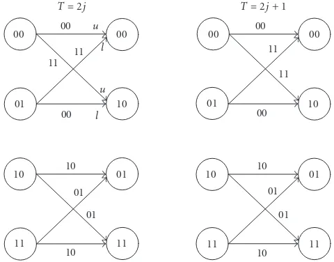
Interleaved Viterbi decoding algorithm is based on the decomposed trellis diagram. The trellis diagram of an (n, k, mI) interleaved convolutional code can be decomposed toI×(n, k, m) trellis diagrams.Figure 3shows the decom-posed trellis diagram of (2,1,2×2) NRNSC. As we can see in
Figure 3, each decomposed (n, k, m) trellis diagram is identi-cal.
A received sequence, which may be corrupted by errors, can be represented as
Ri(z)=∞ k=0
ri
kz−k, i=1,2, . . . , n. (9)
From these sequences, branch metrics can be calculated as
Λp(z)=bmr1
Figure3: Decomposed trellis diagram for (2,1,2×2) interleaved convolutional code inFigure 2a.
represent the branch metrics and the possible codeword, re-spectively. Using this branch metrics, ACS operations can be executed as
z−(k+1)I−jγs(z)=Z−kI−jminλu
k+γu, λlk+γl, (11)
whereλsk andγsrepresent branch metrics and state metrics (or path metrics or accumulated state metrics), respectively;
sstands for trellis state, which varies from 0 to 2m−1;k = 0,1,2, . . . ,∞; and j = 0,1,2, . . . , I −1. The superscriptsu andlin (11) mean, respectively, upper and lower branches that merged into a trellis state (see Figure 3). The survivor path information (referred to as path select signal, PS) of this ACS operation is as follows:
PSs(z)= when the lower branch is selected for a trellis state s. From (11), (12), andFigure 3, we know thatI delays (or storage elements) are needed to guarantee proper ACS operations.
R0
Figure4: A proposed Viterbi decoder architecture for an (n,1, mI) interleaved convolutional code.
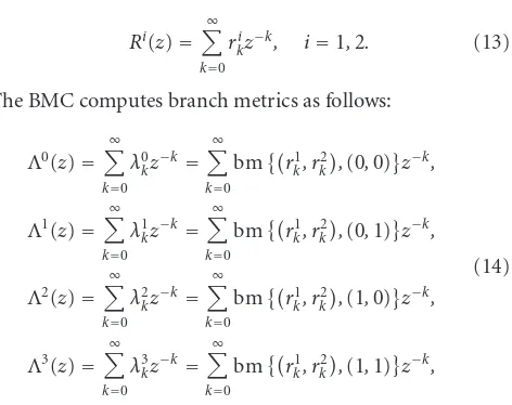
In case ofn=2,m=2, andI=2, received information sequences are represented as
Ri(z)=∞ k=0
ri
kz−k, i=1,2. (13)
The BMC computes branch metrics as follows:
Λ0(z)= rics between the received symbols and the possible code-words (0,0), (0,1), (1,0), and (1,1), respectively. These branch metrics are used in ACS computation. The ACS unit adds branch metrics (λ) and previous state metrics (γ), and then selects minimum state metrics from two incoming branches (seeFigure 3) as follows:
z−2(k+1)−jγs(z)=z−2k−jminλu
The selected state metrics are stored in the SMM as a new state metrics. Form = 2, which means that the number of trellis states are 2m=22=4, we need four PS signals: PS0(z), PS1(z), PS2(z), and PS3(z). These PS signals go into the PM.
Since the number of trellis states of interleaved convolu-tional code, which is 2mI for the (n, k, mI) interleaved con-volutional code with interleaving degree isI, for large inter-leaving degree or encoder constraint length (K =m+ 1) is very large, a straightforward state-parallel implementation of the Viterbi algorithm for this code requires huge hard-ware resources. For (2,1,2 ×4) interleaved convolutional code, the number of trellis states is 256, which is the same as for K = 9. Therefore, area-efficient high-speed Viterbi decoder architecture for interleaved convolutional code is needed.
By substitutingI delays for each delay (or storage) ele-ment in SMM and path memory cell (PMC) of PM, an area-efficient high-speed interleaved Viterbi decoder architecture for interleaved convolutional code is obtained. In this archi-tecture, we can get the throughput rate of the Viterbi decoder as high as the operating clock speed. Since the decoding la-tency of the state-parallel Viterbi decoder with register ex-change path memory structure is the same as the decoding depth, the decoding latency of the interleaved Viterbi de-coder is increased by I×DD. Therefore, the decoding la-tency of proposed architecture is the decoding depth mul-tiplied by the interleaving degree, that is, decoding latency = DD×I. Since interleaved convolutional coding scheme uses extra delay (A), its overall decoding latency becomes DD×I+A.
A proposed state-parallel Viterbi decoder architecture for interleaved (n,1, mI) convolutional code is shown in
w FIFO 0 (I×w)
w
w FIFO 1
(I×w)
w
. . .
. . .
. . .
w FIFO 2m−1
(I×w)
w
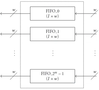
Figure5: Interleaved SMM architecture using FIFO.
If the decoding speed is not critical, state-serial archi-tecture, which uses less ACS units than the number of trel-lis states without changing SMM and PM structures, can be used. But it needs a control unit for proper connection between ACS units and SMM and PM. The BMC and the ACS unit architectures of the proposed Viterbi decoder are identical with that of the original Viterbi decoder architec-ture.
In general, random access memory (RAM) andD-type flip-flop are used as an SMM for the serial and state-parallel noninterleaved Viterbi decoders, respectively. For both cases, its size becomes interleaving degree (I)×number of trellis states (2m)×state metrics width (w).Figure 5shows an alternative SMM architecture, which uses first-in first-out (FIFO) memory.
Interleaved PM and interleaved PMC (IPMC) architec-tures for proposed interleaved Viterbi decoder are shown in
Figure 6.
The basic architecture of this interleaved PM is exactly the same as the architecture of the original register exchange PM architecture. However, it uses modified PM cell archi-tecture that consists of one multiplexer and I storage ele-ments as shown in Figure 6b.D-type flip-flop is generally used for storage element in register exchange PM structure. Due to the extra delay elements in IPMC, the estimated in-formation sequence can be properly recovered from the PM. Also by virtue of its simple structure, placement and routing of path memory cells are easier than that of a straightfor-ward implementation. Reduction of power consumption is also expected in this proposed Viterbi decoder architecture. The PS0, PS1, PS2, and PS3are used as select signals for the first, second, third, and fourth row of IPMC in PM, respec-tively. The connection of IPMC in PM is exactly the same as the trellis diagram. The path select signals can be used as inputs of the IPMC for the first column in PM. When the DD is large enough, that is, DD ≥ 4K, the outputs of the IPMC at the last column in PM have the same values with very high probability. Therefore, some IPMC in PM can be
removed with ignorable performance degradation as shown inFigure 6a.
The Viterbi decoder for interleaved convolutional code also can be implemented in I-parallel manner. It consists of I-parallel Viterbi decoder components. Each Viterbi de-coder component is used for decoding each interleaved data sequence.
InTable 1, the complexity, latency, and throughput rate of this proposed Viterbi decoder architecture are compared with a straightforward implementation.
FromTable 1, we can see that the hardware complexity of the proposed Viterbi decoder architecture is much smaller than that of the straightforward implementation for the same throughput rate. For I = 2 and m = 2, we can achieve hardware reduction of 75% for ACS, 50% for SMM, and 50% for PM, approximately. Furthermore, the connections of proposed architecture are reduced. The proposed inter-leaved Viterbi decoder architecture saves areas for the ACS units and PM. Since the IPMC uses less number of multi-plexers, the size of IPMC is smaller than that of (I×PMC) as shown inFigure 6b.
However, the latency of this proposed architecture, which is linearly increased with the interleaving degree, is the largest among three different implementations.
4. CONCLUSION
An area-efficient high-speed Viterbi decoder architecture is proposed to decode (n,1, mI) interleaved convolutional code. By replacing each delay (or storage) element in state metrics memory and path memory withIdelays, interleaved Viterbi decoder is obtained. More hardware complexity re-duction can be achieved with higher interleaving degree. It means that this proposed architecture is more area efficient for interleaved Viterbi decoder with higher interleaving de-gree.
However, it is inevitable that the latency of this pro-posed architecture is increased as the interleaving degree is increased. The latency of proposed interleaved Viterbi de-coder itself is “decoding depth (DD)×interleaving degree (I),” which is linearly increased with the interleaving degree. Since interleaved convolutional coding scheme uses extra de-lay (A), its actual decoding latency becomes DD×I+A.
The performance of this interleaved convolutional cod-ing scheme depends on the interleavcod-ing degree and the size of extra delay.
ACKNOWLEDGMENTS
IPMC 0,0
IPMC 0,1
IPMC
0,2 · · ·
IPMC 0,9
IPMC 0,10
IPMC 0,11
Decoded data PS0
IPMC 1,0
IPMC 1,1
IPMC
1,2 · · ·
IPMC 1,9
IPMC 1,10 PS1
IPMC 2,0
IPMC 2,1
IPMC
2,2 · · ·
IPMC 2,9 PS2
IPMC 3,0
IPMC 3,1
IPMC
3,2 · · ·
IPMC 3,9 PS3
CLK
(a)
Interleaved path memory cell Ai
Bi
PSi
CLK · · ·
· · · RB
A Y B
S
Delay 1
D Q
CLK RB
Delay 2
D Q
CLK RB
· · ·
DelayI
D Q
CLK RB
Qi−I
(b)
Figure6: (a) Interleaved PM for DD is 12 (b) IPMC architectures for (n, k,2I).
Table1: Complexity, latency, and throughput rate of interleaved Viterbi decoder for an (n,1, mI) interleaved convolutional code.
Parameters Proposed Straightforward I-parallel
No. of trellis states 2m 2mI I×2m
No. of ACS 2m 2mI I×2m
Size of SMM I×(bit widths of SMM×2m) Bit widths of SMM×2mI I×(bit widths of SMM×2m)
Size of PM DD×2
m×IPMC
DD×2mI×PMC I×DD×2m×PMC
≈DD×2m×I×PMC
Latency DD×I+A DD DD
Throughput rate Same as ACS clock speed
REFERENCES
[1] C. B. Schlegel and M. A. Herro, “A burst-error-correcting Viterbi algorithm,”IEEE Trans. Communications, vol. 38, no. 3, pp. 285–291, 1990.
[2] D. J. van Wyk and L. P. Linde, “Application of a burst-error-correction Viterbi algorithm to Q2PSK on Rician fad-ing channels,” inProc. IEEE 4th Africon Conference in Africa (AFRICON ’96), vol. 2, pp. 576–581, Stellenbosch, South Africa, September 1996.
[3] S. Lin and D. J. Costello Jr, Error Control Coding: Funda-mentals and Applications, Prentice-Hall, Englewood Cliffs, NJ, USA, 1983.
[4] N. Benvenuto, L. Bettella, and R. Marchesani, “Performance of the Viterbi algorithm for interleaved convolutional codes,”
IEEE Trans. Vehicular Technology, vol. 47, no. 3, pp. 919–923, 1998.
[5] N. Benvenuto and R. Marchesani, “The Viterbi algorithm for sparse channels,”IEEE Trans. Communications, vol. 44, no. 3, pp. 287–289, 1996.
[6] K. Y. Wong and K. Takahashi, “Cell loss recovery using inter-leaved convolutional code for ATM networks,”IEE Electronic Letters, vol. 36, no. 13, pp. 1126–1127, 2000.
[7] D.-F. Yuan, Z.-W. Li, A.-F. Sui, and J.-J. Luo, “Performance of interleaved (2,1,7) convolutional codes in mobile image com-munication system,” inProc. IEEE Wireless Communications and Networking Conference (WCNC ’00), vol. 2, pp. 634–637, Chicago, Ill, USA, September 2000.
image transmission system over mobile fast-fading channels,” inProc. IEEE Wireless Communications and Networking Con-ference (WCNC ’00), vol. 3, pp. 1492–1495, Chicago, Ill, USA, September 2000.
[9] L.-F. Peng, D.-F. Yuan, Z.-W. Li, and D.-F. Guo, “Performance of the combination of interleaving and wavelet noise cancella-tion in mobile image transmission system,” inIEEE Proc. 11th IEEE International Symposium on Personal, Indoor, and Mo-bile Radio Communication (PIMRC ’00), vol. 1, pp. 237–240, London, UK, September 2000.
[10] J. J. Kong and K. K. Parhi, “Viterbi decoder architecture for interleaved convolutional code,” inProc. Conference Record of the 36th Asilomar Conference on Signal, Systems, and Comput-ers (Asilomar ’02), vol. 2, pp. 1934–1937, Pacific Grove, Calif, USA, November 2002.
Jun Jin Kongreceived the B.S. and M.S. de-grees from the Department of Electronics Engineering in Hanyang University, Korea, in 1986 and 1988, respectively. Since 1989, he has worked in Samsung Advanced Insti-tute of Technology and Central R&D Cen-ter in Samsung Electronics Co., Ltd., Korea. He has developed application-specific inte-grated circuits (ASIC) for communication systems and storage systems. He is an
inven-tor of several patents on error correcting code decoders. His re-search in error correcting codes addresses effective decoding algo-rithms and VLSI architectures. He served as a steering committee member of the Coding and Information Society in Korean Institute of Communication Sciences. He is currently pursuing for Ph.D. de-gree at the Department of Electrical and Computer Engineering in the University of Minnesota, Minneapolis, USA as the recipient of the Samsung Electronics Corporation, Ltd. scholarship. His cur-rent research interests include quantum error-correcting codes and their decoder architectures.
Keshab K. Parhiis a Distinguished McK-night University Professor in the Depart-ment of Electrical and Computer Engineer-ing at the University of Minnesota, Min-neapolis. He was a Visiting Professor at Delft University and at Lund University, a Visiting Researcher at NEC Corporation, Japan (as a Fellow of the National Science Foundation of Japan), and a Technical Di-rector of DSP Systems at Broadcom