International Journal of Research (IJR)
e-ISSN: 2348-6848, p- ISSN: 2348-795X Volume 2, Issue 06, June 2015Available at http://internationaljournalofresearch.org
Mechanical behavior of 7-wire strand artificially damaged
(4/7 broken wires) subjected to static tensile test
N.Mouhib
1; H.Ouaomar
1; M.Lahlou
1& M. El Ghorba
11Laboratory of Control and Mechanical Characterization of Materials and Structures, National
Higher School of Electricity and Mechanics, BP 8118 Oasis, Hassan II University, Casablanca, Morocco
EMAIL:[email protected]
Abstract
Steel wire ropes are exposed to various degradation processes once deployed in service. Therefore, they must meet the strictest safety standards in their use because every failure causes material and immaterial damages. This is why preventive monitoring, regular maintenance and reliability assessment prove of great importance to ensure maximum life.
Throughout the life of a wire rope, the wires and strands that make up this cable are subjected to high mechanical stress indicating a loss of the original force, which sometimes leads to very rapid deterioration leading to sudden rupture.
The main objective of this study is to predict the evolution of the damage of a strand forming a steel wire rope, based on an experimental tensile test of a strand containing 3wires artificially damaged and subsequently determine the different stages that predict the moment of critical damage and thus to intervene in time for predictive maintenance..
Key Words:
Failure; damage;Strand;Tensile test; predictive maintenance
I. Introduction:
Wire rope solutions are utilized for centuries in a wide variety of for industrial applications including mechanical, civil, electrical and ocean engineering structures.
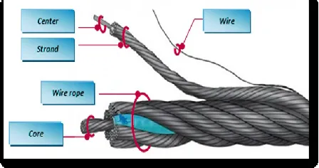
A steel wire rope has three basic components that vary in complexity according to specific applications: strands are laid around a central core in a helical position; each strand consists of a number of cold-drawn wires [1] that are helically served around central core. Figure 1 shows a schematic representation of wire rope construction. Due to this specific geometry the wire rope exhibits a high bending flexibility and large internal damping capableof resisting high tensile loads and permits the wire ropes to resume loads despite the break of one or more wires [2].
Figure 1. Steel wire rope Components
Despite all the advantages that this conception represents, it is an accepted fact that wire ropes are consumable with a limited life and it should be replaced before the risk of failure becomes unfortunate.
International Journal of Research (IJR)
e-ISSN: 2348-6848, p- ISSN: 2348-795X Volume 2, Issue 06, June 2015Available at http://internationaljournalofresearch.org
fraction of life βc. Such a study could be beneficial for manufacturers due to its low cost and simplicity
II. Material and experimental procedure
II.1 Material
Our purpose is to study the behavior of a strand belonging to a steel wire rope of type 19x7 (includes 19 strands with each strand
consisting of 7 individual wires)
andantigyratory construction (1x7 + 6x7 + 12x7) (Figure 2); such a structure is composed of a number of strands that are laid up in opposite directions to produce a non-rotating effect [3].
Figure 2. Steel Wire Rope of type 19x7 and antigyratory construction (1x7 + 6x7 + 12x7)
The studied strands are composed of 7 wires each individual wire is arranged helically around a central wire to form a 7-wire strand.
II.2Experimental procedure
To obtain specimens of the strand, a suitable length of the cable was cut and strands were de-wiring (wiring off). The minimum length of the samples strand is equal to the length of the test plus the necessary for the mooring. Therefore, a length of 300 mm is anticipated as the length of the test for the strands. The measurements tolerance in the length is ± a millimeter for all samples [4].
Dimensions of the strand are shown in Figure 3:
Figure 3. Dimensions of the studied strand
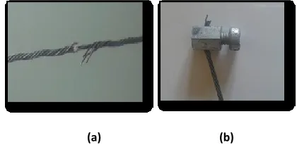
Tensile test of strand wire ropes of diameter 1,85 mm was realized at 5 virgin specimens to extract mechanical properties and 5 other samples which are artificially damaged by breaking 4/7 wires (Figure 4.a). The fixation of the samples is performed by means screwed wedges on both ends of the strand (Figure 4.b) in order to prevent sliding of the samples during the tests.
(a) (b)
Figure 4. a) Strand artificially damaged. b) Screwed wedges on the ends of the strand
The chemical composition
wasperformed in the Public Testing
Laboratory and Studies (LPEE) and the results are obtained by spectrometric analysis using a spectrometer peak spark.
III. Results of the experiments
III.1Chemical composition and mechanical properties
International Journal of Research (IJR)
e-ISSN: 2348-6848, p- ISSN: 2348-795X Volume 2, Issue 06, June 2015Available at http://internationaljournalofresearch.org
Table 1. Chemical composition of the material
It is noticed that the wire rope is made of a lowalloy steel with high percentage of carbon (about 1,478%); They are obtained by the cold wire-drawing process, which consists of passing the wire through a conical die until the desired diameter. Indeed, this reduction of diameter causes a hardening of the metal and then provides a high tensile strength.
Concerning Mechanical properties of the virgin strands extracted from tensile test curve [5], it is reported in the table.2:
Table 2 Mechanical properties of the material
III.2 Strength-elongation diagram
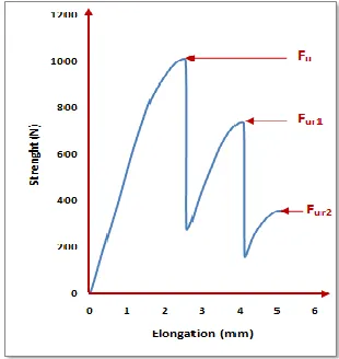
During the tensile test of a strand containing a number of broken wires, it is observed that the resistance drops at the rupture of each wire and resume its stiffness until the final break. The test curve of the applied strength in function of the elongation for the strand with 4 broken wires artificially damaged is given by the (Figure 5).
Figure 5.strength-elongation diagram for the strand with 4 wires artificially broken
According to figure 5, the studied strand has a residual ultimate force of 1008 N which drops to each failure of each wire constituting the strand then resumes its stiffness, until the final break value of 362 N corresponding to the last wire. This could be interpreted by the fact that during the test there is a loss of resistance depending upon the number of broken wires. The values of residual ultimate force are listed in Table 3.
Table 3. Values of residual ultimate force III.3 Calculation of static damage
The model of static damage (Ds) is to determine the evolutions of the force whose variations are mainly due to damage. Then we quantify the damage by the variable Ds expressed as:
𝐷𝑠 =
1−𝐹𝑢𝑟 𝐹𝑢 1−𝐹𝑎 𝐹𝑢
Where:
Fu: the value of the maximum ultimate strength
Elements C Si Mn P S Cr Mo
% 1,478 2,04 2 0,091 0,0144 0,182 0,208
Young's
modulus
Poisson's
ratio
elastic limit
( MPa)
Breaking
stress (MPa)
E=189 GPa ν=0,3 σe=1035 σr=1992
Fu (N) Fur1 (N) Fur2 (N)
1008 740 362
International Journal of Research (IJR)
e-ISSN: 2348-6848, p- ISSN: 2348-795X Volume 2, Issue 06, June 2015Available at http://internationaljournalofresearch.org
Fur: the value of the ultimate strength
Fa: the force just before the final break
Throughout the test, we are following the phenomenon of damage from the initial state with 4 wires artificially damaged to the complete rupture of the specimen by measuring the ultimate residual force in function of the life fraction β that corresponds to ratio of the number of broken wires on the total number of wires, this phenomenon is described by the damage parameter Ds Equation (1) and presented in figure 6.
And we have:
In the initial state until the failure of the first wire: : 𝛽 = 5/7→ Fur = Fu → D = 0
In the final state: 𝛽 = 1→ Fur = Fa →D = 1
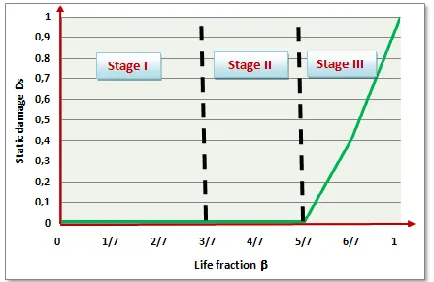
The variation of the static damage according to the life fraction is illustrated by the curve:
Figure 6. Evolution of the static damage depending on the life fraction
The increase of the damage means the loss in static tensile strentgh, this loss is changing when the number of broken wire becomes more important. Itis a fragile behavior of materialwith irreversible deformation that reduces the ultimate force of the material.
From Figure 6, we could distinguish only the stage III (previously indicated in [5] for strand with 2 broken wires). The stage III corresponds to the brutal damage. This indicates that a strand with 4 broken wires is located in stage III of damage in the unstable zone that we could not control, so a predictive maintenance intervention is required.
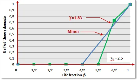
III.4 Calculation of damage using unified theory
The damage of the strand being progressive, its variation is influenced by the level of loading. Various representative theories of this damage are given initiated by the linear of Miner law; finding that the damage changes linearly depending on the fraction of life. [6]
By analogy with the unified theory, an empirical relationship describing the damage is proposed:
𝐷 =
𝛽𝛽 + 1−𝛽 [𝛾 −(𝛾 𝛾 𝑢 )8 𝛾 −1 ]
Where: β =Ni
Nt , γ = Fur
F0 andγu = Fu F0
F0 is the residual endurance limit that could be determined by multiplying the ultimate residual force by a coefficient α (for n = 0; F0 = α Fu).
For a coefficientα = 1
Safety factor of the strand
The variation of the damage according to β with γ as a parameter is shown in Figure 6. Each curve is associated to a loading level.
International Journal of Research (IJR)
e-ISSN: 2348-6848, p- ISSN: 2348-795X Volume 2, Issue 06, June 2015Available at http://internationaljournalofresearch.org
Figure 7 Evolution of Damage by unified theory and Miner law in function of the life fraction
The resulting curve is associated to a particular level of loading. This damage curve gradually approaches the bisector (linear rule of Miner) depending on the life fraction β.
IV. Conclusion
A damage study is conducted based on a simple static tensile test on a sample of strand extracted from steel wire rope of type 19x7 and antigyratory structure,4 of its wires were broken artificially, this study allows us to follow the damage at determined level of degradation and thereafter locate the damage degree relative to the critical life time, and thus to intervene at the appropriate time before the risk of failure becomes deplorable and catastrophic.
Two methods of damage calculation were used; the first experimental based on the results of the Strength-elongation diagram and the second theoretical using the unified theory and linear rule of Miner. It is concluded that a strand with 4/7 broken wires is in the unstable zone of damage and a dangerous brutal rupture could occur.
In industry, such studies have an interest in any company that regularly or occasionally use wire ropes, and have as objective a predictive maintenance of their systems to maintain the safety of personnel and prevent fatal and expensive accidents
related to the use of cables with a low cost based only on a simple tensile test.
References
[1] S. Das, J. Mathur, T. Bhattacharyya, S. Bhattacharyya. «Failure analysis of steel wire of grade LRPC during drawing process». Engineering Failure Analysis, 27
(2013), pp. 333–339
[2] A. Meksem, «Probabilistic approach and experimental characterization of the behavior of wire rope hoist», Ph.D. Thesis, ENSEM, University Hassan 2, Ain Chock, Casablanca, 2010.
[3] Kaczmarczyk S, Ostachowicz W. «Transient vibration phenomena in deep mine hoisting cables. Part 1: Mathematical model». Journal of Sound and Vibration 2003;
262:219–44.
[4] EN 10002-1: «Metallic materials – Tensile testing-Part 1: Method of test at ambient temperature»: European Standard : 2001 has the status of a DIN Standard
[5] N.Mouhib, H.Ouaomar, M.Lahlou, A.Ennaji, M. El Ghorba: «Tensile test of a strand with 2 broken wires artificially damaged and life prediction » The International Journal Of Engineering And Science (IJES), Vol.4, Issue .4 ,Pages
,PP.11-16, 2015 .ISSN (e): 2319 – 1813
ISSN (p): 2319 – 1805