Simulation and Implementation of Multilevel
Inverter Based BLDC Motor Drive
Ninu Joy
1, Minam Nangkar
2, Muhammed Nabeel U P
3, Preshobe P
4, Priyana Ann George
5Assistant Professor, Dept. of EEE, MA College of Engineering, Kothamangalam, Kerala, India 1
UG Student, Dept. of EEE, MA College of Engineering, Kothamangalam, Kerala, India2
UG Student, Dept. of EEE, MA College of Engineering, Kothamangalam, Kerala, India 3
UG Student, Dept. of EEE, MA College of Engineering, Kothamangalam, Kerala, India 4
UG Student, Dept. of EEE, MA College of Engineering, Kothamangalam, Kerala, India5
ABSTRACT: In high power high voltage application BLDC motor are widely used because of higher efficiency, simple in construction, lower cost, less in maintenance and higher torque or high output power per unit volume. For driving the BLDC motor an electrical commutator (inverter) is required. PWM inverter gives good performance. In two level inverter there are problems of harmonics distortions. The increase in the number of steps in voltage is one of the solutions for the above problems. This can be possible by using multilevel inverters. The conventional method produces high switching losses, results in poor drive performance.This paper proposes an effective replacement for this. The effectiveness of the neutral clamped multilevel inverter based drive system is verified through simulation using MATLAB simulink package.
KEYWORDS: BLDC Motor, Neutral Point Clamped Diode, Multilevel Inverter, Multicarrier PWM, THD
I.INTRODUCTION
BLDC motor offers many advantages including high efficiency, low maintenance, reduced weight and more compact construction. The BLDC motors have been widely used for various industrial application based on inherent advantages. They are the most suitable motors in application field with requiring fast dynamic response of speed, because they have high efficiency and can be easily controlled in a wide speed range. Multi-Level Inverter (MLI) topologies have been widely used in the motor drive industry. The advantage of the three-level topology is that multilevel voltage waveforms can be synthesized using devices with lower voltage ratings. Multilevel Inverters generate sinusoidal voltages from discrete voltage levels and Pulse Width Modulation (PWM) strategies accomplish this task of generating sinusoids of variable voltage and frequencies. Sinusoids of three phases for different voltages are generated by providing different gate signals to the MOSFETs. Several techniques for implementation of PWM for inverters have been developed. The two main techniques of PWM generation for multilevel inverters are Sine-Triangle PWM (SPWM) and Space Vector PWM (SVPWM). Multilevel Sine Triangle PWM involves comparison of a reference signal with a number of level shifted carriers to generate the PWM signal.
in cascade etc are discussed. A Purna Chandra Rao et.al [3]proposed that in high power high voltage application BLDC motor are used widely . PWM inverter gives good performance . In two level inverter there are problems of harmonics distortions, low electromagnetic interference , high DC link voltage required, higher dv/dt , heating of rotor (rotor shaft) etc. In this paper PWM control, variable DC link control, hysteresis control techniques are discussed. S.Flora Viji Rose1 et. Al[4] proposed that the 3 phase diode clamped multilevel inverter fed induction motor is described in this paper. Speed is controlled here using the v/f method which is the most efficient one . Speed is controlled by adjusting the magnitude of stator voltage and frequency keeping the air gap flux constant. The conventional method was found to have certain limitation like the switching losses. Here in multilevel inverter circuit it is overcome.3 level approach is used here so that harmonic reduction and high dc link voltage is obtained. The demerits of pulse width modulation was analyzed and multi carrier phase width modulation technique method of gate pulse generation was dealt with. The sample simulation results were also studied.Steffen Sernet et. al [5] presents a review of the state of the art and developments of 2L and multilevel VSCs for high power drive applications. The analyzed operating principles, relevant characteristics, establishment modulation techniques and latest developments were dealt with in detail. All the topologies (2L,VSCs,NPC,CHB and FC multilevel VSCs) were featured. The topic of consideration our project that is the neutral point clamped circuit was studied.
In this paper, a three-phase diode clamped multilevel inverter fed BLDC motor is described. The diode clamped inverter provides multiple voltage levels from a series bank of capacitors .The voltage across the switches has only half of the dc bus voltage. These features effectively double the power rating of voltage source inverter for a given semiconductor device . The proposed inverter can reduce the harmonic contents by using multicarrier PWM technique. It generates motor currents of high quality. Here the speed of a BLDC is precisely controlled by using three level diode clamped multilevel inverter.
II.DRIVE SYSTEM DESCRIPTION
Fig.1 3 Level Inverter Circuit Configuration
To produce a staircase-output voltage, consider one leg of the three-level inverter, The steps to synthesize the three-level voltages are as follows. For an output voltage three-level Vao=Vdc/2, turn on all upper-half switches A1 and A2. For
an output voltage level Vao=0, turn on one upper switch A2 and one lower switch A1’. 3. For an output voltage level Vao=-Vdc/2, turn on all lower half switches A1’ and A2’.
III.PROPOSED SCHEME
The block schematic of multilevel inverter fed three phase induction motor is as shown in Fig.2. The complete system will consist of two sections; a power circuit and a control circuit. The power section consists of a power rectifier, filter capacitor, and three phase diode clamped multilevel inverter. The motor is connected to the multilevel inverter. An ac input voltage is fed to a three phase diode bridge rectifier, in order to produce dc output voltage across a capacitor filter. A capacitor filter, removes the ripple contents present in the dc output voltage. The pure dc voltage is applied to the three phase multilevel inverter through capacitor filter. The multilevel inverter has 12 MOSFET switches that are controlled in order to generate an ac output voltage from the dc input voltage. The control circuit of the proposed system consists of three blocks namely microcontroller, opto-coupler and gate driver circuit. The microcontroller is used for generating gating signals required to drive the power MOSFET switches present in the multilevel inverter. The voltage magnitude of the gate pulses generated by the microcontroller is normally 5V. The controlled ac output voltage is fed to the BLDC motor drive.
Fig. 2 Block Diagram of Proposed System
IV.SIMULATED CIRCUITS AND WAVEFORMS
PWM Simulation Circuit
To control a three phase multilevel inverter with an output voltage of three levels; two carriers are generated and compared at each time to a set of three sinusoidal reference waveforms. One carrier wave above the zero reference and one carrier wave below the reference. These carriers are same in frequency, amplitude and phases; but they are just different in dc offset to occupy contiguous bands.
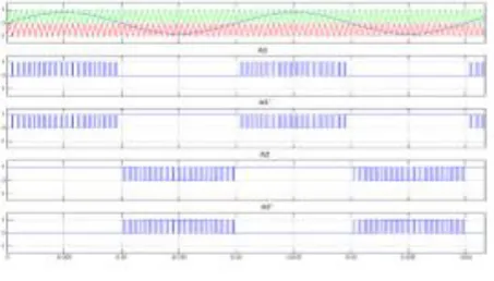
Fig.4. shows the output of the PWM simulation circuit. The waveform of sine-triangle intersection is obtaines as shown. Two carriers together with modulation signal have been used to obtain SPWM control. The gating pulses are generated using in-phase disposition technique.
Fig. 4 Gate pulses for leg A switches.
Multilevel Inverter Simulation Circuit
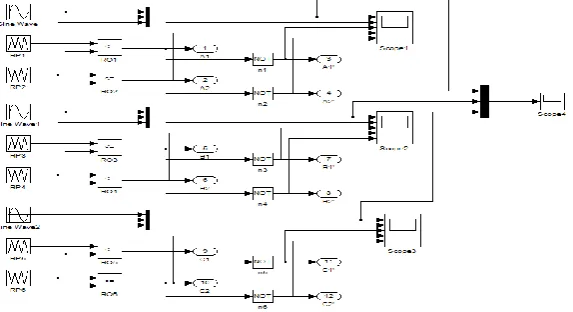
Simulation was performed in MATLAB. Simulated model for entire circuit is shown in Fig. 5. Here 12 MOSFETs are used for obtaining the inverter action. To view and study the line voltages scopes were used.
Fig. 5 Simulated Circuit
The output line-line voltage for a 3 level multilevel inverter system for a 50 Hz supply is obtained as the output of the 3 level inverter circuit simulation output . The resulting waveform is shown below.
V. RESULT AND DISCUSSION
The circuit for hardware implementation was designed using the software ORCAD. The gate triggering switching sequence was developed and the program for the same was developed in micro C and was burnt into the PIC16F7878. The circuit board was developed using PCB fabrication technique and the component were soldered and different speed were obtained and was displayed in a LCD. The different speeds obtained were found to be in the range between 600 rpm and 900 rpm. Also simulation was done to obtain the PWM wave and output of the three level multilevel inverter system.
VI.CONCLUSION
In this paper a diode clamped multilevel inverter has been presented for BLDC motor drive applications. The multicarrier PWM technique can be implemented for producing low harmonic contents in the output, hence the high quality output voltage was obtained. The modeling of three level BLDC motor drive was done and simulated using Simulink. The total harmonic distortion is very low compared to that of classical inverter. The different speeds obtained for BLDC motor were found to be in the range between 600 rpm and 900 rpm. The inverter system can be used for industries where the adjustable speed drives are required and significant amount of energy can be saved as the system has less harmonic losses. Also the number of levels may be incremented so as to reduce the amount of harmonic distortion further.
REFERENCES
[1] Yousif Ismail Al Mashhadany , “High-performance multilevel inverter drive of brushless DC motor”, International Journal of Sustainable and Green Energy, Vol. 4, pp 1-7, October 2014
[2] P. Devi Kiran, M. Ramachandra Rao, “Two Level and Five Level Fed BLDC Motor Drive”, International Journal of Electrical and Electronics, Vol. 3, Issue 3, pp 71-82, August 2013
[3] A. Purna Chandra Rao,Y.P. Obulesh, Ch. Sai Babu, ”High Performance Cascaded Multilevel Inverter fed BLDC Motor Drive”, International Journal of Engineering Sciences and Emerging Technologies, Vol. 5, Issue 2, pp: 88-96, June 2013
[4] S.Flora Viji Rose1, Mr.B.V.Manikandan , “Simulation and Implementation of Multilevel Inverter Based Induction Motor Drive”, International conference on control automation and energy conservation, Chennai 4-6 June 2009