Voltage and Current Harmonics Minimization in
Single Phase Sine Wave Voltage Source Inverter
Using Neuro -Fuzzy Controller
N.M.Spencer Prathap Singh1, Dr.N.Kesavan Nair2
Assistant Professor, Dept. of EEE, C.S.I, Institute of Technology, Thovalai, Kanyakumari, Tamilnadu, India1 Professor, Dept. of EEE, C.S.I, Institute of Technology, Thovalai, Kanyakumari, Tamilnadu, India2
ABSTRACT: This Paper Presents harmonic reduction in a voltage source inverter using Adaptive Neuro-Fuzzy controller. This soft computing tool is a combination of both neural networks and fuzzy logic .It provides accurate solutions compared to classical techniques. A full-bridge inverter is modelled using L-C filter connected to a load resistance and its performance is simulated using the artificial intelligences of fuzzy and neuro-fuzzy controllers. In the neuro –fuzzy controller the fuzzy sets and rules are adjusted using neural network tuning techniques. It is observed that in the sine wave inverter, voltage harmonics remain constant and the current harmonics reduces considerably in the Neuro-fuzzy controller compared to fuzzy controller with respect to Line and Load variations.
KEYWORDS: single phase full bridge inverter, THD, Fuzzy Logic Controller, Neuro-Fuzzy Logic Controller, Line regulation, Load regulation.
I.INTRODUCTION
An inverter is a power converter which converts DC input voltage into an AC output voltage. It is a static converter uses semiconductor power devices without any rotating parts or mechanical switches. The inverter incorporates switching control circuit which provides necessary pulses to the static switches for its turning ON and turning OFF with respect to correct timing and sequence. These switches are repetitively operated in such a way that the DC source at the input terminals of the inverter appears as AC at its output terminals. Inverters are normally used in adjustable speed AC motor drives, standby power supplies, traction, HVDC, grid connection of renewable energy sources uninterruptible power supplies (UPS), induction heating, etc.
In an inverter the sinusoidal output AC waveform is most widely preferred for many applications. However, the AC output of practical inverters have a certain amount of harmonics .Due to the presence of harmonics in an inverter, it creates excess heating, reduces reliability of equipments, interferences, reduced efficiency, etc. There are two practical ways by which the harmonic can be brought down to a low value within acceptable limits. One method is to use a filter circuit on the output side of the inverter. The second method employs pulse width modulation strategy.
Several such strategies have been developed for mitigating harmonics in an inverter. In sinusoidal pulse width modulation (SPWM), the residual harmonic content in the output voltage will be at high frequencies, and a filter circuit, if at all required, will be small. The harmonic content in the voltage is dependent on the type of load on the AC side. The harmonics of both voltage and current can be reduced using voltage and current observers in a modelled full bridge voltage source inverter [1, 2] .Many researchers suggest techniques such as optimum switching angles and Optimization methods. Moreover Adaptive Neuro-Fuzzy Inference system (ANFIS) technique was implemented in many fields such as Load forecasting, Transient control of inverters, Filter control, STATCOM control and FPGA control of inverters [3-9].Support vector mechanism, Harmonic injection methods, Droop controllers and increasing pulse number in the inverter are also suggested for mitigating harmonics in voltage source inverters.[10-15].
In this paper a single phase sine wave voltage source inverter is considered for suppressing harmonics using Neuro-fuzzy controller under line and Load variations. It is observed that Neuro-fuzzy controller acts effectively for reducing harmonics well compared to the Fuzzy logic controller.
II. BLOCK DIAGRAM REPRESENTATION AND LINEARIZED MODEL
Fig.1 .Block diagram representation of Single Phase Voltage Source Inverter
Fig.1 shows the basic block diagram representation of a full bridge voltage source inverter .In order to maintain the fundamental component at the desired level; a voltage control circuit is built with an inverter. The output of the inverter is fed to an LC filter which introduces a lag varying with the load impedance for producing oscillations. This block is also known as Tank Circuit. The load output is then fed to a suitable intelligent controller and the controlled output is compared with the reference signal and the error signal generated is used to reduce the harmonic content of single phase inverter.
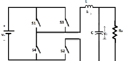
Fig.2 Circuit diagram of single phase full bridge voltage source inverter
Fig 2 shows the popular dc-ac inverter of full bridge topology. The switching scheme determines the frequency of the output ac waveform. The output voltage amplitude is controlled by varying the amplitude of the source voltage. The steady-state inverter operation can be explained by assuming two circuit modes with control variable U€ {0, 1}.Switches S1 and S2 are on, when U=1. Switches S3 and S4 are on, when U=0. The direction of load
current and load voltage reverses as the sequence of firing set of power switches are reversed.
The state space model for a single phase full bridge inverter is formulated by merging the circuit modes with control variable.
Let .
i L = Rate of change of current through the filter inductance with time.
.
V c = Rate of change of voltage across the filter capacitance with time.
L = Filter inductance in Henrys. C = Filter Capacitance in Farads. Ro= Load resistance in ohm.
Vin = Input dc Voltage in Volts.
Vc = Voltage across filter Capacitance in Volts.
.
iL = Vc + --- (1) .
Vc= iL- - --- (2)
III. PROPOSED METHOD
The performances of Fuzzy and Neuro-fuzzy control algorithms are verified by simulation. The simulation is performed in time domain for line and load regulation of single phase full-bridge voltage fed inverter. The switching frequency of the inverter is taken as 7.69 KHZ. The Specification for the 1-Phase inverter is listed in Table.1 [2]. Table.1- List of Inverter Specification for Simulations
Parameters Values
Input DC Voltage, Vin 15V
Load resistance,R0 50 Ω
Filter Inductance ,L 2 mH Filter Capacitance, C 500 µF Reference Signal, Vref 5V Sine,50 Hz
A. Estimation of Voltage and Current Harmonics in Voltage Source Inverter Using Fuzzy Logic controller
Fig.3. Basic Configuration of Fuzzy Logic Controller
The fuzzy controller consists of five basic modules namely fuzzifier, data base, rule base, decision maker and defuzzifier. The inputs of the fuzzy controller are the error and the change of error.
1. The fuzzification interface involves the following functions. (a) Measures the values of input variables.
(c) Performs the function of fuzzification that converts input data into suitable linguistic values. 2. The knowledge base consists of database and a linguistic control rule base.
(a) The database provides necessary definitions, which are used to define linguistic control rules.
(b) The rule base characterizes the control goals and control policy of the domain experts by means of a set of linguistic control rules.
3. The decision-making logic is the kernel of an FLC. It has the capability of simulating human decision-making based on fuzzy concepts and of inferring fuzzy control actions employing fuzzy implication and the rules of inference in fuzzy logic.
4. The defuzzification interface performs the following functions.
(a) A scale mapping, this converts the range of values of output variables into corresponding universe of discourse. (b) Defuzzification, which yields a non-fuzzy control action from an inferred fuzzy control action.
Thus the idea behind the FLC is to fuzzify the controller inputs, and then infer the proper fuzzy control decision based on defined rules. The output is then produced by defuzzifying this inferred control decision.
The standard Gaussian membership function is used in the fuzzy logic.The class of Gaussian membership functions is shown in Fig.4. It is given by
Ai(xi)=(-(ci-xi) 2
/2i 2
)...( 3)
Where ci and i are the center and width of the ‘i’th fuzzy set Ai respectively.
Fig.4 Gaussian membership functions
The Matlab/Simulink tool is applied for simulation.Fig.5 shows the simulink model of fuzzy logic Controller for reducing total harmonic distortion.
Fig.5 Simulink model of a Voltage Source Inverter Using Fuzzy Logic Controller
Percentage THD Values of Voltage and Current Harmonics are estimated using the Simulink blocks. The response Curves of Voltage and Current Harmonics of Single Phase Inverter are plotted.
0 0.01 0.02 0.03 0.04 0.05 0.06 0.07 0.08 0.09 0.1
-20 -15 -10 -5 0 5 10 15 20 Time (s) V o lt a g e ( V )
Fig.6.Variation of Voltage Harmonics with time using Fuzzy Controller
Fig.6 shows the output voltage waveform for a single phase voltage source inverter using Fuzzy Controller for reducing voltage harmonics. It is observed that the sinusoidal output voltage is obtained with reduced distortions. The output voltage magnitude remains constant without overshoots.
0 0.01 0.02 0.03 0.04 0.05 0.06 0.07 0.08 0.09 0.1
-1 -0.8 -0.6 -0.4 -0.2 0 0.2 0.4 0.6 0.8 1 Time (s) C u rr e n t (A )
Fig.7 Variation of Current Harmonics with time using Fuzzy Controller
Fig.7 Shows output current waveform with reduced current harmonics in a Single phase Voltage Source inverter using FLC.It is clear that the current waveform has initial overshoots and oscillations.The FLC acts effectively and minimizes the overshoots and the waveform becomes steady reduced with distortions.
B. Estimation of Voltage and Current harmonics in Voltage Source inverter using Neuro-Fuzzy Logic Controller
The fusion of ideas from fuzzy control and neural networks had acknowledged a significant role in improving controller performances. This integration of two controller’s forms Adaptive network based Fuzzy logic controller which modifies the characteristics of the rules, fuzzy sets and the structure of the control system. Neuro-Fuzzy controller is designed based on an average state space model of the classical Inverter. The design of Neuro- Fuzzy Logic Controller needs a good knowledge of the system operation. The steps involved in the design of Neuro - Fuzzy Logic Controller are Identification of inputs and outputs, Fuzzifying the inputs and outputs, development of rule base and Defuzzification .Fig.9 shows the simulink model of Single phase inverter using Neuro-fuzzy controller for reducing Total harmonic distortion.
The FALCON can be constructed from training examples by neural learning techniques and the constructed structure can be trained to develop fuzzy logic rules and determine proper input-output membership function. Expert knowledge can also be incorporated into the FALCON. The rule base of constructed structure contains fuzzy IF-THEN rules of sugeno’s first order type in which the output of each rule is a linear combination of input variables plus a constant term. For a first-order sugeno fuzzy model the common rule set with two fuzzy IF-THEN rules is the following.
Rule 1: If x is A1 and y is B1 then f1 = p1x +q1y+r1
Rule 2: If x is A2 and y is B2 then f2= p2x +q2y+r2
The final output is the weighted average of each rule’s output. The architecture of the Adaptive Neuro-fuzzy Inference System (ANFIS) is shown in Fig.8.Consider a first-order sugeno fuzzy model with two input x and y and one output with above-mentioned fuzzy IF-THEN rules.
A w wi
Fig.8 Architecture of the Adaptive Neuro-fuzzy Inference System (ANFIS) System has a total of five layers.
Layer 1:
Every node I in this layer is an adaptive node performing membership function. O1,i =Ai (xi) i=1,…n. ... ( 4)
Where xi is the input to node i.
The membership function can be any appropriate parameterized membership function. Parameters in this layer are referred to as premise parameters.
Layer2:
Every node in this layer is a fixed node whose output is the product of all the incoming signals. (i.e.) these nodes perform the fuzzy AND operation.
O2,i =wi =Ai(xi).Bi(y) i=1,…n. ----(5)
Each node output represents the firing strength of a rule.
Layers 3:
The nodes of this layer calculate the normalized firing strength of each rule.
O3,i =wi =wi /iwi i=1,…n ... (6)
wi –firing strength of a rule.
Layer 4:
Every node i in this layer is an adaptive node with a node function.
x
f
y
y
x
NN
N
N
N
N
N
O4,i =wi fi=wi (pix+qiy+ri) i=1,…n. ... (7)
Where wi a normalized firing strength from layer 3 and {pi,qi,ri} the parameter set. Parameters in this layer are
referred to as consequent parameters.
Layer5:
The single node in this layer computes the overall output as the summation of all incoming signals. O5,1 =wifi =Iwifi /Iwi i=1,…n. ... (8)
Where O l,i denote the output of the ‘i’th node in layer l. This structure can update membership functions and
rule base parameters accordingly to the gradient descent update procedure.
Fig.9-Simulink model of a Voltage Fed Inverter Using Neuro- Fuzzy Controller
The Simulink block diagram of an UPS Inverter with Neuro- Fuzzy Logic Controller is shown in Fig. 9.Here the 15V sine wave reference signal is applied to a Comparator where it is compared with the feedback signal. The error and change in error of two inputs are fed to the Neuro-Fuzzy controller. The Neuro-Fuzzy controller output tune the Power switches and reduces the harmonic distortion.
0 0.01 0.02 0.03 0.04 0.05 0.06 0.07 0.08 0.09 0.1
-20 -15 -10 -5 0 5 10 15 20
Time (s)
V
o
lt
a
g
e
(
V
)
Fig.10- Variation of Voltage Harmonics with time using Neuro-Fuzzy Controller
0 0.01 0.02 0.03 0.04 0.05 0.06 0.07 0.08 0.09 0.1 -1
-0.8 -0.6 -0.4 -0.2 0 0.2 0.4 0.6 0.8 1
Time (s)
C
u
rr
e
n
t
(A
)
Fig.11- Variation of Current Harmonics with time using Neuro- Fuzzy Logic Controller
Fig.11shows Output current waveform with reduced current harmonics in a single phase voltage Source inverter using Neuro-fuzzy Logic Controller. The response shows that the current harmonics are initially underdamped in nature and settled to a steady state with constant magnitude, due to the sudden action of the controller.
IV. TEST RESULTS AND DISCUSSIONS
Experimental investigations have been performed for the various input voltages and load conditions to the single phase inverter using Fuzzy Logic and Neuro-Fuzzy controllers and its performances were compared.
A. Estimaton of Percentage THD using Fuzzy and Neuro-fuzzy Controller by input Voltage Variations (Line regulation)
Table.2- Output Voltage THD Subjected to a Variation of Input Voltages from 12V to 20V using Fuzzy and Neuro-fuzzy Controllers for fixed RO=50 Ω
Table.3- Output Current THD Subjected to a Variation of Input Voltages from 12V to 20V using Fuzzy and Neuro-fuzzy Controllers for fixed RO=50 Ω
Vin (Volts)
%THD v
Fuzzy Neuro-Fuzzy 12 0.729 0.732 13 0.780 0.777 14 0.780 0.780 15 0.780 0.781 16 0.780 0.781 17 0.780 0.781 18 0.780 0.781 19 0.780 0.781 20 0.780 0.781
Vin (Volts)
%THDi
B.Estimation of Percentage THD using Fuzzy and Neuro-fuzzy Controller by Load Variations (Load regulation)
Table.4- Output Voltage THD Subjected to a Variation of Load resistances from 46Ω to 53Ω using Fuzzy and Neuro-fuzzy Controllers for fixed Vin =15V
Table.5- Output current THD Subjected to a Variation of Load resistances from 46Ω to 53Ω using Fuzzy and Neuro-fuzzy Controllers for fixed Vin =15V
%THDi Ro
(Ω)
FUZZY Neuro Fuzzy 46 0.2643 0.3001 47 0.2872 0.2873 48 0.3011 0.2816 49 0.3031 0.2830 50 0.3206 0.2909 51 0.3408 0.3039 52 0.3624 0.3206 53 0.3843 0.3397
Table: 6 .comparison statement of THD’s for fixed vaues of RL=50Ω and Vin=15V
S.NO Case %Voltage THD
%Current THD 1 Fuzzy
Controller
0.7809 0.3206 2 Neuro Fuzzy
Controller
0.7812 0.2909
The harmonic content in the full bridge Inverter was mitigated using the intelligent controllers of fuzzy logic and neuro-fuzzy .From the above tables, it is observed that the THD values are better in the sine wave Inverter using neuro-fuzzy controller.
%THDv
Ro
V. CONCLUSIONS
MATLAB Simulation was performed for a single phase voltage source Full bridge Inverter and it is Observed that Neuro- Fuzzy Logic Controller provides reduced Voltage and Current THD Values lesser than 5% as per the guidelines given in the IEEE standard 519-1992 under Line and Load variations.
REFERENCES
[1] Kamakshy Selvajyothi and Panappakkam Arumugam Janakiraman,” Reduction of voltage Harmonics in single phase Inverters,” IEEE Trans.on Power Del .Vol.25,No.2,pp.1045-1057,Apr.2010.
[2] Fei-Hu Hsich, Po- LUN Chang, Ying- Shiuchen, Hen- Kung Wang, YonqJonq- Chin Hwang,” Fast- Scale Instability Phenomena and Chaotic Control of Voltage Control Single- Phase Full–bridge Inverter Via Varying Load resistance,” ICIEA, pp.3422- 3427,2009 [3] Saravanasankar and D.Sivabalan, ”Elimination of Harmonics in cascaded multilevel inverter using soft computing
technique,”International Journal of Engineering Research and Science and Technology, Vol.1,No.2, pp.75-84,April 2015.
[4] T.R.Sumithra and A.Nirmal Kumar, ”Elimination of Harmonics in multilevel inverters connected to solar photovoltaic systems using ANFIS:An Experimental case study,”Journal of Applied Research and Technology.Vol.11,No.1, pp.124-132, Feb.2013.
[5] Suhas B.Karwade and Dr.M.S.Ali,”Review paper on Load Forecasting using Neuro fuzzy System,”IOSR-Journal of Electrical and Electronics Engg,Vol.10,No.3,pp.38- 42,June2015.
[6] N.Bhoopal and G.Venu madhav,”Neural and Neurofuzzy controllers for UPS inverter applications,”International Journal of Recent trends in Engineering. Vol.20,No.8,pp.45-49 ,Nov.2009.
[7] N.K Bett,J.N. Ndreu,P.K.Hinga,” Adaptive Neuro-Fuzzy Inference system based control of Three phase hybrid power filter for harmonic mitigation,”International Journal of Emerging Technology and Advanced Engineering, Vol.2,No.8,pp.75-81,Aug.2012
[8] Subir Datta and Anjan Kumar Roy,”ANFIS based 48-pulse STATCOM Controllers for Enhancement of power system stability, ”International Journal of Modeling and optimization,Vol.2,No.4,pp.455-461,June 2012.
[9] Dharmik N.Mehta,Nilesh N.Kasat, ”Neurofuzzy based inverter implement with FPGA,”Internatinal Journal of Advanced Research in computer and communication Engineering,Vol.3,No.1,pp.4940- 4943, Jan.2014
[10] Veerakumar,Nirmal Kumar,Sathish Kumar,Rajesh ”Novel Harmonic Elimination Technique for cascaded H bridge inverter using sampled reference frame,”Journal of Theoretical and Applied Information Technology, Vol.58, No.2,pp.421-42,
Dec.2013.
[11 G.Nageswara Rao,Dr.Sangameswara Raju, Dr.K.Chandrasekhar, ”Support Vector machine(SVM) and Fuzzy based Hybrid Feedback Technique for Harmonic Elimination of multilevel inverter ”Proceedings of international conference on Advances in Electrical and Electronics AETAEE, pp.832-848, 2013.
[12] Aridam Dutta,Tirtharaj Sen, S.Sengupta,”Reduction in Total Harmonic Distortion in a Non-Linear Load with Harmonic injection method,”International Journal of Recent Trends in Engg.,Vol.1,No.4,pp.85-89,May 2009.
[13] Quing-chang Zhong,Harmonic Droop Controllers to Reduce the Voltage Harmonics of Inverters,IEEE Trans.on Industrial Electronics, vol.60,No.3, pp.936-945,Mar.2013.
[14] Karl Kaiser,”Operational cost Avoidance through Harmonic mitigation in Industrial Environments, ”Schnerder Electric White paper,Vol.1,N0.1,pp.1- 10,2013.
[15] P.Tamilvani,K.R.Valluvan,”Harmonic mitigation in various Levels of multilevel inverter with different Loads, ”International’ Journal of Innovative Research in Electrical, Electronics, Instrumentation and control Engineering, Vol.2,No.9,pp.1989-1996, Sep.2014
BIOGRAPHY
N.M. Spencer Prathap Singh is working as Assistant professor and Head at the Department of Electrical and Electronics Engineering in CSI Institute of Technology, Thovalai, Kanyakumari District, TamilNadu, India. He completed his B.E (Electrical and Electronics Engineering) From Manonmanium Sundaranar University in 1998. He completed his M.Tech (Control Systems) from Kerala University in 2005. He is a life member of ISTE. His area of interest includes Electromagnetism, control systems and power Electronics and Drives. He is currently a Ph.D scholar in the field of power Electronics and Drives at the Anna University, Tamil Nadu, India. He is a member of IEEE. He organized various conferences, seminars and workshops.