© 2013, IJCSMC All Rights Reserved 128 Available Online atwww.ijcsmc.com
International Journal of Computer Science and Mobile Computing
A Monthly Journal of Computer Science and Information Technology
ISSN 2320–088X
IJCSMC, Vol. 2, Issue. 9, September 2013, pg.128 – 138
RESEARCH ARTICLE
Design and Performance Analysis of
Various Adders using Verilog
Maroju SaiKumar
1, Dr. P. Samundiswary
2¹Student, Department of Electronics Engineering, Pondicherry University, Pondicherry, India
²Assistant Professor, Department of Electronics Engineering, Pondicherry University, Pondicherry, India
1
[email protected]; 2 [email protected]
Abstract—Adders are one of the most widely digital components in the digital integrated circuit design and are the necessary part of Digital Signal Processing (DSP) applications. With the advances in technology, researchers have tried and are trying to design adders which offer either high speed, low power consumption, less area or the combination of them. In this paper, the design of various adders such as Ripple Carry Adder (RCA), Carry Skip Adder (CSkA), Carry Increment Adder (CIA), Carry Look Ahead Adder (CLaA), Carry Save Adder (CSA), Carry Select Adder (CSlA), Carry Bypass Adder (CByA) are discussed and the performance parameters of adders such as area and delay are determined and compared. Various adders are designed using Verilog HDL. Then, they are simulated and synthesized using Xilinx ISE 13.2 for Virtex-6 family device with speed grade -2.
Keywords— Ripple Carry Adder; Carry Skip Adder; Carry Increment Adder; Carry Look Ahead Adder; Carry Save Adder; Carry Select Adder; Carry Bypass Adder; FPGA; Xilinx ISE
I. INTRODUCTION
Arithmetic unit are the essential blocks of digital systems such as Digital Signal Processor (DSP), microprocessors, microcontrollers, and other data processing units. Adders become a critical hardware unit for the efficient implementation of arithmetic unit. In many arithmetic applications and other kinds of applications, adders are not only in the arithmetic logic unit, but also in other parts of processor. Addition operation can also be used in complement operations (1’s, 2’s, and so on), encoding, decoding and so on. In general, addition is a process which involves two numbers which are added and carry will be generated. The addition operations will result in sum value and carry value. All complex adder architectures are constructed from its basic building blocks such as Half Adder (HA) and Full Adder (FA).In this paper, an attempt has been made to design and simulate the different types of adders using Verilog language and Xilinix ISE 13.2. Then the performance parameters of the various adders are calculated and compared. The rest of the paper is organised as follows: Section I deals with the introduction about adders. In section II, the designs and the features of various adders are discussed. And section III deals with the simulation and synthesis results of adders.
II. ADDERS
© 2013, IJCSMC All Rights Reserved 129 A. Ripple Carry Adder
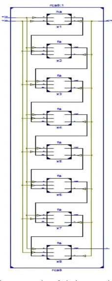
Ripple Carry Adder (RCA) is a basic adder which works on basic addition principle [1]. The architecture of RCA is shown in Fig 1.
Fig. 1 Architecture of Ripple Carry Adder (RCA)
RCA contains series structure of Full Adders (FA); each FA is used to add two bits along with carry bit. The carry generated from each full adder is given to next full adder and so on. Hence, the carry is propagated in a serial computation [1]. Hence, delay is more as the number of bits is increased in RCA.
B. Carry Skip Adder
As the name indicates, Carry Skip Adder (CSkA) uses skip logic in the propagation of carry [2]. It is designed to speed up the addition operation by adding a propagation of carry bit around a portion of entire adder. The carry-in bit designated as Ci. The output of RCA (the last stage) is Ci+4. The Carry Skip circuitry consists of
two logic gates. AND gate accepts the carry-in bit and compares it with the group of propagated signals [2].
Pi, Pi+3= (Pi+3)*(Pi+2)*(Pi+1)*Pi & Carry= Ci+4 + (Pi, i+3)* Ci. (1)
The architecture of CSkA is shown in Fig 2.
Fig. 2 Carry Skip Adder (CSkA) C. Carry Increment Adder
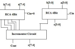
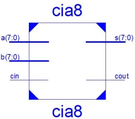
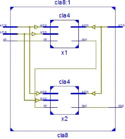
The design of Carry Increment Adder (CIA) consists of RCA’s and incremental circuitry [2]. The incremental circuit can be designed using HA’s in ripple carry chain with a sequential order. The addition operation is done by dividing total number of bits in to group of 4bits and addition operation is done using several 4bit RCA’s. The architecture of CIA is shown in Fig 3.
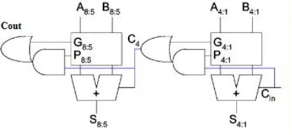
Fig. 3 Carry Increment Adder (CIA) D. Carry Look Ahead Adder
© 2013, IJCSMC All Rights Reserved 130
the generation values, propagation values are computed. Internal carry generation is calculated in second stage. And in final stage, the sum is calculated. The flow chart of CLA is given in Fig 4.1 and the architecture of CLA is given in Fig 4.2.
Fig. 4.1 Flow chart of Carry Look Ahead Adder (CLA)
Fig. 4.2 Architecture of Carry Look Ahead Adder (CLA)
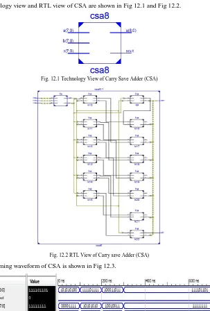
E. Carry Save Adder
In Carry Save Adder (CSA), three bits are added parallelly at a time. In this scheme, the carry is not propagated through the stages. Instead, carry is stored in present stage, and updated as addend value in the next stage [3]. Hence, the delay due to the carry is reduced in this scheme.
The architecture of CSA is shown in Fig 5.
Fig. 5 Carry Save Adder (CSA)
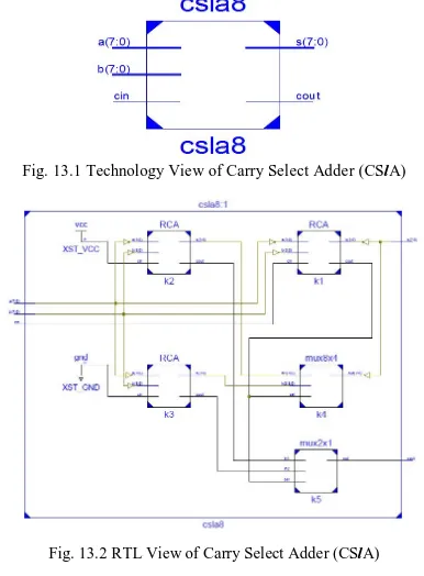
F. Carry Select Adder
Carry Select Adder (CSlA) architecture consists of independent generation of sum and carry i.e., Cin=1
and Cin=0 are executed parallelly [4]. Depending upon Cin, the external multiplexers select the carry to be
© 2013, IJCSMC All Rights Reserved 131 Fig. 6 Carry Select Adder (CSlA)
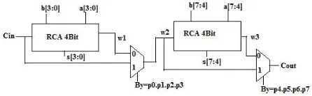
G. Carry Bypass Adder
In Carry Bypass Adder (CBA), RCA is used to add 4-bits at a time and the carry generated will be propagated to next stage with help of multiplexer using select input as Bypass logic. By pass logic is formed from the product values as it is calculated in the CLA. Depending on the carry value and by pass logic, the carry is propagated to the next stage [2].
The architecture of Carry Bypass Adder (CBA) is given in Fig 7.
Fig. 7 Carry Bypass Adder (CBA)
III.SIMULATION RESULTS
Various adders are designed by using Verilog HDL. Simulation and synthesis are done by using Xilinx ISE 13.2 for Virtex-6 family device with a speed grade of -2. In simulation results, Technology View describes top block which shows the set of inputs and outputs. Register Transfer Logic (RTL) view designates internal architectural blocks along with the connections between input and output pins. Timing waveform is generated by writing test bench program which contains the set of input test vectors applied to design.
A. Simulation Results of Ripple Carry Adder (RCA)
The technology view and RTL view of RCA are shown in Fig 8.1 and Fig 8.2.
© 2013, IJCSMC All Rights Reserved 132 Fig. 8.2 RTL View of Ripple Carry Adder
And, the timing waveform of RCA is shown in Fig 8.3.
Fig. 8.3 RTL View of Ripple Carry Adder B. Simulation Results of Carry Skip Adder (CSkA)
The technology view and RTL view of CSkA are shown in Fig 9.1 and Fig 9.2 and, the timing waveform of CSkA is shown in Fig 9.3.
© 2013, IJCSMC All Rights Reserved 133 Fig. 9.2 RTL View of Carry Skip Adder (CSkA)
Fig. 9.3 Timing Waveform of Carry Skip Adder C. Simulation Results of Carry Increment Adder (CIA)
The technology view and RTL view of CIA are shown in Fig 10.1 and 10.2 and, the timing waveform of CIA is shown in Fig 10.3.
© 2013, IJCSMC All Rights Reserved 134 Fig. 10.2 RTL View of Carry Increment Adder
Fig. 10.3 Timing Waveform of Carry Increment Adder
D. Simulation Results of Carry Look Ahead Adder (CLA)
The technology view of CLA is shown in Fig 11.1.
Fig. 11.1 Technology View of Carry Look Ahead Adder
The RTL view and timing waveform of CLA are shown in Fig 11.2 and Fig 11.3.
© 2013, IJCSMC All Rights Reserved 135 Fig. 11.3 Timing Waveform of Carry Look Ahead Adder
E. Simulation Results of CSA
The technology view and RTL view of CSA are shown in Fig 12.1 and Fig 12.2.
Fig. 12.1 Technology View of Carry Save Adder (CSA)
Fig. 12.2 RTL View of Carry save Adder (CSA)
And, the timing waveform of CSA is shown in Fig 12.3.
Fig. 12.3 Timing Waveform of Carry Save Adder (CSA) F. Simulation Results of Carry Select Adder (CSlA)
© 2013, IJCSMC All Rights Reserved 136 Fig. 13.1 Technology View of Carry Select Adder (CSlA)
Fig. 13.2 RTL View of Carry Select Adder (CSlA)
And, the timing waveform of CSlA is illustrated in Fig 13.3.
Fig. 13.3 Timing Waveform of Carry Select Adder (CSlA)
G. Carry Bypass Adder (CBA)
The technology view and RTL view of CBA is shown in Fig 14.1 and Fig 14.2.
© 2013, IJCSMC All Rights Reserved 137 Fig. 14.2 RTL View of Carry Bypass Adder (CBA)
And, the timing waveform of CBA is shown in Fig 14.3.
Fig. 14.3 Timing Waveform of Carry Bypass Adder (CBA)
H. Performance comparison of Various Adders
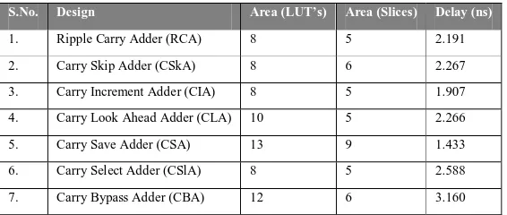
The performance comparison of various adders with respect to area and delay are given in Table 1.
TABLE I: Performance Analysis of Various Adders
S.No. Design Area (LUT’s) Area (Slices) Delay (ns)
1. Ripple Carry Adder (RCA) 8 5 2.191
2. Carry Skip Adder (CSkA) 8 6 2.267
3. Carry Increment Adder (CIA) 8 5 1.907 4. Carry Look Ahead Adder (CLA) 10 5 2.266
5. Carry Save Adder (CSA) 13 9 1.433
6. Carry Select Adder (CSlA) 8 5 2.588
7. Carry Bypass Adder (CBA) 12 6 3.160
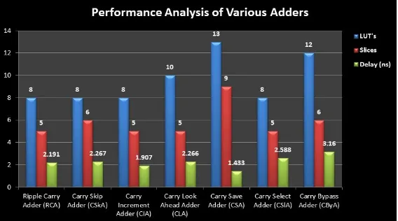
© 2013, IJCSMC All Rights Reserved 138 Fig. 15 Performance Analysis of Adders
IV.CONCLUSION AND FUTURE WORK
Various Adders are designed, simulated and synthesized using Verilog HDL in Xilinx ISE 13.2 for Virtex-6 Family with speed grade -2. It is concluded that, Carry Increment Adder achieves better performance in terms of area and delay compared to that of other adder topologies. In future work, it is needed to design unique adder which provides low area as well as delay in order to meet the needs of current VLSI industry. Further, this work can be extended by designing and simulating the adders with increased number of bits such as 16bits, 32bits and 64 bits.
REFERENCES
[1] Padma Devi, Ashima Girdher, and Balwinder Singh, Improved Carry Select Adder with Reduced Area and Low Power Consumption, International Journal of Computer Applications, vol.3, no.4, pp.14-18,June 2010. [2] R.Uma, Vidya Vijayan, M.Mohanapriya, and Sharon Paul, Area, Delay and Power Comparison of Adder
Topologies, International Journal of VLSI Design & Communication Systems, vol.3, no.1, pp.153-168,Feb 2012.
[3] Raminder Preet Pal Singh, Praveen Kumar, and Balwinder Singh, Performance Analysis of 32-Bit Array Multiplier with a Carry Save Adder and with a Carry Look Ahead Adder, Letters of International Journal of Recent Trends in Engineering, vol.2, no.6, pp. 83-89,Nov 2009.
[4] Sarabdeep Singh, Dilip Kumar, Design of Area and Power Efficient Modified Carry Select Adder, International Journal of Computer Applications, vol.33, no.3, pp.14-18,Nov 2011.
[5] Xilinx13.4, Synthesis and Simulation Design Guide, UG626 (v13.4) January 19, 2012 (2002); The IEEE website. [Online]. Available: http://www.ieee.org/
[6] Vaibhav Gupta, Debabrata Mohapatra, Anand Raghunathan, and Kaushik Roy, Low-Power Digital Signal Processing using Approximate Adders, IEEE Transactions on Computer-Aided Design of Integrated Circuits and Systems, vol. 32, no. 1, pp.124-137,Jan 2013.
[7] Shivani Parmar, Kirat Pal Singh, Design of High Speed Hybrid Carry Select Adder, Proceedings of IEEE International Conference on Advance Computing, Nanjing, China, pp.1656-1663, 2012.
[8] M.A. Raheem, Harsha Gupta, Dr.Kaleem Fatima, Osman Adil, A High Speed Reversible Low-Power Error Tolerant Adder, Asia Pacific Conference on Post Graduate Research in Microelectronics & Electronics, Hyderabad, India, pp.178-183, Dec 2012.
[9] Sauvagya Ranjan Sahoo, Kamala Kanta Mahapatra, Design of Low Power and High Speed Ripple Carry Adder using Modified Feed through Logic, Proceedings of IEEE International Conference on Communications, Devices and Intelligent Systems, West Bengal, pp.377-380, June 2012.