Dual UPQC Converter Grid Systems for Effective Regulation
of Load
1
Mr. Naresh Donthukurthi -P.G student
2Mr. Y.Veerraju -Assistant Professor,
Dept. of EEE, Nova College of Engineering & Technology, jntuk, jangareddygudam, AP
Abstract-This paper presents a simplified intelligent control technique for a dual three-phase topology of a unified power quality conditioner iUPQC. The i-UPQC is composed of two active filters, a series active filter and a shunt active filter (parallel active filter), used to eliminate harmonics and unbalances .This paper explains an enhanced Fuzzy controller for the dual topology of the unified power quality conditioner (iUPQC) expanding its pertinence in power quality compensation, and additionally in microgrid applications. Implementation of intelligence controller by using voltage as feedback for significantly improving the dynamic performance of UPQC, the comparative analysis of several control strategies fed UPQC for power quality improvement features is presented. Fuzzy control has emerged as one of the most active and prolific areas for research in the applications of fuzzy set theory, especially in the realm of industrial process, which do not lend of quantities data regarding the input-output relations. By using PI controller, beyond the conventional UPQC power quality features, including voltage sag/swell compensation, the iUPQC will also provide reactive power support to regulate not only the load-bus voltage but also the voltage at the grid-side bus. In other words, the iUPQC will work as a static synchronous compensator (STATCOM) at the grid side, while providing also the conventional UPQC compensations at the load or microgrid side. By using Fuzzy logic controller also we have the same functioning of iUPQC and additionally the harmonics are reduced. Here three different cases are taken into consideration considering loads. Comparison results are validated with the tabular form. Simulations results are provided to verify that fuzzy logic controller is better than PI controller using MATLAB/ SIMULINK software.
Index Terms—STATCOM, iUPQC, Fuzzy logic controller, Current Harmonics elimination, reactive power compaction.
I. INTRODUCTION
Certainly, power-electronics devices have
broughtabout great technological improvements. However, the increasing number of power-electronics-driven loads used generally in the industry has brought about uncommon power quality problems. In contrast, power-electronics-driven loads
generally require ideal sinusoidal supply voltage in order to function properly, whereas they are the most responsible ones for abnormal harmonic currents level in the distribution system. In this scenario, devices that can mitigate these drawbacks have been developed over the years. Some of the solutions involve a flexible compensator, known as the unified power quality conditioner (UPQC) [1]–[3] and the static synchronous compensator (STATCOM) [4]–[8]. The power circuit of a UPQC consists of a combination of a shunt active filter and a series active filter connected in a back-to-back configuration. This combination allows simultaneous compensation of the load current and the supply voltage, so that the compensated current drawn from the grid and the compensated supply voltage delivered to the load are kept balanced and sinusoidal. The dual topology of the UPQC, i.e., the iUPQC, was presented in [9]–[11], where the shunt active filter behaves as an ac-voltage source and the series one as an ac-current source, both at the fundamental frequency. This is a key point to better design the control gains, as wellas to optimize the LCL filter of the power converters, whichallows improving significantly the overall performance of the compensator.The STATCOM has been used widely in transmission networksto regulate the voltage by means of
dynamic reactivepowercompensation. Nowadays, the
source and the shunt converter as a controlled sinusoidal voltage source. This means that it is not necessary to determine the harmonic voltage and current to be compensated, since the harmonic voltages appear naturally across the series current source and the harmonic currents flow naturally into the shunt voltage source. In actual power converters, as the switching frequency increases, the power rate capability is reduced. Therefore, the iUPQC offers better solutions if compared with the UPQC in case of high-power applications, since the iUPQC compensating references are pure sinusoidal waveforms at the fundamental frequency. Moreover, the UPQC has = higher switching losses due to its higher switching frequency.
This paper proposes a robust adaptive voltage controllerof the three-phase voltage source inverter for a standalone DGSwith various types of loads. This paper proposes an improved controller, which expandsthe iUPQC functionalities. This improved version of iUPQC controller includes all functionalities of those previous ones,including the voltage regulation at the load-side bus, and now providing also voltage regulation at the grid-side bus, like a STATCOM to the grid. Experimental results are provided to validate the new controller design. This paper is organized in five sections. After this introduction, in Section II, the iUPQC applicability is explained, as well as the novel feature of the proposed controller. Section III presents the proposed controller and an analysis of the power flow in steady state. Finally, Sections IV and V provide the experimental results and the conclusions, respectively.
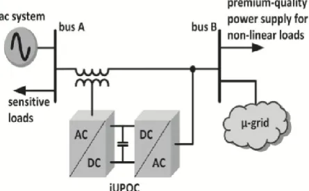
Fig. 1.Applicability of iUPQC.
II. SYSTEM MODEL
Fig. 1 depicts an electrical system with two buses in spotlight, i.e., bus A and bus B. Bus A is a critical bus of the power system that supplies sensitive loads and serves as point of coupling of a microgrid. Bus B is a bus of the microgrid, where nonlinear loads are connected, which requires premium-quality power supply. The voltages at buses A and B must be regulated, in order to properly supply the sensitive loads and the nonlinear loads. The effects caused by the
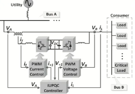
harmonic currents drawn by the nonlinear loads should be mitigated, avoiding harmonic voltage propagation to bus A.The use of a STATCOM to guarantee the voltage regulationat bus A is not enough because the harmonic currents drawn by the nonlinear loads are not mitigated. On the other hand, a UPQC or an iUPQC between bus A and bus B can compensate the harmonic currents of the nonlinear loads and compensatethe voltage at bus B, in terms of voltage harmonics, unbalance, and sag/swell. Nevertheless, this is still not enough to guarantee the voltage regulation at bus A. Hence, to achieve all the desired goals, a STATCOM at bus A and a UPQC (or an iUPQC) between buses A and B should be employed. However, the costs of this solution would be unreasonably high An attractive solution would be the use of a modified iUPQC controller to provide also reactive power support to bus A, in addition to all those functionalities of this equipment, as presented in [9] and [11]. Note that themodified iUPQC serves as an intertie between buses A and B. Moreover, the microgrid connected to the bus B could be a complex system comprising distributed generation, energy management system, and other Fig. 2. Modified iUPQC configuration.control systems involving microgrid, as well as smart grid concepts [12]. In summary, the modified iUPQC can provide the following functionalities:
a) ―smart‖ circuit breaker as an intertie between the grid andthe microgrid;
b) energy and power flow control between the grid and the microgrid (imposed by a tertiary control layer for the
microgrid);
c) reactive power support at bus A of the power system; d) voltage/frequency support at bus B of the microgrid; e) harmonic voltage and current isolation between bus A and bus B (simultaneous grid-voltage and load-current activefilteringcapability);
f) voltage and current imbalance compensation.
inside the dc link of the iUPQC balanced. In this case, the losses in the iUPQC and the active power supplied by the shunt converter must be quicklycompensated in the form of an additional active power injectedby the series converter into the bus B. The iUPQC can serve as:
a) ―smart‖ circuit breaker and as
b) power flow controller between the grid and the microgrid only if the compensating active- and reactive-power references of the series converter can be set arbitrarily. In this case, it isnecessary to provide an energy source (or large energy storage)associated to the dc link of the iUPQC.The last degree of freedom is represented by a reactive-power control variable q for the series converter of the iUPQC. Inthis way, the iUPQC will provide reactive-power compensationlike a STATCOM to the bus A of the grid. As it will be confirmed, this functionality can be added into the controller without degrading all other functionalities of the iUPQC.
Fig. 2.Proposed iUPQC configuration.
III. CONTROLLER HIERARCHY
3.1. Main Controller
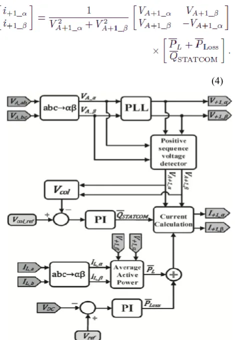
In above chapter Fig. 2 depicts the iUPQC and the measured units of a three-phase three-wire system that are used in the controller. Fig. 3 shows the proposed controller. The controller inputs are the voltages at buses A and B, the current demanded by bus B (iL), and the voltage vDC of the common dc link. The outputs are the shunt-voltage reference and the series-current reference to the pulsewidth modulation (PWM) controllers. The voltage and current PWM controllers can be as simple as those employed in [13], or be improved further to better deal with voltage and current imbalance and harmonics[15]. First, the simplified Clark transformation is applied to the measured variables. As example of this transformation, the grid voltage in the αβ-reference frame can be calculated as
(1) The shunt converter imposes the voltage at bus B. Thus, it is necessary to synthesize sinusoidal voltages with nominal amplitude and frequency. Consequently, the signals sent to the PWM controller are the phase-locked loop (PLL) outputs with amplitude equal to 1 p.u. There are many possible PLL algorithms, which could be used in this case, as verified in In the original iUPQC approach as presented in [14], the shunt-converter voltage reference can be either the PLL outputs or the fundamental positive-sequence component VA+1 of the grid voltage (bus A in Fig. 2). The use of VA+1 in the controller is useful to minimize the circulating power through the series and shunt converters, under normal operation, while the amplitude of the grid voltage is within an acceptable range of magnitude. However, this is not the case here, in the modified iUPQC controller, since now the grid voltage will be also regulated by the modified iUPQC. In other words, both buses will be regulated independently to track their reference values. The series converter synthesizes the current drawn from the grid bus (bus A). In the original approach of iUPQC, this current is calculated through the average active power required by the loads PL plus the power PLoss. The load active power can be estimated by
whereiL_α, iL_β are the load currents, and V+1_α, V+1_β are the voltage references for the shunt converter. A low-pass filter is used to obtain the average active power (PL). The losses in the power converters and the circulating power to provide energy balance inside the iUPQC are calculated indirectly from the measurement of the dc-link voltage. In other words, the power signal PLoss is determined by a proportional– integral (PI) controller (PI block in Fig. 3), by comparing the measured dc voltage VDC with its reference value.The additional control loop to provide voltage regulation like a STATCOM at the grid bus is represented by the control signal QSTATCOM in Fig. 3. This control signal is obtained through a PI controller, in which the input variable is the error between the reference value and the actual aggregate voltage of the grid bus, given by
(3) The sum of the power signals PL and PLoss composes the active-power control variable for the series converter of the iUPQC (p) described in Section II. Likewise, QSTATCOM is the reactive-power control variable q. Thus, the current references i+1α and i+1β of the series converter are
(4)
Fig. 3.Novel iUPQC controller.
3.2. Power Flow in Steady State
The following procedure, based on the average power flow, is useful for estimating the power ratings of the iUPQC Fig. 4. iUPQC power flow in steady-state. converters. For combined series–shunt power conditioners, such as the UPQC and the iUPQC, only the voltage sag/swell disturbance and the power factor (PF) compensation of the load produce a circulating average power through the power conditioners. According to Fig. 4, the compensation of a voltage sag/swell disturbance at bus B causes a positive sequence voltage at the coupling transformer (Vseries≠0), since VA ≠ VB. Moreover, Vseries and iPB in the coupling transformer leads to a circulating active power Pinner in the iUPQC. Additionally, the compensation of the load PF increases the current supplied by the shunt converter. The following analysis is valid for an iUPQC acting like a conventional UPQC or including the extra compensation like a STATCOM.
Fig. 4.iUPQC power flow in steady-state.
First, the circulating power will be calculated when the iUPQC is operating just like a conventional UPQC. Afterward, the equations will include the STATCOM functionality to the grid bus A. In both cases, it will be assumed that the iUPQC controller is able to force the shunt converter of the iUPQC to generate fundamental voltage always in phase with the grid voltage at bus A. For simplicity, the losses in the iUPQC will be neglected.
For the first case, the following average powers in steady state can be determined:
where SA and QA are the apparent and reactive power injected in the bus A; PB and QB are the active and reactive power injected in the bus B; Pshunt and Qshunt are the active and reactive power drained by the shunt converter; Pseries and Qseries are the active and reactive power supplied by the series converter, respectively. Equations (5) and (8) are derived from the constraint of keeping unitary the PF at bus A. In this case, the current passing through the series converter is responsible only for supplying the load active power, that is, it is in phase (or counter phase) with the voltages VA and VB. Thus, (7) can be stated. Consequently, the coherence of the power flow is ensured through (8). If a voltage sag or swell occurs, Pseries and Pshunt will not be zero, and thus, an inner-loop current (iinner) will appear. The series and shunt converters and the aforementioned circulating active power (Pinner) flow inside the equipment. It is convenient to define the following sag/swell factor. Considering VN as the nominal voltage
The circulating power is given by
͞Pinner=͞Pseries=͞Pshunt=3(VB-VA)(Ipb+Iinner) (12) From (11) and (12), it follows that
(13)
(14) Thus, (14) demonstrates that Pinner depends on the active power of the load and the sag/swell voltage disturbance. In order to verify the effect on the power rate of the series and shunt converters, a full load system SB=√𝑃𝑏2+ 𝑄𝑏2= 1p.u.
with PF ranging from 0 to 1 was considered. It was also considered the sag/swell voltage disturbance at bus A ranging ksag/swell from 0.5 to 1.5. In this way, the power rating of the series and shunt converters are obtained through (6)–(8) and (14). Fig. 5 depicts the apparent power of the series and shunt power converters. In these figures, the ksag/swell-axis and the PF-axis are used to evaluate the power flow in the series and shunt power converters according to the sag/swell voltage disturbance and the load power consumption, respectively. The power flow in the series converter indicates that a high power is required in case of sag voltage disturbance with high active power load consumption. In this situation, an increased Pinner arises and high rated power converters are necessary to ensure the disturbance compensation. Moreover, in case of compensating sag/swell voltage disturbance with high reactive power load consumption, only the shunt converter has high power demand, since Pinner decreases. It is important to highlight that, for each PF value, the amplitude of the apparent power is the same for capacitive or inductive loads. In other words, Fig. 5 is the same for QB capacitive or inductive. If the iUPQC performs all original UPQC functionalities together with the STATCOM functionality, the voltage at bus A is also regulated with the same phase and magnitude, that is, VA = VB = VN, and then, the positive sequence of the voltage at the coupling transformer is zero (V Series = 0). Thus, in steady state, the power flow is determined by
whereQSTATCOM is the reactive power that provides
voltage regulation at bus A. Ideally, the STATCOM functionality mitigates the inner-loop active power flow (Pinner), and the power flow in the series converter is zero. Consequently, if the series converter is properly designed along with the coupling transformer to synthesize the controlled currents I+1_α and I+1_β, as shown in Fig. 3, then a lower power converter can be employed. Contrarily, the shunt converter still has to provide the full reactive power of the load and also to drain the reactive power injected by the series converter to regulate the voltage at bus A.
3.3.Fuzzy Logic Control
L. A. Zadeh displayed the first paper on fuzzy sethypothesis in 1965. From that point forward, another dialect was produced to depict the fuzzy properties of reality, which are extremely troublesome and at some point even difficult to be portrayed utilizing traditional techniques. Fuzzy set hypothesis has been broadly utilized as a part of the control territory with some application to power framework [16]. A basic fuzzy logic control isdeveloped by a gathering of tenets in view of the humaninformation of framework conduct. Matlab/Simulink recreation model is constructed to examine the dynamic conduct of converter. Moreover, plan of fuzzy logic controller can give attractive both little flag and substantial sign element execution at same time, which is impractical with direct control method. In this way, fuzzy logic controller has been potential capacity to enhance the heartiness of compensator.
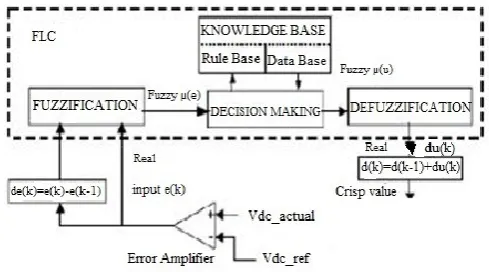
Fig 5Block diagram of the Fuzzy Logic Controller (FLC)for proposed converter
suitable etymological qualities; a learning base, which comprises of an information basewith the important semantic definitions and the controlguideline set; a choice making logic which, reenacting ahuman choice procedure, deduce the fuzzy control activity from the learning of the control rules and phonetic variable definitions; a de fuzzification interface which yields nonfuzzy control activity from a construed fuzzy control Standard Base: the components of this principle base table are resolved taking into account the hypothesis that in thetransient state, extensive blunders need coarse control,which requires coarse in-put/yield variables; in the enduring state, little mistakes require fine control, which requires fine data/yield variables. Taking into account this the components of the standard table are gotten asappeared in Table 1, with "Vdc" and 'Vdc-ref' as inputs.
Table 1: Fuzzy rules
IV. SIMULATION RESULTS
Fig 6 simulation circuit of iupqc in system
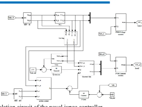
Fig 7simulation circuit of the novel iupqc controller
In the paper,In order to verify all the power quality issues described in this paper, the iUPQC was connected to a grid with a voltage sag system. In this case, the iUPQC behaves as a STATCOM, and the breaker S Sag is closed to cause the voltage sag.
Fig8 simulation circuit of the Fuzzy controller iupqc
Case 1: To verify the grid-voltage regulation (see Fig. 9), the control of the QSTATCOM variable is enabled to compose (4) at instant t = 0 s. Before the QSTATCOM variable is enabled, only the dc link and the voltage at bus B are regulated, and there is a voltage sag at bus A, as shown in Fig. 9 After t = 0s, the iUPQC starts to draw reactive current from bus A, increasing the voltage until its reference value. As shown in Fig.9, the load voltage at bus B is maintained regulated during all the time, and the grid-voltage regulation
Fig. 9 iUPQC response at no load condition: (a) grid voltages VA, (b) load voltages VB, and (c) grid currents
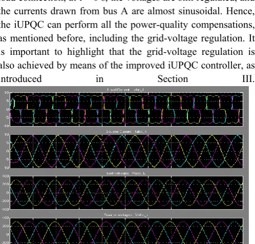
Case 2:Next, the experimental case was carried out to verify the iUPQC performance during the connection of a nonlinear load with the iUPQC already in operation. The load is a three phase diode rectifier with a series RL load at the dc link (R = 45 Ω and L = 22 mH), and the circuit breaker S Sag is permanently closed, with a LS = 10 mH. In this way, the voltage-sag disturbance is increased due to the load connection. In Fig.10, it is possible to verify that the iUPQC is able to regulate the voltages simultaneously. Even after the load connection, at t = 0 s, the voltages are still regulated, and the currents drawn from bus A are almost sinusoidal. Hence, the iUPQC can perform all the power-quality compensations, as mentioned before, including the grid-voltage regulation. It is important to highlight that the grid-voltage regulation is also achieved by means of the improved iUPQC controller, as
introduced in Section III.
Fig. 10.iUPQC transitory response during the connection of a three phase diode rectifier: (a) load currents, (b) grid currents, (c) load voltages and (d) grid voltages.Case 3:Finally, the same procedure was performed with the connection of a two-phase diode rectifier, in order to better verify the mitigation of power quality issues. The diode rectifier has the same dc load
(R = 45 Ω and L = 22 mH) and the same voltage sag (LS = 10
mH and RrmSag = 15Ω). Fig.11 depicts the transitory response of the load connection. Despite the twophase load
currents, after the load connection at t = 0 s, the three-phase current drained from the grid has a reduced unbalanced component. Likewise, the unbalance in the voltage at bus A is negligible. Unfortunately, the voltage at bus B has higher unbalance content. These components could be mitigated if the shunt compensator works as an ideal voltage source, i.e., if the filter inductor could be eliminated. In this case, the unbalanced current of the load could be supplied by the shunt converter, and the voltage at the bus B could be exactly the voltage synthesized by the shunt converter. Therefore, without filter inductor, there would be no unbalance voltage drop in it and the voltage at bus B would remain balanced. However, in a practical case, this inductor cannot be eliminated, and an improved PWM control to compensate voltage unbalances is necessary.
Fig. 11.iUPQC transitory response during the connection of a two phase diode rectifier: (a) load currents, (b) source currents, (c) load voltages, and (c) source voltages
Next, the experimental case was carried out with fuzzy controller in place of PI controller with the samecase.
Fig 13 % THD using Fuzzy logic controller
Similarly case 1 and 2 was also simulated with fuzzy logic controller and the %THD value has tabulated below
Table-1:% THD comparison table
CONCLUSION
In the improved iUPQC controller, the currents synthesized by the series converter are determined by the average active power of the load and the active power to provide the dc-link voltage regulation, together with an average reactive power to regulate the grid-bus voltage. In this manner, in addition to all the power-quality compensation features of a conventional UPQC or an iUPQC, this improved controller also mimics a STATCOM to the grid bus. This new feature enhances the applicability of the iUPQC and provides new solutions in future scenarios involving smart grids and micro grids.. Despite the addition of one more power-quality compensation feature, the grid-voltage regulation reduces the inner-loop circulating power inside the iUPQC, which would allow lower power rating for the series converter. The grid-voltage regulation was achieved with no load, as well as when supplying a three-phase and two-phase nonlinear load. Simulation results and comparison table of % THDhave verified a suitable performance of voltage regulation at both sides of the iUPQC, and Fuzzy logic controller is better than PI in compensating harmonic current and voltage imbalances .
REFERENCES