A Novel Wideband Circularly Polarized Patch Array
with Meta-Surface
Rui-Qi Wang*, Yong-Chang Jiao, Liang Lu, and Huan Zhang
Abstract—A wideband sequential-phase-feeding circularly polarized (CP) patch array is proposed in this paper. A well-designed meta-surface is placed above the array to enhance its impedance and axial ratio (AR) bandwidths. The proposed patch array has an overall size of 1.275λo×1.275λo×0.0935λo at 5.1 GHz. Measured results show that the impedance bandwidth (|S11|<−10 dB) of the array is 24.26%
from 4.74 GHz to 6.05 GHz, and its 3 dB axial ratio bandwidth is 19% from 4.75 GHz to 5.75 GHz. The measured gain of the array at 5.7 GHz is 10.8 dBic. The measured results agree well with the simulated ones.
1. INTRODUCTION
With the rapid development of modern wireless communication systems, circularly polarized (CP) antennas [1–4] are attracting more and more attention because they provide flexibility in the orientation angle between the transmitter and the receiver. A 2×2-element planar array with sequential-phase feeding can generate circularly polarized characteristics. Various structures of the sequential-phase feeding networks have been proposed in [5–8]. These sequential-phase feeding networks with phases of 0◦, 90◦, 180◦, and 270◦ at four ports have been extensively used to improve the impedance and axial ratio (AR) bandwidths in the 2×2-element array design. Various antenna arrays are designed with sequentially rotated technique in [9–15]. In [9], a 2×2-element circularly polarized microstrip antenna array with the sequential-phase feeding network operating in Ka band was proposed. Lin and Lin investigated uniform transmission lines to obtain a circularly polarized sequential-rotation array [10]. The 2×2-element single-layer patch arrays in [9] and [10] have a narrow CP bandwidth, which are limited by the feeding network and radiating elements.
In recent years, metamaterials have been widely studied, and various CP antennas loaded with the meta-surface structures were proposed for the size miniaturization, the radiation pattern improvement as well as the polarization agility [16–20]. As a sub-field of metamaterials, the meta-surface structures, such as the mushroom-like structure [17], the reactive impedance surface (RIS) [18] and the artificial magnetic surface (AMS) [19], have also attracted increasing attention. In [20], the corner-cut artificial magnetic conductor (AMC) structure is used as the antenna ground plane replacing the conventional ground plane to effectively realize a better performance such as axial ratio bandwidth and radiation gain according to the compared results.
Based on the antenna array in [8] and the corner-cut AMC structure in [20], a novel circularly polarized patch array with meta-surface is presented. The array consists of four rectangle patches, and each rectangle patch is truncated by two isosceles triangles in a diagonal direction. A crossed slot is etched in the center of each rectangular patch to improve the impedance bandwidth, and a meta-surface is placed above the array to enhance the axial ratio bandwidth. Due to the advantages of wide band, light weight and ease of fabrication, the proposed antenna has wide and potential applications for
Received 14 May 2016, Accepted 7 July 2016, Scheduled 19 August 2016
* Corresponding author: Rui-Qi Wang ([email protected]).
2 Wang et al.
wireless communications such as WLAN/WiMAX. Compared with the antenna in [8], which is similar to the proposed antenna, the proposed antenna has experimentally wider impedance and axial ratio bandwidths.
2. ANTENNA DESIGN AND CONFIGURATION
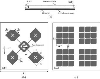
Geometry of the proposed CP antenna with meta-surface is shown in Figure 1. The overall antenna has a two-dielectric layered structure with lower substrate (Sub1) and upper substrate (Sub2). Figure 1(a) shows the cross-sectional view of the proposed antenna. The thicknesses of these two substrates are 1.5 mm and 1 mm, with 4 mm air-gap between them.
As shown in Figure 1(b), Sub1 has a relative permittivity of 2.65 and loss tangent of 0.02. The 2×2-element patch array and ground plane are printed on the top and bottom layers, respectively. Both the substrate and the ground are squares with side length L. Four identical rectangle patches with dimensions of l1 ×l2 are arranged in a sequentially rotated structure. Each rectangle patch is
truncated by two isosceles triangles in a diagonal direction. A pair of crossed slots is also added in the central part of each patch. As shown in Figure 1(b), b1 is the vertical length of the truncated isosceles
triangle, S1 and S2 are lengths of two orthogonal slots in each patch. The feeding network is located
at the central part of the array, which consists of a square loop and an annular-sector of 270◦. The square loop and the annular-sector are connected via two strips, andlr is the distance from the feeding point at one strip to center of another strip. The feeding network is connected to four rectangle patch elements via four strips with current phases of 0◦, 90◦, 180◦, and 270◦ at four ends.
The relative permittivity and loss tangent of Sub2 are 2.55 and 0.02, respectively. Figure 1(c) shows the meta-surface structure etched on the top layer of Sub2, which is formed by two-dimensional periodic metal cells, similar to the AMC structure design in [20]. Four groups of 3×3 unit-cells are arranged just above four patch elements with gap g between two adjacent cells, and each group has the same orientations. The unit-cell of the meta-surface is a square patch truncated by two isosceles triangles in
(a)
(b) (c)
Figure 1. Geometry of the proposed antenna. (a) Side view, (b) top view of Sub1, and (c) top view of Sub2. (Parameters: H = 4 mm, L = 75 mm, l1 = 16.5 mm, l2 = 16 mm, lr = 3 mm, b1 = 4.2 mm,
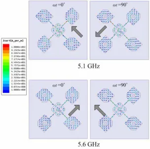
Figure 2. Current distributions on the patch array at 5.1 GHz and 5.6 GHz with different phases.
a diagonal direction. This structure is designed to have a phase difference of approximately 90◦ between the X- and Y-polarized components in the far field radiation at a frequency of about 5.4 GHz. After the wave across the structure, two orthogonal components of equal amplitude but with a 90◦ phase difference between them are obtained so as the antenna can radiate circular polarization at around 5.4 GHz with a low AR. As shown in Figure 1(c), ais the side length of the square patch, andb2 is the
vertical length of the truncated isosceles triangle. To guarantee a fair comparison, dimensions of meta-surfaces are optimized to constitute the proposed antenna with dimensions of Sub1 keeps unchanged. Its parameters are given in Figure 1.
By carefully optimizing the central sequential-phase feeding network and each corner-cut patch with crossed slots simultaneously, two narrow AR bandwidths of 4.94–5.05 GHz and 5.66–5.75 GHz are obtained. Then, four groups of 3×3 unit-cells are arranged just above four patch elements to excite CP waves in the middle frequency. With the loading of well-designed meta-surface, the antenna can not only excite a CP wave in the frequency band around 5.4 GHz, but also provide good input impedance matching for enhancing the impedance bandwidth of the antenna (compared in Figure 5). Moreover, a gain enhancement of 1 dBic at 5.4 GHz is obtained. To understand of CP radiation generation of the proposed antenna, simulated surface current distributions on the top layer of Sub1 at 5.1 GHz and 5.6 GHz with different time phases (ωt) are shown in Figure 2. The simulated results are obtained by using ANSYS HFSS version 15. At these two frequencies, all the four elements are exited at the same time with consistent current directions at ωt= 0◦, and the current directions rotate 90◦ at ωt= 90◦. It can be observed that both the array and the elements generate circular polarization in these two frequencies.
3. RESULTS AND DISCUSSION
4 Wang et al.
Figure 3. Photographs of the fabricated antenna. (Sub1, Sub2, and side view).
(a) (b)
Figure 4. |S11|’s, ARs and gains of the antenna for different values ofH.
radiation characteristics. Photograph of the fabricated antenna is shown in Figure 3. Four plastic screws are installed in the corners of the substrates.
The reflection phase characteristics of meta-surface structure are affected by the gap H between Sub1 and Sub2. By adjusting gapHbetween Sub1 and Sub2, a wide CP operating band can be obtained. For different values of gap H,|S11|’s and ARs of the proposed antenna are shown in Figure 4(a) while
gains are shown in Figure 4(b). It is apparent that the antenna exhibit two resonance frequencies in the |S11| profile. When gap H increases from 3 mm to 5 mm, the second resonance frequency shifts
toward the lower band. In the AR profile, the AR bandwidth is improved as H increases, and the resonance frequencies are shifted toward the higher band. It is also found that a higher gain is obtained when H = 4 mm in Figure 4(b). Therefore, H is chosen as 4 mm, and two orthogonal waves with a phase difference of approximately 90◦ in the far field are obtained to generate circularly polarized characteristics covering the frequency band of 4.64 to 5.8 GHz.
The original design, namely Sub1 shown in Figure 1, is simulated and optimized firstly, and its results are given as references. Then, meta-surfaces are suspended above Sub1 to constitute the proposed antenna with dimensions of Sub1 keeping unchanged to guarantee a fair comparison. Vector network analyzer ANRITSU MS46322A was used to measure the S11 parameter while radiation patterns were
achieved in anechoic chamber (shown in Figure 6). The simulated and measured |S11| results of the
proposed antenna are shown in Figure 5(a), while its simulated and measured AR results are presented in Figure 5(b). The simulated impedance bandwidth of the proposed antenna for |S11| < −10 dB is
(a) (b)
Figure 5. Simulated and measured (a)|S11|’s and (b) ARs.
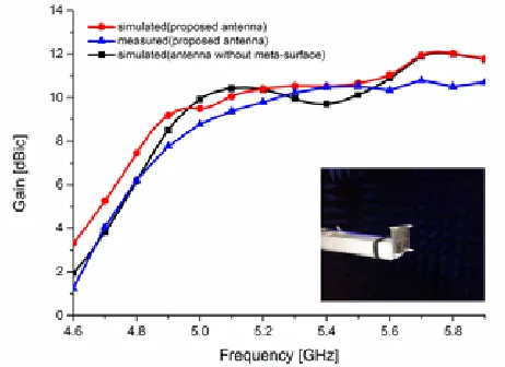
Figure 6. Simulated and measured gains.
for comparison. Results show that the antenna without meta-surface obtains an impedance bandwidths (|S11|<−10 dB) of 11.56% (4.81–5.4 GHz) and 5.93% (5.56–5.9 GHz), the 3 dB axial ratio bandwidths
of 2.2% (4.94–5.05 GHz) and 1.58% (5.66–5.75 GHz) at the lower and upper bands, respectively. Thus, it is clearly seen that the impedance and AR bandwidths are improved effectively by utilizing the meta-surface. In the AR profile, the antenna exhibits three resonances. The lowest and highest CP resonances are generated by the patch array, and the middle one is generated by the meta-surface.
The simulated and measured gains are shown in Figure 6. The simulated peak gain across the AR bandwidth is about 12.18 dBic at 5.7 GHz, while the measured peak gain is 10.8 dBic at 5.7 GHz. We can also observe that the gains become smooth within the AR bandwidth, compared with the gains of the antenna without meta-surface.
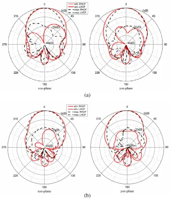
The simulated and measured normalized radiation patterns in xoz- and yoz-planes at different frequencies are shown in Figure 7. The measured results agree well with the simulated ones. The measured co-polarization (right-hand circular polarization, RHCP) gain is 16 dB higher than the cross-polarization (left-hand circular cross-polarization, LHCP) gain within the bandwidth in both planes. The difference between simulated and measured results may be caused by the measurement errors and inaccuracies in the fabrication process.
6 Wang et al.
(a)
(b)
Figure 7. Simulated and measured radiation patterns in xoz-plane andyoz-plane at (a) 5.1 GHz and (b) 5.6 GHz.
Table 1. Comparison of the proposed array with other 2×2 arrays.
Ref. BW (freq.
range) (GHz)
ARBW (freq.
range) (GHz) Peak gain Antenna size (mm
3)
[11] 1.7 (4.5–6.2) 1.47 (4.75–6.22) 7.2 dBic (5.5 GHz) ∼
[12] 2.73 (4.45–7.84) 3.02 (4.41–7.43) 14.8 dBic 1.56λ0×1.34λ0×0.22λ0 at 5.5 GHz
[13] 2.8 (4–6.8) 1.9 (5.1–7) 7.46 dBic (5.73 GHz) 1.69λ0×1.69λ0×0.015λ0 at 5.5 GHz
[14] 4.4 (3.4–7.8) 2 (4.6–6.6) 14.8 dBic (6.5 GHz) 2.24λ0×1.94λ0×0.016λ0 at 6 GHz
[8] 1.03 (5.2–6.23) 0.7 (5.25–5.95) 12 dBic (5.75 GHz) 1.372λ0×1.375λ0×0.0275λ0 at 5.5 GHz
along with other parameters. It shows an increased impedance and axial ratio bandwidths compared with [8] while a significant size reduction is proposed compared with the antenna proposed in [14]. Moreover, the gain is comparable to previous designs. Thus, the proposed antenna exhibits a good performance based on a tradeoff between several characteristics such as CP bandwidth and realized gain.
4. CONCLUSIONS
In this paper, a 2×2-element circularly polarized patch array with meta-surface is proposed for improving bandwidth. By using a sequential-phase feeding network, four patch elements are exited with sequential phases of 0◦, 90◦, 180◦, and 270◦. With the well-designed meta-surface placed above the array, a wideband operation can be obtained. Measured results show that the impedance bandwidth of the array is 24.26% from 4.74 GHz to 6.05 GHz, and its 3 dB axial ratio bandwidth is 19% from 4.75 GHz to 5.75 GHz. The peak gain is 10.8 dBic at 5.7 GHz. The measured results agree well with the simulated ones.
REFERENCES
1. Yang, S. S., K.-F. Lee, A. A. Kishk, and K.-M. Luk, “Design and study of wideband single feed circularly polarized microstrip antennas,” Progress In Electromagnetics Research, Vol. 80, 45–61, 2008.
2. Mohammadi, P. and V. Rafii, “High gain and broadband circularly polarized square slot antenna array,” Progress In Electromagnetics Research Letters, Vol. 43, 105–113, 2013.
3. Fan, F., W. Wang, Z.-H. Yan, and K.-B. Tan, “Circularly polarized SIW antenna array based on sequential rotation feeding,” Progress In Electromagnetics Research C, Vol. 47, 47–53, 2014. 4. Xu, P., Z.-H. Yan, T.-L. Zhang, and X.-Q. Yang, “Broadband circularly polarized slot antenna array
with Fan-shaped feed line and L-shaped grounded strips,” Progress In Electromagnetics Research Letters, Vol. 44, 125–131, 2014.
5. Ramirez, R. R., F. D. Flaviis, and N. G. Alexopoulos, “Single-feed circularly polarized microstrip ring antenna and arrays,” IEEE Trans. Antennas Propag., Vol. 48, No. 2, 1040–1047, 2000. 6. Lo, W. K., C. H. Chan, and K. M. Luk, “Circularly polarised patch antenna array using
proximity-coupled L-strip line feed,” Electron. Lett., Vol. 36, No. 14, 1174–1175, 2000.
7. Lu, K. H. and T. N. Chang, “Circularly polarized array antenna with corporate-feed network and series-feed elements,”IEEE Trans. Antennas Propag., Vol. 53, No. 10, 3288–3292, 2005.
8. Deng, C., Y. Li, Z. Zhang, and Z. Feng, “A wideband sequential-phase fed circularly polarized patch array,”IEEE Trans. Antennas Propag., Vol. 62, No. 7, 3890–3893, 2014.
9. Chen, A., Y. Zhang, Z. Chen, and S. Cao, “A Ka-band high-gain circularly polarized microstrip antenna array,”IEEE Antennas Wireless Propag. Lett., Vol. 9, 1115–1118, 2010.
10. Lin, S.-K. and Y. Lin, “A compact sequential-phase feed using uniform transmission lines for circularly polarized sequential-rotation arrays,” IEEE Trans. Antennas Propag., Vol. 59, No. 7, 2721–2724, 2011.
11. Karamzadeh, S., B. Virdee, V. Rafii, and M. Kartal, “Circularly polarized slot antenna array with sequentially rotated feed network for broadband application,” International Journal of RF and microwave Computer, Vol. 25, No. 4, 358–363, 2015.
12. Karamzadeh, S., V. Rafii, H. Saygin, and M. Kartal, “Polarisation diversity cavity back reconfigurable array antenna for C-band application,” IET Microwaves, Antennas & Propagation, Vol. 10, No. 9, 955–960, 2016.
8 Wang et al.
14. Karamzadeh, S., V. Rafii, M. Kartal, O. N. Ucan, and B. S. Virdee, “Circularly polarised array antenna with cascade feed network for broadband application in C-band,”Electron. Lett., Vol. 50, No. 17, 1184–1186, 2014
15. Maddio, S., “A circularly polarized antenna array with a convenient bandwidth/size ratio based on non-identical disc elements,” Progress In Electromagnetics Research Letters, Vol. 57, 47–54, 2015. 16. Li, K., L. Li, and Y. Cai, “A novel design of low-profile dual-band circularly polarized antenna
with meta-surface,” IEEE Antennas Wireless Propag. Lett., Vol. 14, 1650–1653, 2015.
17. Wu, J., Z. Wang, X. Liu, and Y. Yin, “Low-profile broadband circularly-polarized antennas with metamaterial structures,”Microw. Opt. Technol. Lett., Vol. 57, No. 7, 1565–1568, 2015.
18. Agarwal, K., Nasimuddin, and A. Alphones, “Compact asymmetric-slotted-slit patch based circularly-polarized antenna with reactive impedance surface substrate,” Microw. Opt. Technol. Lett., Vol. 54, No. 11, 2505–2510, 2012.
19. Yang, W., K. Tam, and W. Choi, “Novel polarization rotation technique based on an artificial magnetic conductor and its application in a low-profile circular polarization antenna,”IEEE Trans. Antennas Propag., Vol. 62, No. 12, 6206–6216, 2014.