Available Online at www.ijcsmc.com
International Journal of Computer Science and Mobile Computing
A Monthly Journal of Computer Science and Information Technology
ISSN 2320–088X
IJCSMC, Vol. 4, Issue. 1, January 2015, pg.128 – 133
REVIEW ARTICLE
Review of Microstrip Patch Antenna Using UWB
for Wireless Communication Devices
Nita Kalambe, Prof. Dhruv Thakur, Prof. Shubhankar Paul
Department of Electronics & Telecommunication Engineering, Bansal Institute of Science and Technology, Bhopal
Abstract— As per Microstrip Patch antenna (MPA) provide low profile and low volume, so it is use in a now a
days communication devices. In this paper study of past few year shows that most of labour on MPA is targeted on
planning compact sized microstrip antenna. A novel ultra-wideband printed monopole antenna can be used in
wireless communication devices. In this speedy dynamical world in wireless communication dual or multiband
antenna has been playing a key role for wireless service needs application. In this paper, we study microstrip
patch antenna design with form of substrate, feed techniques and slots for UWB based system applications.
Index Terms— Microstrip patch antenna, Ultra Wide band, Operating frequency, feeding techniques
I: INTRODUCTION
An antenna both transmitting and receiving the information so it is the essential part of the microwave communication. It is a device that is made to efficiently radiate and receive the radiated electromagnetic waves. Antenna is a transducer which converts the voltage and current on a transmission line into an electromagnetic field in a space, consisting of an electric and magnetic field travelling right angles at each other [1,2,3].
Generally, to detect the cancerous tissue, the microwave imaging system is made by a circular cylindrical array antenna microwave imaging systems need little antennas with omni-directional radiation patterns and enormous information measure. Thus, in microwave imaging systems, over the full operative band one of key issues is that the style of a compact antenna whereas providing wideband characteristic. It is a well-known incontrovertible fact that placoid monopole antennas physical options, like easy structure, little size and low price present very appealing [2-4]. Consequently, variety of planner monopoles with totally different geometrics are through an automatic style strategies and experiment characterized have been developed to attain the optimum placoid form [5].With the event of band wireless communication systems, ultra wide band (UWB) systems have been increasing quickly. The Federal communications Commission allotted the wave band 3.1~10.6 GHz for the UWB services. These UWB systems have been used for radiolocation applications, localization, information communications etc. The antennas of UWB systems area unit embedded into these transmission devices, the house networking system is wide utilized in transmission devices like HDTV’s, DVD’s, cameras and private computers through the UWB service channels [6].
The most commonly employed microstrip patch antenna is a rectangular patch. The rectangular patch antenna is approximately a one wavelength long section of rectangular microstrip transmission line. The antenna is loaded with a dielectric as its substrate, the length of the antenna decreases as the relative dielectric constant of the substrate increases . When the air is the antenna substrate the length of the rectangular microstrip antenna is approximately one half of a free space wavelength. The proper miniaturized antenna will improve the transmission and reception.
happens once the dipole or patch dimensions are of a half guided wavelength. Longitudinal current distribution here for their pattern and gain are similar, however the alternative properties (e.g. input electrical phenomenon and polarization) will vary. When the signal frequency is within the section of a resonance, a microstrip resonator radiate comparatively broad beam, broadside to the plane of the substrate. A serious a part of the sign participates in radiation and so the resonator acts
as an antenna. Since patch dimensions should be of the order of a radio-controlled wavelength, its directivity is extremely low as an example, a half-wavelength dipole generally features a gain of regarding 5-6 Db and beam width between 70 and 90 degrees.
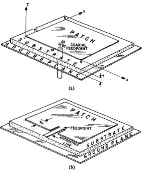
The design of a microstrip antenna begins by deciding used for the antenna so the size of the patch. due to the fringing fields on the radiating edges of the antenna there's a line extension related to the patch. The basic structure of the microstrip patch antenna design is shown in fig.1.
Fig. 1 The structure of microstrip antenna.
II: LITERATURE REVIEW
The construct of microstrip antenna with conducting patch on a ground plane separated by insulator substrate was undeveloped till the revolution in electronic circuit shrinking and large-scale integration in 1970. After that several mortal have drawn the radiation from very cheap plane by a insulator substrate for numerous configurations. Various mathematical analysis models were developed for this antenna and its applications were extended to several numerous fields. The little strip antennas unit today antenna designer’s selection. Throughout this section, the microstrip antenna literature survey is mentioned.
“Nasser Ojaroudi” has proposed a compact with multi-resonance characteristics UWB/Omni-Directional Microstrip Monopole Antenna with multi-resonance characteristic has been projected for microwave imaging systems leads to compact antenna with smart omni-directional radiation characteristics for projected in operating frequencies. The fictious antenna satisfies the VSWR<2 demand from 2.95 to 14.27 GHz so as to reinforce information measure frequency, two pairs of formed slits and parasitic structures in the ground plane area unit used and therefore abundant wider electrical phenomenon with an ordinary square radiating patch and small size of 12×18mm2[1,2,5,7,8].
“T. Suganthi” has researched that, the size of the antenna is obtained through parametric analysis. As the designed antenna meeting the requirements of GSM application, it could be highly useful for mobile application. In this paper, design and Analysis of Microstrip Patch. An antenna for GSM application is presented by. Antenna parameters such as Return Loss, VSWR of the designed antennas are -29.21dB, 1.0717 respectively [3, 10].
“Ramna” has proposed Design Of Rectangular Microstrip
position at center frequency of 1.95 GHz using Sonnet13.52,PSO has been used. Microstrip patch antenna resonated at exact 1.95GHz.PSO
saves time as compared to the design of patch antenna without optimization algorithm and also PSO restricts the variation from center frequency [4,6].
“Jyoti Ranjan Panda” has researched that A Compact Printed Monopole Antenna(PMA) for Dual-band RFID and WLAN Applications. From 9-shaped folded antenna, dual-band operation is achieved which is printed on a non-conductor backed dielectric. Impedance bandwidth 33.13% at 2.43 GHz and 36.43% at 2.43GHz is measured of the PMA. The proposed antenna exhibits broadband impedance matching, consistent omni directional radiation patterns and appropriate gain characteristics (>2.5 dBi) in the RFID and WLAN frequency regions [11].
“Mohammad Ojaroudi” has presented a novel, compact printed monopole antenna (PMA) for UWB applications. The fabricated antenna satisfies the 10-dB return loss requirement from 3.12 to 12.73 GHz. The feed-gap distance, the sizes of T-shaped notch, and the sizes of two rectangular slots in the antenna’s patch is used to obtain the wide bandwidth have been optimized by parametric analysis. This antenna exhibits good radiation behavior within the UWB
frequency range. [12].
“ Y. Chen”, has proposed Design And Analysis Of Wideband Planar Monopole Antennas Using The Multilevel Fast Multipole Algorithm. In this to analyze the impedance bandwidth and radiation performance of the monopoles a full-wave method of moment (MoM) based on the electric field integral equation (EFIE) is applied. Meanwhile, to reduce the memory requirements and computational time, the multilevel fast multipole algorithm (MLFMA) is employed. Two wideband planar monopoles attached to finite sized ground planes are designed, analyzed, and fabricated. Both of the simulated and measured results shows that the two monopoles are capable to cover the AMPS, GSM900, and DCS band. In the whole operating frequency, both of the monopoles can provide a nearly omni-directional radiation pattern in the azimuth plane [13].
“Nakchung Choi” has proposed a notch-frequency band for a UWB antenna which can be embedded into laptop computers with an I-shaped parasitic element. This novel band-notched UWB antenna has the capability to provide easy tuning of the notch-frequency function and bandwidth with good stop band rejection [14,15, 16].
III: Study of Antenna Designing Parameters
There are three essential parameters for design of a rectangular microstrip Patch Antenna. Firstly, the resonant frequency (f0 )
of the antenna must be selected appropriately. The frequency range for ultra wide band applications is 3.1 to 10.6 GHz and the design antenna must be able to operate within this frequency range.
The second important parameter of antenna is substrate thickness. The height of dielectric substrate (h) of the microstrip patch antenna with coaxial feed is to be used in S-band range frequencies. Hence, the height of dielectric substrate employed in this design of antenna is h= 1.6mm
The third important parameter of good antenna design is dielectric substrate (ℇr). A thick dielectric substrate having low
dielectric constant is desirable. This provides better efficiency, larger bandwidth and better radiation. The low value of dielectric constant increases the fringing field at the patch periphery and thus increases the radiated power lower quality factor Q. FR-4 Epoxy which has a dielectric constant of 4.4 and loss tangent equal to 0.02 can be used for new antenna design.
The look of patch are going to be fed by a microstrip transmission line
.
Patch is act as a conductor. This structure of the antenna having length of patch L, width W ,height of dielectric substrate h and Loss tangent. The dielectric constant of the substrate material is an important design parameter. These are placed on infinite ground plane.The length is formed around
L
g/2, that the patch starts to radiate, that typically incorporates 50 Ohm impedance. Theantenna is typically fed at the diverging edge on the dimension W because it offers sensible
polarization , but the disadvantages area unit the spurious radiation and want for electric impedance matching this is often as a result of 150 to 300typical edge resistance of a microstrip antenna ranges.
The antenna parameters antenna can be calculated by the transmission line method [Balanis, 2005] and [4] as exemplified below
:
Width of the Patch:
W =
√ ℇ
The width of the antenna can be determined by (James et al, 1989):
where, c = speed of light in free-space.
Resonant Frequency:
f
0 √ℇand length Le (Effective Length) is chosen as
L
e = L+2ΔLThe actual length L of the patch is given as (Pozar et al, 1995):
Formula for the extended length due to fringing effect is given as,
=
0.412
(
ℇℇ
)
ℇ
effℇ ℇ
(
)
Where, h = Height of dielectric substrate W = Width of the patch
Ground Dimension
For practical considerations, it is essential to have a finite ground plane if the size of the ground plane is greater than the patch dimensions by approximately six times the substrate thickness all around the periphery. Hence, the ground plane dimensions would be given as (Huang, 1983) (Thomas, 2005):
L
g= 6h+L
W
g= 6h+W
By using these formulas we can calculate L*W the dimension of the main patch and Lg*Wg the dimension of the ground plane of
the main patch.
Feed Location Design:
IV: Results and Analysis
Result and analysis of previous literature papers is given in literature review table given in below
Literature Review Table:
Ref
No.
Approach
Conclusion
1
Modified ground plane with pairs of L-shaped slits and parasitic structuresBandwidth of more than 130% (2.95-14.27 GHz)
radiation
efficiency is greater
than 86%
3
VSWR and Radiation PatternReturn loss of -29.2133 dB at 1.8 GHz
5
Inverted U-shaped slots and two L-shaped parasitic elements
Bandwidth of more than 130% (2.9-14.3 GHz) & good omni-directional radiation pattern
8
I-shaped slot on the feed-line and a pair of S-shaped slots in the ground plane
Wider impedance bandwidth & radiation efficiency is greater than 82%
12
Ground plane with inverted T-shaped notch
Bandwidth of more than 120% (3.12– 12.73 GHz)
14
Half-wavelength parasitic element printed on the rear side of the substrate.
Impedance bandwidth of antenna is 3.1-11.4 GHz (114%)
15
Two monopoles of the same size and
a small strip bar
Band notch mechanism of the antenna was examined with current distribution
16
Embedding a notch in the ground plane
Frequency band of 2.95 to 11.7 GHz with the stop band of 4.92 - 5.86 GHz.
V: Conclusion
References:
[1] : Nasser Ojaroudi*, Mohammad Ojaroudi, and Yaser Ebazadeh “UWB/Omni-Directional Microstrip Monopole Antenna for Microwave Imaging Applications “.Progress In Electromagnetics Research C, Vol. 47, 139- 146, 2014.
[2] : A.Kasinathan, Dr.V.Jayaraj,M.Pachiyaannan,” E-Shape Microstrip Patch Antenna Design for Wireless Applications” IJISET - International Journal of Innovative Science, Engineering & Technology, Vol. 1 Issue 3, May 2014.
[3] : T.Suganthi1, Dr.S.Robinson2, G.Kanimolhi3, T.Nagamoorthy4” Design and Analysis of Rectangular Microstrip Patch Antenna for GSM Application” IJISET - International Journal of Innovative Science, Engineering & Technology, Vol. 1 Issue 2, April 2014.
[4] : Darshana R. Suryawanshi, Prof. Bharati A. Singh,A Compact Rectangular Monopole Antenna with Enhanced Bandwidth, IOSR Journal of Electronics and Communication Engineering (IOSR-JECE), Volume 9, Issue 2, Ver. VII (Mar - Apr. 2014), PP 54-57.
[5] : Reza Jafarlou, Changiz Ghobadi, Javad Nourinia “Design, Simulation, and Fabrication of an Ultra-Wideband Monopole Antenna for Use in Circular Cylindrical Microwave Imaging Systems “Australian Journal of Basic and Applied Sciences, 7(2): 674-680, 2013 ISSN 1991-8178.
[6] : Ramna1,Amandeep Singh Sappal,” Design Of Rectangular Microstrip Patch Antenna Using Particle Swarm Optimization” International Journal of Advanced Research in Computer and Communication Engineerin Vol. 2, Issue 7, July 2013.
[7] : W. Mazhar, M. A. Tarar, F. A. Tahir, Shan Ullah, and F. A. Bhatti “Compact Microstrip Patch Antenna for Ultra-wideband Applications” PIERS Proceedings, Stockholm, Sweden, Aug. 12{15, 2013.
[8] : N. Ojaroudi, M. Ojaroudi, F. Geran, and Sh. Amiri “Omni-Directional/Multi-Resonance Monopole Antenna for Microwave Imaging Systems”. 20th
Telecommunications forum TELFOR 978-1-4673-2984- 2012 IEEE.
[9] : Jawad K. Ali, Mahmood T. Yassen, Mohammed R. Hussan, and Mohammed F. Hasan” A New Compact Ultra Wideband Printed Monopole Antenna with Reduced Ground Plane and Band Notch Characterization” Progress In Electromagnetics Research Symposium Proceedings, KL, MALAYSIA, March 27–30, 2012 1531.
[10] : S. M. Naveen, R. M. Vani, P. V. Hunagund,“Compact Wideband Rectangular Monopole Antenna for Wireless Applications1” Wireless
Engineering and Technology, 2012, 3, 240-243.
[11] : Jyoti Ranjan PANDA, Aditya Sri Ram SALADI, Rakhesh Singh KSHETRIMAYUM,” A Compact Printed Monopole Antenna for Dual-band RFID and WLAN Applications” RADIOENGINEERING, VOL. 20, NO. 2, JUNE 2011.
[12] : Mohammad Ojaroudi, Changiz Ghobadi, and Javad Nourinia “Small Square Monopole Antenna With Inverted T-Shaped Notch in the Ground Plane for UWB Application” IEEE ANTENNAS AND WIRELESS PROPAGATION LETTERS, VOL. 8, 2009.
[13] : Y. Chen, S. Yang, S. He, and Z. Nie, Design And Analysis Of Wideband Planar Monopole Antennas Using The Multilevel Fast Multipole Algorithm, Progress In Electromagnetics Research B, Vol. 15, 95-112, 2009.
[14] : Nakchung Choi, Changwon Jung, Joonho Byun, Frances J. Harackiewicz, Senior Member, IEEE, Myun-Joo Park,Yong-Seek Chung, Taekyun Kim, and Byungje Lee, Member, IEEE “Compact UWB Antenna With I-Shaped Band-Notch Parasitic Element for Laptop Applications” IEEE ANTENNAS And WIRELESS PROPAGATION LETTERS, VOL. 8, 2009.
[15] : K. Chung, S. Hong and J. Choi,” Ultrawide-band printed monopole antenna with band-notch filter” IET Microw. Antennas Propag., Vol. 1, No. 2 April 2007.
[16] : Wooyoung Choi*, Jihak Jung, Kyungho Chung, Jaehoon Choi**” Compact Wideband Printed Monopole Antenna with Frequency Band-stop Characteristic” 0-7803-8883-6/05/$20.00 ©2005 IEEE.