A Novel Compact CRLH Bandpass Filter on CSRR-Loaded
Substrate Integrated Waveguide Cavity
Bo Yin1, 2, Zhangyao Lin1, *, Xu Cai1, Honggang Hao1, 2, Wei Luo1, 2, and Wen Huang1, 2
Abstract—A compact composite right/left-handed (CRLH) bandpass filter with wide out-of-band rejection, which utilizes a substrate integrated waveguide (SIW) and modified complementary split-ring resonators (CSRRs) is presented. By incorporating two sets of CSRRs resonators (the top and bottom CSRRs) into SIW cavity, the proposed filter obtains a high selectivity. Besides, the filter has the CRLH property, and no additional areas are required because of the structure of the top CSRRs and the gap between them. At the same time, two slots of etched units used in feeding lines are replaced to obtain a wide out-of-band rejection. Finally, the measured results show that the filter has a wide stopband with rejection over 20 dB up to 4.3 times of the center frequency, implying that the experimental results are in good agreement with simulated ones.
1. INTRODUCTION
With the rapid development of information technology, communication systems have higher requirements for filter performance, especially in aspects of small size, high selectivity and wideband out of band suppression.
Various techniques have been investigated to achieve high performances of filters, such as compactness, high selectivity and wide stopband [1–3]. Broadband performance of a filter is achieved through multimode resonators, and an electromagnetic bandgap (EBG) structure with slow-wave characteristics is adopted to improve the upper stopband [1]. Substrate integrated waveguide (SIW) has attracted much attention in both industry and academia due to the advantages of higher quality factor (Q), more compact size and lower cost compared with microstrip technology in the millimetre wave band. In order to improve out-of-band rejection and sharpen skirt selectivity, 1/4 open circuit lines at the input and output ports of the SIW filter are introduced [2]. Application of slow wave technique as a miniaturizing technique is found in [3], and the slow wave phenomena of two SIW bandpass filters are realized through using inductive post and iris.
As a metamaterial structure, complementary split-ring resonators (CSSRs) can provide a negative effective permittivity in the vicinity of resonant frequency, which is combined with the gaps between the top of CSRRs, producing negative permeability to construct the CRLH filters. CSSRs have been loaded into SIW which generates a passband below the waveguide cutoff frequency and inhibits signal transmission of off-band. With the integration of CSRRs to SIW, various high performance filters have been designed. In [4], the proposed filter is implemented by a resonant mode of CSRRs and two degenerate modes of an SIW rectangular resonator, and its passband could be changed through the dimensions of CSRRs. In [5, 6], high selectivity of the filter can be achieved by embedding CSRRs into an SIW. In [7], a novel dual-band SIW bandpass filter (BPF) based on CSRRs is proposed. Two CSRRs are etched on the top layer coupled with TE102 and TE201 modes of the cavity, respectively
Received 26 September 2018, Accepted 23 October 2018, Scheduled 5 November 2018 * Corresponding author: Zhangyao Lin ([email protected]).
which construct the dual-frequency passbands. An ultra-wideband SIW filter is illustrated in [8] by SIW-coupled CSRR pair. In [9] and [10], CSRRs loaded in a double-sided half mode substrate integrated waveguide (HMSIW) are presented to achieve more compact size. In [11], a horizontal-asymmetrical SICSRR is developed and loaded into HMSIW to constitute a resonant unit cell, which can operate at a lower frequency than that of the conventional HMSIW-CSRR resonator because they occupy the same physical circuitry size. In [12], a unique structure for dual and quadruple passband filters based on a circular cavity SIW loaded with semicircular CSRRs is presented, which generates a passband below the waveguide cutoff frequency.
In this paper, the top CSRRs of SIW cavity are used as a resonator to work together with the cavity for constituting a CRLH filter. Due to CSRRs left-handed nature, it is easier to form a stopband for the filter, which offers better out-of-band rejection and achieves miniaturization. A wide out-of-band suppression is obtained by etching slots on two feeding lines. Several BPFs with CRLH features presenting wide out-of-band rejection and centered at 5G band are designed and implemented, demonstrating the aforementioned good features.
2. ANALYSIS AND DESIGN
2.1. CRLH-SIW Filters
SIW has similar characteristics to metal waveguides, such as low insertion loss, low interference and low radiation. Besides, it also has the merits of low profile and is easy to integrate with plane circuits. Therefore, SIW is often used in the design of filters. Fig. 1 shows the layout of an SIW filter. The square SIW cavity has two rows of metallic via holes which are symmetrically inserted with respect to the center line.
(b) (a)
Figure 1. The configuration of SIW filter, (a) top view, and (b) bottom view.
The cutoff frequency of the filter can be obtained according to the literature [1]:
fcT E10= c
2w√εr (1)
where w represents the distance between two rows of metallized holes in SIW, and εr represents the dielectric constant of dielectric substrate.
a
b
c11 c2
a1 a2
(b) (a)
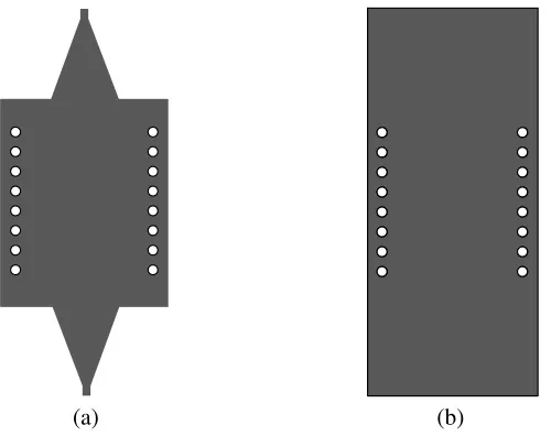
Figure 2. The configuration of CRLH SIW filter I (a) top view and (b) bottom view.
3 4 5 6 7 8 9 10 11 12 13 14
-80 -70 -60 -50 -40 -30 -20 -10 0
S 21 ,S11
/d
B
f/GHz |S11|
|S21|
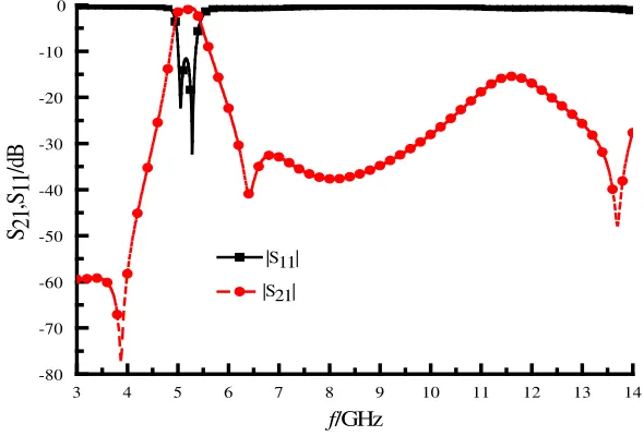
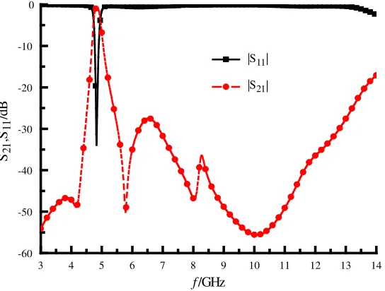
Figure 3. S-parameters of the CRLH SIW filter I.
of the CSRRs structure in an SIW cavity provides us with another degree of freedom to reduce the cavity resonant frequency. The filter is built on a Rogers RT/Duriod 5880 substrate with dielectric permittivity εr = 2.2, substrate thickness h= 0.508 mm and loss tangent tanδ = 0.0009. The diameter of metallic via holes d = 0.4 mm, and a center-to-center spacing of two adjacent holes d1 = 1.6 mm. The proposed filter has a symmetrical structure, and the input and output feeding lines are microstrip lines of 50 ohms. Simulation results can be found in Fig. 3, and the filter has good selectivity because of the transmission zero points outside the passband. In addition to 11–12.5 GHz, the S21in 6–14 GHz frequency band is less than −20 dB, so the filter has a good out of band suppression.
The CRLH SIW filter II shown in Fig. 4 with square-shaped CSRRs is etched on the bottom surface of the SIW cavity, with its top surface unchanged, which can enforce the high-frequency out-of-band suppression, increase the rectangular factor and reduce the cavity resonant frequency. Compared with the traditional right-handed transmission line, the bandpass filter proposed in this paper using the complementary split-ring resonators can significantly reduce the size of the device, which has right/left handed characteristic.
t2
c2
m1
m2
c1
t1
(b) (a)
Figure 4. The configuration of CRLH SIW filter II, (a) top view, and (b) bottom view.
-100 -80 -60 -40 -20 0 20 40 60 80 100
4.6 4.8 5.0 5.2 5.4 5.6
f
/GHz
Beta_p/rad
f/GHz
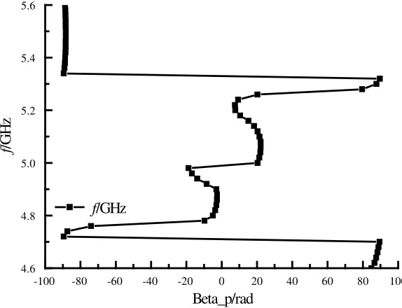
Figure 5. Dispersion curve of CRLH SIW filter II.
upper and rectangular CSRR structure on the bottom surface. It is shown in Fig. 5 that the value of dispersion curve is not only for positive, but also for negative, and the dispersion curves in passband pass through zero in passband. It can be concluded that this structure has the left and right hand characteristic, and is a composite left and right hand transmission line filter.
parameter extraction. The main formulas of NRW algorithm are as follows in Eqs. (2)–(5).
Z =
(1 +S11)2−S212 (1−S11)2−S212
(2)
n = 1
k1ha cos
1−S2
11+S212 2×S21
(3)
ε = n/Z (4)
μ = n×Z (5)
wherek1 =w0/c.
It is known that the composite right/left handed transmission line is composed of the material with negative permittivity properties and the material with negative permeability characteristics. By combining it with extracting equivalent parameters from the evolution of S-parameter, this paper will prove the rationality of the structure. Because the left handed structure designed accepts the size of sub-wavelength, which has a strict symmetry (including size and material), including rules of isotropic medium and a moderate thickness size (thickness of 0.508 mm, compared to the center wavelength, is neither “thick”, nor “thin”, and also is not half integer times of center wavelength), meaning that it is suitable for extracting equivalent parameters through the evolution of S-parameter by using NRW algorithm.
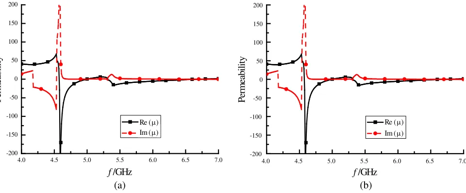
TheS-parameters obtained from the simulation are put into Eqs. (2)–(5), and the inversion results are shown in Fig. 6(a) and Fig. 6(b).
4.0 4.5 5.0 5.5 6.0 6.5 7.0
-200 -150 -100 -50 0 50 100 150 200 P erm ea b ility f/GHz Re (µ) Im (µ)
4.0 4.5 5.0 5.5 6.0 6.5 7.0
-200 -150 -100 -50 0 50 100 150 200 P erm ea b ility f/GHz Re (µ) Im (µ)
(b) (a)
Figure 6. Equivalent dielectric constant and equivalent permeability of CRLH SIW filter II. (a) The equivalent dielectric constant, (b) equivalent permeability.
S parameter inversion based on the unit model extracts the equivalent parameter, and one can see that the structure of the dielectric constant and magnetic permeability near 4.7 GHz changes from positive to negative, meaning that the filter has good characteristics of left hand, also proving that the changes through the dispersion curve make inference on the left hand properties.
3 4 5 6 7 8 9 10 11 12 13 14 -60
-50 -40 -30 -20 -10 0
S21 ,S11
/d
B
f/GHz
|S11|
|S21|
Figure 7. S-parameters of the CRLH SIW filter II.
2.2. Improved CRLH-SIW Filter
In the new CRLH-SIW filter III, the structures of bottom planes and the resonator structures of top planes do not change. The change is several slots etched on the tapered microstrip lines to improve the characteristic of outside band suppression at higher frequency as shown in Fig. 8. As shown in Fig. 9(a), the upper cutoff frequency moves downward and has no effect on the lower cutoff frequency. The passband of this CRLH SIW filter is composed of left-handed and right-handed passbands, and the cutoff frequency and bandwidth of this improved CRLH SIW can be controlled by adjusting the sizes of the gap of two slots etched units.
r1 r2 s1
s2
s3
(b) (a)
Figure 8. The configuration of CRLH SIW filter III considered by slot line, (a) top view, and (b) bottom view.
4 6 8 10 12 14 16 18 20 -60 -50 -40 -30 -20 -10 0 Frequency(GHz) S11r1=0.4mm S11r1=0.5mm S11r1=0.6mm S 21 r1=0.4mm S 21 r1=0.5mm S21r1=0.6mm
4 6 8 10 12 14 16 18 20 22
-60 -50 -40 -30 -20 -10 0 S-par am et er s (d B ) Frequency(GHz) S11r2=0.4mm S11r2=0.8mm S11r2=1.2mm S21r2=0.4mm S21r2=0.8mm S21r2=1.2mm (b) (a) S-par am et er s (d B )
Figure 9. Simulated S-parameters under different values of r1 and r2: (a) different values of r1, (b) different values ofr2.
Table 1. Design parameter value.
Parameter unit (mm) Parameter unit (mm) Parameter unit (mm)
a 0.1 c2 0.8 s1 0.5
b 0.3 m1 0.4 s2 0.5
a1 1.0 m2 0.3 s3 0.5
a2 2.8 t1 0.7 r1 0.5
c1 0.8 t2 2.1 r2 0.8
3. RESULTS AND DISCUSSIONS
To demonstrate the design, the proposed filter is fabricated and measured, which is presented in Fig. 10. With a standard of HFSS process, the total size of the filter is 0.24λg×0.61λg, including input/output tapered microstrip lines. The simulated and measured results are compared in Fig. 11.
As can be seen in Fig. 11, the center of the measured passband is at 4.9 GHz, and the 3 dB bandwidth is 0.2 GHz, which is a little bit narrower than that of simulation. The measured insertion
(b) (a)
2 4 6 8 10 12 14 16 18 20 -60
-50 -40 -30 -20 -10 0
S 21 ,S 11
/d
B
f/GHz
Simulated |S11|
Simulated |S21|
Measured |S11|
Measured |S21|
Figure 11. Simulated and measuredS-parameters for CRLH SIW filter III.
loss is around 2.8 dB, while the measured reflection coefficient is better than −14 dB. It can be found that the spurious response from 6 GHz to 21 GHz can be effectively suppressed by the gap of two slots on the tapered microstrip lines. Thus, the measured result of filter exhibits an upper stopband with 20 dB attenuation level extended to 4.3f0, while Fig. 5 shows the upper stopband with 20 dB attenuation level only extended to 2.8 f0 under the same conditions. The comparisons between the proposed structure and some other miniaturized bandpass filters are presented in Table 2.
Table 2. Comparison between the proposed and referenced filters.
Ref. S11 (dB) f0 (GHz)
Stopband
>20 dB IL(dB) Size (mm 2)
[15] 15 20 1.88 f0 2.78 1.62λg×1.46λg [16] 14 3.51 1.35 f0 1.74 0.45λg×0.67λg [17] 15 3.09 2.56 f0 1.34 0.79λg×0.37λg This Work 14 4.9 4.3f0 2.8 0.24λg×0.61λg
4. CONCLUSIONS
In this paper, an improved CRLH-SIW bandpass filter loaded with the proposed CSRRs has been designed, fabricated and measured. Due to circular CSRRs and square CSRRs respectively etched on the top and bottom surfaces of an SIW cavity and the two slots etched units on feeding lines, the proposed filter has a more compact size, as well as good insertion loss and stopband performance.
ACKNOWLEDGMENT
REFERENCES
1. Zhou, C. X., P. P. Guo, K. Zhou, and W. Wu, “Design of a compact UWB filter with high selectivity and superwide stopband,”IEEE Microwave and Wireless Components Letters, Vol. 27, No. 7, 636– 638, 2017.
2. Huang, L., W. Wu, X. Zhang, H. Lu, Y. Zhou, and N. C. Yuan, “A novel compact and high performance bandpass filter based on SIW and CMRC technique,” AEU — International Journal of Electronics and Communications, Vol. 82, 420–425, 2017.
3. Parameswaran, A., P. Athira, and S. Raghavan, “Miniaturizing SIW filters with slow wave Technique,” AEU — International Journal of Electronics and Communications, Vol. 84, 360–365, 2018.
4. Liu, Z., G. Xiao, and L. Zhu, “Triple-mode bandpass filters on CSRR-loaded substrate integrated waveguide cavities,”IEEE Transactions on Components Packaging and Manufacturing Technology, Vol. 6, No. 7, 1099–1105, 2016.
5. Yang, X., L. Xin, X. Jiao, P. Zhou, S. Wu, and K. Huang, “High-sensitivity structure for the measurement of complex permittivity based on SIW,”IET Science Measurement and Technology, Vol. 11, No. 5, 2017.
6. Choudhary, D. K., and R. K. Chaudhary, “A compact SIW based filtering power divider with improved selectivity using CSRR,”2017 Progress In Electromagnetics Research Symposium — Fall
(PIERS — FALL), Singapore, Nov. 19–22, 2017.
7. Zhang, H., W. Kang, and W. Wu, “Dual-band substrate integrated waveguide bandpass filter utilising complementary split-ring resonators,” Electronics Letters, Vol. 51, No. 2, 85–87, 2018. 8. Jin, J. D. and D. H. Yu, “Substrate integrated waveguide band-pass filter with coupled
complementary split ring resonators,” URSI General Assembly and Scientific Symposium (URSI GASS), Beijing, China, 2014.
9. Huang, Y. M., Y. Peng, Y. Zhou, H. Jin, S. Leng, and G. Wang, “Size-reduced dual-band HMSIW cavity filters loaded with double-sided SICSRRs,” Electronics Letters, Vol. 53, No. 10, 689–691, 2017.
10. Xu, S., K. Ma, F. Meng, K. S. Yeo. “Novel defected ground structure and two-side loading scheme for miniaturized dual-band SIW bandpass filter designs,” IEEE Microwave and Wireless Components Letters, Vol. 25, No. 4, 217–219, 2015.
11. Huang, Y. M., Z. Shao, W. Jiang, T. Huang, G. Wang, “Half-mode substrate integrated waveguide bandpass filter loaded with horizontal-asymmetrical stepped-impedance complementary split-ring resonators,”Electronics Letters, Vol. 52, No. 12, 1034–1036, 2016.
12. Chaudhury, S. S. and S. Awasthi, “Multiple passband circular cavity substrate integrated waveguide filter using asymmetric complementary split ring resonators,” 2017 IEEE Asia Pacific Microwave
Conference (APMC), Kuala Lumpar, Malaysia, 2017.
13. Nicolson, A. M. and G. F. Ross, “Measurement of the intrinsic properties of materials by time-domain techniques,” IEEE Trans. on Instrumentation and Measurement, Vol. 19, No. 4, 1970. 14. Weir, W. B., “Automatic measurement of complex dielectric constant and permeability at
microwave frequencies,”Proceedings of the IEEE, Vol. 62, No. 1, 33–36, 1974.
15. Zhu, F., W. Hong, J. X. Chen, and K. Wu, “Wide stopband substrate integrated waveguide filter using corner cavities,” Electronics Letters, Vol. 49, No. 1, 50–51, 2013.
16. Chen, F., K. Song, B. Hu, and Y. Fan, “Compact dual-band bandpass filter using HMSIW resonator and slot perturbation,”IEEE Microwave and Wireless Components Letters, Vol. 24, No. 10, 686– 688, 2014.