University of Twente
EEMCS / Electrical Engineering
Control Engineering
Patterns for dependable and distributed
embedded control
Mark Huijgen
M.Sc. Thesis
Supervisors
prof.dr.ir. J. van Amerongen dr.ir. J.F. Broenink dipl. ing. D.S. Jovanovic
August 2005
Abstract
The laboratory of Control Engineering of the University of Twente does research in the fields of embedded systems, mechatronics and robotics. One of the research projects is called Design Tools. This project focuses on the creation of a design tool called gCSP to facilitate the development of high reliable software for heterogeneous real-time control systems in a short time at a fraction of the present day costs. Key factors in this project are the safety and reliability of the designed software. The tool models software according to CSP, Communicating Sequential Processes. This is a process algebra that provides an easy way to reason about concurrent software without having to worry about
multithreading, locking etc. The CT library (Communicating Threads) provides a framework on which these CSP programs can execute. Current work is on a C++ version called CTC++.
The aim of this MSc project is to create a set of CSP-compliant software design patterns that increase the safety and/or reliability of the software they are applied to. The patterns have to be implemented in the CTC++ library. To accomplish this goal three generally well known design patterns have been investigated and implemented, namely Logging and Monitoring, N-Way programming and Watchdogs.
Although CSP/CT programs can be transparently distributed, there are some difficulties in
synchronously stopping distributed processes. A design pattern was created that specifically targets this problem.
The implemented patterns are demonstrated on the existing Tripod robotic setup. This setup consists of a platform connected via three arms to three linear motors. Safety and reliability of control software on such a setup are crucial factors.
The gCSP tool has support for applying the patterns to software models, facilitating easy use of them. Furthermore this project has made contributions to the CTC++ library with bug fixes and code cleanups and to the gCSP tool with bug reports and suggestions for improvements.
Samenvatting
De Control Engineering vakgroep van de Universiteit Twente doet onderzoek in embedded systemen, mechatronica en robotica. Een van de onderzoeksprojecten is Design Tools. De focus van dit project is de ontwikkeling van een software programma genaamd gCSP. Dit programma ondersteunt de
ontwikkeling van betrouwbare software voor heterogene real-time regelsystemen door middel van een kortere ontwikkel tijd en voor een fractie van de huidige kosten. Belangrijke punten in dit project zijn de veiligheid en betrouwbaarheid van de te ontworpen software. Het programma modelleert software volgens het CSP principe: Communicating Sequential Processes. Deze procesalgebra biedt een makkelijke manier om te redeneren over parallelle software zonder op details te hoeven letten als multithreading en mutuele exclusie. De CT bibliotheek (Communicating Threads) bied een raamwerk waarop CSP programma’s kunnen worden uitgevoerd. Huidig werk is aan een C++ versie genaamd CTC++.
Het doel van dit MSc project is om een set van CSP conforme, software ontwerp patronen te creëren die de veiligheid en/of betrouwbaarheid verhogen van de software waarop ze worden toegepast. Deze patronen moeten worden geïmplementeerd in de CTC++ bibliotheek. Om dit doel te bereiken zijn drie algemeen bekende ontwerp patronen onderzocht en geïmplementeerd, namelijk Logging and
Monitoring, N-Way programming en Watchdogs.
Desondanks dat CSP/CT programma’s gemakkelijk gedistribueerd kunnen worden, zijn er toch moeilijkheden bij het synchroon stoppen van gedistribueerde processen. Speciaal om dit probleem op te lossen is er nog een ontwerp patroon gemaakt.
De geïmplementeerde patronen worden op de bestaande Tripod opstelling gedemonstreerd. Deze opstelling bestaat uit een platform verbonden met drie armen aan drie lineaire motoren. Veiligheid en betrouwbaarheid van een dergelijke opstelling zijn van cruciaal belang.
Het gCSP programma heeft ondersteuning om de patronen toe te passen op software modellen zodat deze patronen gemakkelijk gebruikt kunnen worden. Daarnaast heeft dit project bijgedragen aan de CTC++ bibliotheek door middel van het repareren van fouten en het op schonen van de code. Tevens is een bijdrage geleverd aan de ontwikkeling van het gCSP programma door fouten en suggesties voor verbeteringen te melden.
Contents
1 Introduction ...1
1.1 Background...1
1.2 Software methodology...1
1.3 Safety, reliability, dependability...2
1.4 Objectives ...2
1.5 Outline ...3
2 Background and Tripod setup ...5
2.1 Introduction into CSP/CT and gCSP ...5
2.1.1 Processes ...5
2.1.2 Compositions...5
2.1.3 Primitive processes...7
2.1.4 Channels ...9
2.1.5 Parenthesizing ...9
2.2 Conversion from agent based control software to CSP software...10
2.2.1 Comparison ...10
2.2.2 Conversion...11
2.3 Tripod setup ...13
3 CSP/CT control software and distribution ...15
3.1 Non blocking synchronized stop in CSP/CT ...15
3.1.1 Solution: SyncStop ...15
3.1.2 Example program ...16
3.2 CSP/CT based control software for Tripod ...17
3.2.1 Linkdrivers ...17
3.2.2 Startup phase ...19
3.2.3 Servo control phase ...20
3.3 Possibilities for distributed control on Tripod ...24
4 Design patterns for safety and reliability...27
4.1 Logging and Monitoring...27
4.1.1 ProbeChannels...27
4.1.2 Framework for Logging/Monitoring components...28
4.1.3 Logging components ...29
4.1.4 Monitoring components...30
4.1.5 Function reference ...31
4.1.6 Example program using Logging/Monitoring pattern...31
4.2 N-Way programming...33
4.2.1 How to implement N-Way programming in CSP/CT ...33
4.2.2 Example program using the N-Way pattern ...34
4.2.3 N-Way exception handling...35
4.3 Watchdogs ...37
4.3.1 How to implement watchdogs in CSP/CT...37
4.3.2 Example program using Watchdog pattern ...39
4.3.3 Load measurement of CSP/CT program ...40
5 Case study: Patterns on Tripod...43
5.1 Logging...43
5.1.1 Data logging ...43
5.1.2 Other logging...44
5.2 Monitoring ...44
5.3 N-Way...45
6 Conclusion and recommendations... 49
6.1 Conclusions... 49
6.2 Recommendations... 50
Appendix A Working principle and drive of linear motor... 51
A.1 Working principle of linear motor ... 51
A.2 Drive of linear motor... 51
Appendix B Tripod computer hardware ... 53
Appendix C CDROM contents ... 55
1 Introduction
This project is about increasing software quality in the field of safety and reliability, the most important attributes of dependability for control systems. This has been accomplished by designing three generally applicable design patterns. These patterns are demonstrated on a robotic setup, where safety and reliability are often important factors. Robotic applications are often distributed and concurrent. A fourth design pattern is presented to solve synchronization in distributed CSP/CT software.
1.1 Background
This project is done as an MSc project at the laboratory of Control Engineering (CE) of the faculty EEMCS of the University of Twente. The main goals of this department are to investigate the applicability of modern systems and control methods to practical situations, mainly in the fields of mechatronics and robotics. In the past the department investigated the application of occam
programming language and transputer hardware for real-time control systems. The approach resulted in reliable, robust and well structured software. Nowadays transputers have become obsolete, but the software design method called Communicating Sequential Processes (CSP) is now applied to modern languages like Java, C and C++.
One of the projects from the group is the Design Tools project. The focus of this project is the development of a CASE (Computer Aided Software Engineering) tool using the CT library
(Communicating Threads), which allows for building high reliable software for heterogeneous real-time control systems in a short real-time at a fraction of the present day costs. In this project safety and reliability of the designed control software are key factors.
1.2 Software
methodology
In the process of designing an embedded control system four different design phases can be distinguished (Figure 1-1).
Figure 1-1 Design trajectory for embedded control systems
without having to worry about low-level concepts like multithreading, locking etc. The earlier mentioned CT library (Hilderink, 2005) developed by the group implements this CSP model. Current work is on a C++ version called CTC++ (Orlic and Broenink, 2003).
To get from a 20-sim model directly to an implementation based on CSP/CTC++ is a big step, especially for complex systems. To divide this step into smaller steps a tool was created as part of the design tools project called gCSP (Jovanovic et al., 2004). This tool can be used to model CSP software
graphically. It provides functionality to generate machine readable CSP code (CSPm) for formal checking to do an extra verification step and code generation to generate an implementation that can run on the CTC++ library.
Control systems are generally real-time. Real-time in this context means that processing the inputs, calculating the control law and preparing the outputs must be completed within a fixed amount of time. The work has to be completed before the deadline. For software development this means for example that all memory has to be allocated before starting real-time processing.
The real world is a concurrent place. Concurrency in software introduces problems like deadlock and livelock. This makes concurrent programs harder to verify then sequential ones. The CSP/CT provides a structured way to use concurrency in software without having to worry about these problems. Control software can benefit from concurrent software because then it can better match the real world.
1.3 Safety, reliability, dependability
Dependability of a system is determined as a combination of various important system quality attributes. An overview of these attributes is given in Figure 1-2.
Figure 1-2 Dependability attributes according to (Avižienis et al., 2004)
Two of these attributes are of main interest in this MSc project, namely safety and reliability.
Safety
Safety of a system is its freedom from those conditions that can cause death, injury, occupational illness, damage to (or loss of) equipment (or property), or environmental harm, (Leveson, 1995).
Reliability
Reliability of a system is taken to be a measure of the success with which a system conforms to some authoritative specification of its behaviour, (Randell et al., 1978).
1.4 Objectives
Logging and monitoring
This pattern provides a means to log data in real-time for later analysis. This pattern can for example be used for debugging during development, increasing the overall reliability of the final program. It can also be used in the final program to record important events like (imminent) failure of (parts of) the system. It can even increase the maintainability of a system. The second part of this pattern, monitoring, can be used to increase the safety of a system. A monitoring component can watch certain values in a system and take action if they get out of hand.
N-Way programming
This pattern mainly increases the reliability of a system by introducing redundancy. It uses multiple independent versions of a component with the same functionality and may do error correction. With error correction it is possible to continue working in cases of failure of some parts of the system, where without this would not be possible, thus increasing the reliability of the system. The pattern can also abort the redundant components if an unrecoverable error is detected, this can then be used to start a safety component. This can increase the safety of a system.
Watchdogs
This pattern mainly increases the safety of a system by checking if the system is alive. If a certain software component does not signal the watchdog that it is still running the watchdog can intervene. This intervention can range from just logging the event to aborting a part of a program and starting a safety component.
By nature of CSP programs designed according to this paradigm are easy to distribute: one can
distribute processes as long as the communication relationships remain intact. A pattern was created to provide a means to synchronously stop multiple processes called Synchronous stop.
The applications of these implemented patterns will be demonstrated on the existing Tripod robotic setup. This setup consists of three vertically mounted linear motors connected to a single platform. When dealing with moving robots, safety is an important issue. Safety mechanisms are needed to prevent the robot from inadvertently harming others as well as itself. To be able to demonstrate the design patterns on Tripod its multi-agent based control software (Breemen, 2001; Eglence, 2003) has to be converted to CSP/CTC++ software.
1.5 Outline
Chapter 2 describes some of the theoretical and practical background that are important to this project. It also give a comparison of agent based software and CSP/CT software. Finally it presents the Tripod setup.
Chapter 3 presents the pattern for distributed synchronized stop demonstrated on an example. Second it describes the new CSP based control software for the Tripod setup and does some suggestions for distributed control of this setup.
Chapter 4 treats the three design patterns for increased safety and reliability: Logging and Monitoring, N-Way programming and last Watchdogs. All patterns are demonstrated with example programs. Chapter 5 discusses the application of the three design patterns on the Tripod setup in the same order as chapter 4 did. It shows how the patterns were applied and what the results are.
Chapter 6 contains the conclusions and recommendations of this project.
2 Background and Tripod setup
This chapter presents the theoretical and practical background of this project. First an introduction to gCSP is given, a graphical modelling language for CSP programs. The second section discusses the similarities and differences between agent based software and CSP/CT based software. Last a description of the Tripod robotic setup is given.
2.1 Introduction into CSP/CT and gCSP
This section introduces the concepts of CSP/CT and how they are modelled by the gCSP tool. It starts by introducing the concept of processes and how they can be put in a composition. Then the primitive processes that are available in the CT library will be treated. How processes communicate is explained in the fourth subsection. Finally parenthesizing in graphical models is introduced.
2.1.1 Processes
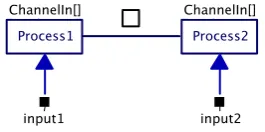
A process is an independent entity that performs a specific task. It does not know of the existence of other peer processes, but it can be a collection of other processes (children). It can only communicate with other processes or the environment via channels. In gCSP a process is represented by a rectangle with a name in it like Process1 and Process2 in Figure 2-1. The figure also shows an arrow between the two representing a channel used for communication between Process1 and Process2, channels will be explained in subsection 2.1.4. The straight line is the compositional relation between the processes, in this case it means that the processes execute in parallel, compositional relations will be explained in the next subsection.
Figure 2-1 gCSP diagram with two communicating processes running in parallel
2.1.2 Compositions
Figure 2-1 shows a relation with the parallel operator, meaning that the two processes execute in parallel. In total there are seven compositional relations that can exist between processes. Table 2-1 shows all operators. The watchdog operator is a contribution of this project, see section 4.3
Table 2-1 The seven compositional relations in CSP/CT
Sequential Parallel Alternative PriParallel PriAlternative Exception Watchdog
Sequential
This operator says that the processes in the relation will be executed sequentially in the order the arrow indicates, in the case of Figure 2-2 first Process1 will execute and when that one is finished Process2 will execute. After the last process finishes the construct is also finished.
(Pri)Parallel
This operator says that the processes are executed in parallel (concurrently). The parallel version does not have priorities and gives all processes in the construct an equal chance of executing. The
prioritized version gives a higher priority to the process it is pointing to; in the case of Figure 2-3 Process1 has a higher priority then Process2. The construct finishes if all the processes in it have finished.
Figure 2-3 PriParallel composition
(Pri)Alternative
This operator actually works on guards in stead of processes. However each guard has a process associated with it. Alternative is about making a choice, the construct chooses the first guard that is ready and runs the associated process. After the process finishes the construct finishes also. If there are multiple guards ready at the same time only one is chosen. All guards have an equal chance unless the prioritized version of the operator is used. The prioritized operator chooses the guard with the highest priority indicated in the same way as with PriParallel. Figure 2-4 shows two guards with processes in an alternative construct. The guards are indicated by ChannelIn[], in this case they will become ready if the associated channel is ready for communication (e.g. when a process on the other end of the channel wants to write to it).
Figure 2-4 Alternative composition
A guard can also work on an output channel; it will become ready when the other side wants to read from that channel. Third there is the SKIP guard, which is always ready. Guards also can have a condition between the brackets like [variable >= 1], the guard can only be ready when this condition is true.
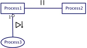
Exception
The exception operator makes it possible for a process to handle exceptions thrown in another process. For example if Process1 (Figure 2-5) throws an exception it will abort and the exception can be handled by Process2. Process2 is drawn as an ellipse despite the fact that it is a normal process just like Process1. Exception handlers are drawn differently so a user can clearly see what part of the program is for exception handling.
Figure 2-5 Exception composition
Figure 2-6 Parallel composition inside an exception composition
More information on exception handling in CT can be found in (Engelen, 2004).
Watchdog
The watchdog operator (Figure 2-7) is a contribution of this project and is explained in detail in section 4.3.
Figure 2-7 Watchdog composition
2.1.3 Primitive processes
This subsection treats the primitive (processes) that are available in gCSP. Described are repetitions, codeblocks, readers and writers, barrier with syncer processes, linkdrivers and last watchdog
operations.
Repetition
A repetition primitive can conditionally restart the process (or construct) it is coupled to. An example is given in Figure 2-8, where Process1 is restarted until the condition ‘!stop’ becomes false. The relation between a repetition and the process it works on is always sequential. The direction of the sequential operator determines if the condition is a pre-condition (while[condition] do {…}, Figure 2-8) or a post condition (do {…} while[condition]).
Figure 2-8 Repetition construct
Readers, Writers and Codeblocks
A reader is a primitive process that reads from a channel and puts the result in a local variable. The writer process does the opposite; it takes the content of a local variable and writes it into a channel. After their action is performed they finish. Readers/writers can be made aware of their local variable by means of a varchannel. The example in Figure 2-9 first reads from the input channel. Then the codeblock does some processing on the variable read and places the result in the output variable. The writer then writes the result into the output channel.
Figure 2-9 Reader to codeblock to writer
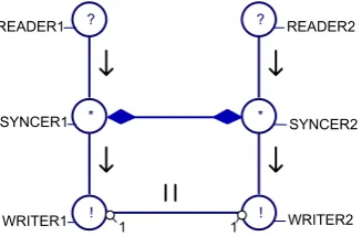
Barrier with syncer processes
A barrier is a method to synchronize multiple independent processes. A barrier synchronizes syncer processes. When a syncer executes it becomes ready and it will suspend until the barrier becomes ready, the barrier becomes ready when all its associated syncers are ready. All syncers then resume execution. An example is shown in Figure 2-10, where to parallel branches synchronize after reading from their channels (channels are not shown here). The barrier is represented by a line with on both sides a diamond shape, a syncer process is represented by a circle with a * in it.
Figure 2-10 Two parallel branches synchronized with a barrier
Linkdrivers
Linkdrivers can provide an interface between a CSP/CT program and the environment, for example hardware (Hilderink, 2005). An output link driver is modelled as a reader that reads a value from a channel and converts it to a form acceptable for the environment. Since the reader link driver reads from a channel, although it models an output port from the software, it is depicted as an inverted reader icon. Figure 2-11 shows both a writer linkdriver (from which Process1 reads) and a reader linkdriver (to which Process1 writes).
Figure 2-11 Linkdriver writer and reader
Watchdog operations
Watchdog operations are depicted by shield symbols; there are three of them (Figure 2-12). Every shield has a letter inside. S is for starting a watchdog, H is for hitting the watchdog and R is for stopping (removing) the watchdog. The operations can be put in compositional relations just like other processes. The watchdog is explained in more detail in section 4.3.
2.1.4 Channels
In CSP processes communicate via channels. A channel conveys a message from one side to the other. In CSP this can be bidirectional communication, but in CSP/CT the channels are unidirectional. By default the communication is done synchronously, two processes rendezvous before the message is passed. Channels are indicated in gCSP by arrows with a closed arrowhead (see Figure 2-1). Since message passing is synchronous a channel between two sequential processes or between two processes in the same alternative is a design error.
A channel can be replaced by a probe channel. Probe channels help to facilitate the logging system contributed by this project and are discussed in more detail in subsection 4.1.1. Graphically they differ from the normal channel in thickness and colour.
The second form of channels in CSP/CT is called a varchannel and its abstraction in CSP is variable. Communication in a varchannel happens asynchronously. A varchannel can be seen as a shared variable between processes. These channels should not be used between parallel processes because race conditions can occur. They are useful for example to pass a value between a reader and a codeblock as happens in Figure 2-9, they are indicated with an open arrowhead.
Channels can be poisoned, also called rejected. At the time a channel is poisoned an exception is stored inside and when a process attempts to read from or write into this channel it will throw the stored exception.
2.1.5 Parenthesizing
Consider the gCSP diagram in Figure 2-13. This model has compositional ambiguity. Without compositional grouping it would not be clear which execution behaviour is desired. For example it could be that (5 -> 1) || 2 || (3 -> 4) but also (5 -> (1 || 2)) || (3 ->4).
Figure 2-13 Compositional ambiguity
In the diagrams the parenthesizing is done with bubbles with a numeral index (Figure 2-14). The image also has boxes drawn to complement these bubbles. This also explains how the index number comes to be: it is the number of boxes that cross on that side of the relation. In this diagram boxes make it easier to understand the parenthesis, but in more complex diagrams they tend to clobber the diagram. Figure 2-14 shows (5 -> (1 || 2)) || (3 ->4).
2.2 Conversion from agent based control software to CSP software
To demonstrate the patterns on the Tripod setup, first the existing Tripod software needed to be converted to run on the CTC++ library in which the patterns will be implemented. The existing software for Tripod is agent based (Breemen, 2001), (Eglence, 2003). This section describes the main differences between agent based software and CSP based software with respect to structure and execution framework. It also describes the steps necessary to convert agent based software to a CSP/CTC++ based implementation.2.2.1 Comparison
Agent based software consists of one or more agents. Each agent can handle a specific task. Agents can be grouped with a coordination object, see Figure 2-15. This object controls what agent(s) of the group can be active at a given time. CSP based software consists of processes. Processes can be grouped in a hierarchy in which they can run in parallel, in sequence or alternative to each other. The relation between agents and processes and the relation between coordination objects and the CSP hierarchy will be treated in this subsection.
Figure 2-15 Two agents in a Parallel coordination object
Execution
The main difference in execution between agents and processes is the fact that agent based software calls agents each period to perform their job and CSP/CT processes are started once and continue to do their job until the process itself stops.
The agent framework checks every period if an agent wants to be active. Depending on the
coordination object associated with the agent it is then decided if the agent actually is allowed to run this period. If so the agent is called to perform its job for that period. Execution of agents is controlled centrally by the framework.
CSP has no real notion of time. Processes are started by the framework, but will only stop if they decide to do so. The framework itself cannot just stop processes; execution is controlled decentrally by the processes themselves (more on this in the next subsection about communication).
The second important difference is that the agent framework is running in a single thread, this in contrast to the CSP model where each process could be a separate thread and really execute concurrently.
Communication
Another key difference is in the communication between agents versus the communication between processes. In the agent framework communication is done via ports. Upon creation of an output port a local variable is coupled to this port. Writing to the port is performed by just modifying this variable. Reading from a port however is done via the port itself with the method port->getValue().
this is not a problem since it is single threaded. This is the main advantage of the agent framework, it is light weight, but also its disadvantage, no real concurrency.
In CSP communication between processes is performed via channels. In CSP writing and reading is done via the channel itself. The default channel behaviour is to let the processes rendezvous before exchanging data. This means if a process wants to write to a channel it will suspend until there is also a process on the other side of the channel that wants to read from it. This is how control of execution is decentralized in CSP.
Implementation
The main implementation difference between an agent and a process is the number of operations it has. Operations as in the sense of member functions of a C++ class. A process has only one public function: run(). The agent equivalent to this is calculate() (or sense() in case of a sensor agent
or actuate() in case of an actuator agent, see Table 2-2). Consider an agent/a process that
implements a simple controller. Calling the calculate function will result in one step, and calling the run function will result in running the controller until it determines to stop. Agents also have got the following extra functions with respect to processes: start(), stop(), initialize(),
finalize() and activation(). When converting agent software to CSP/CTC++ software, start
and stop can be integrated into the constructor and destructor of the process. The initialize and finalize function can be integrated at the start and end of the run function. Since the activation function
describes when an agent wants to be active it can be used by the new process to determine when to stop and/or could be used to enable/disable the guard if the process is used in an alternative construct. It can be concluded that the CSP/CT framework in this respect is simpler to understand and use.
Table 2-2 Agent types vs. CSP
Agent types CSP Controller agent Process
Sensor agent (Input) Linkdriver Actuator agent (Output) Linkdriver
2.2.2 Conversion
Knowing the main differences between agents and processes, it is possible to convert agent-based software to CSP based software. This subsection presents a number of steps that can be used as a guideline to accomplish this conversion. Since only one agent program was converted, this guide may not cover all possible agent constructions.
The easiest way is to start with a new .cpp and .h file for each agent that will be converted to a process. Create a class derived from process and create a constructor and an empty run function. Start with converting all elementary agents (agents that don't contain other agents) to processes.
• Copy initialization code from agent constructor to constructor of process
• Copy code from start() function to process constructor
• Copy code from stop() function to process destructor
• Copy code from agent destructor to process destructor
• Create a variable and channel for each port.
• Copy code from initialize(), calculate(), finalize() into run().
• Add around the code copied from calculate() a while(condition) construct, since
timing is now implicit via channels. The expression for 'condition' depends on the desired behaviours of the agent, most importantly when to stop. The condition has to be determined by studying the code of the agent.
• Find where port variables are assigned a value and add a
channel->write(&variablename) directly thereafter.
• Find where port variables are read in the code and add a channel->read(&variablename)
Now convert sensor and actuator agents to linkdrivers so they can be triggered on external events, e.g. a timer. The same steps as with an elementary agent should be taken, except that calculate() is
called sense() in case of an sensor agent and actuate() in case of an actuator agent.
In the case of a timed input linkdriver, a read call will suspend the calling process until the linkdriver unlocks it, for example on a timer interrupt. However caution is advised when a process has to read multiple timed linkdrivers that have the same period. This needs to be done with a number of reader processes in a parallel construct. In this way all readers will be unlocked at the same time by their respective linkdrivers. If you would read in sequence, the read call on the first channel will suspend the process and on the next timer interrupt it will resume again. Now the second read takes place, which will again block. Now the reading takes two periods! (Or more of course, depending on the number of sequential reads.)
The last step in the conversion is mapping agent coordination objects to CSP/CT compositional relations. The different types of coordination objects as well as the different CSP compositions are in Table 2-2. For each coordination object its equivalent CSP composition will be presented.
Table 2-3 Coordination objects vs. compositions
Coordination objects CSP compositions Independent Parallel
Cooperative Master-slave Cooperative Fuzzy addition
(Pri)Parallel Competitive Fixed priority (Pri)Alternative Competitive Sequential
Competitive Cyclic Sequential
Independent Parallel
This means that agents work independently in parallel to each other. This maps to parallel interleaving processes in CSP/CT.
Cooperative Master-Slave
This means that when the master agent is active, the slave agent(s) is(are) also active. In most
situations this directly maps to parallel processes in CSP when there is direct communication between the processes. In this way the master-slave principle will be taken care of by the rendezvous of the channels.
Cooperative Fuzzy addition
This coordination object cannot be mapped directly; an extra process is needed to do the fuzzy addition. The output is a function of the outputs of all the agents taking part. The coordination object can also handle the situation when not all agents are active, so it only takes the active agents into account. With CSP this exact behaviour is somewhat difficult due to the rendezvous behaviour of channels.
Competitive Fixed priority
The agent with the highest priority that also wants to be active may run this period (and the others not). This maps to pri-alternative processes in CSP/CT. There is a difference however, with
competitive fixed priority each period the framework chooses which agent is run. So if an agent with a higher priority also wants to be active that one is chosen. With CSP/CT the chosen process will keep on running until it decides to stop, also if a higher priority process in the pri-alternative wants to be active.
Competitive Sequential
Competitive Cyclic
The behaviour of cyclic coordination is the same as sequential, with the added rule that when the last agent ends, the first one is activated again. This maps to sequential processes in CSP/CT with repetition.
2.3 Tripod
setup
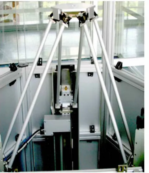
Tripod is a simplified version of a Stewart platform (hexapod). It is constructed by Imotec B.V. Whereas a Stewart platform has six degrees of freedom, the platform of Tripod only has three, namely translation along the x-, y- and z-axis. By construction the platform is always aligned in the x-y plane. The three arms connected to the platform can all be moved individually along the z-axis by three linear motors. A photo and schematic drawing of the Tripod setup are shown in Figure 2-16 and Figure 2-17 respectively.
Figure 2-16 Photo of Tripod setup Figure 2-17 Schematic view of Tripod setup
An arm actually consists of two arms in a parallelogram construction together with the platform and a translator (linear motor). A detail of the connection to the translator is shown in Figure 2-18. The joints connecting the arms to the translator only allows rotation in the φ and θ direction. The connection of the arms to the platform is similar.
The position of the linear motors is measured with a linear quadrature encoder. Besides the usual quadrature signal and index signal, this encoder is also equipped with end switches at both ends and a signal that indicates if the motor is at the lower or upper half of its stroke. This last signal can be used to check if the motor is below the index marker on the encoder before calibration is started.
The safe working area of the platform is a cylinder shape with a radius of 200 mm and a height of 250 mm. If the platform exceeds this area, the leaf springs in the joints or even the joints themselves will be damaged. In (Eglence, 2003) the following formulas are given to approximate the distance from the center (pappr) and the height (zappr) of the platform, these should stay within respectively the radius and height of the safe working area. In the second formula l is the length of an arm which measures 541
mm and r is the radius in which the three motors are positioned which amounts to 300 mm.
2 3 3 2 2 2 3 1 2 1 2 1 246 . 0 z z z z z z z z z r
pappr = − − + − +
149 . 0 ) ( 355 . 1 3 2 2 2 2 2 3 2
1 + + + − − − − +
= z z z l r p l r
zappr appr
Because these formulas are approximations the safe limits are somewhat lower then 200 mm for the radius and 250 mm for the height. According to (Eglence, 2003) the safe values are 170 mm for the radius and 234 mm for the height. With these limits the platform can never move beyond the safe working area.
Information on how linear motors work can be found in Appendix A. Information on the computer hardware included in the Tripod setup can be found in Appendix B. Finally some other interesting technical specifications of the Tripod:
Max. stroke linear motors 520 mm Max. speed 1.5 m/s Max. acceleration 30 m/s2
3 CSP/CT control software and distribution
This chapter discusses the new Tripod CSP/CT control software for Tripod. During the development problems were encountered with synchronization. The solution for this problem is treated first in this chapter. Then a description of the new Tripod software and finally some suggestions for distributed control on Tripod.
3.1 Non blocking synchronized stop in CSP/CT
There are different types of synchronization possible between processes. One of them is barrier synchronization between N processes. When a process reaches the barrier it will wait until all other processes have also arrived. At that moment data may be exchanged and all processes will continue execution. This form of synchronization has one problem however: processes will block. This blocking is unwanted in the case of those processes being controllers. What one wants is to keep controlling. Only when all controllers are ready to stop, they stop together.
3.1.1 Solution: SyncStop
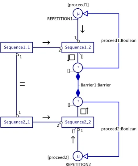
The solution to the blocking problem is given in Figure 3-1. Two sequences of processes need to terminate synchronously when both sequences are running the last process. None of the processes SequenceX_2 may block on this synchronization. The solution is to put the last process of each sequence in an alternative with a syncer process, with all syncer processes linked to the same barrier. A repetition that may be inside the last process has to be placed outside of the alternative; otherwise the SequenceX_2 will run indefinitely because the alternative can never select the syncer process. As soon as all sequences (in this case two) are running their final alternative construct, the guard on the barrier becomes ready. This will run the barrier synchronization and some code to modify the repetition condition to break the loop. It this case the sequence ends, but it is possible that each sequence continues with another process. This pattern works also if the two sequences run on separate systems.
3.1.2 Example program
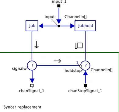
At the time of writing the library does not yet support syncers and barriers. Here a design pattern is provided that achieves the same functionality with basic communication primitives like readers, writers and channels. This example contains three sequences in parallel called worker_1 to worker_3 (Figure 3-2). The workers together are called a crew. The other figure (Figure 3-3) shows one sequence (one worker). A sequence consists of two processes: job and jobhold. Input represents the data processed by either job or jobhold.
Figure 3-2 Barrier replacement
Figure 3-3 Syncer replacement
The barrier in this example works as follows:
• Once a Job process terminates the ‘syncer’ signals the ‘barrier’ that it is ready to rendezvous and then goes into the alternative with jobhold. The repetition is omitted in the diagram.
• Once all three workers have signalled the ‘barrier’ the parallel with the readers ends (Figure 3-2). In sequence a parallel with writers is started that will communicate back to the syncers.
• All three alternatives will now run the reader part of their ‘syncer’ and all sequences terminate.
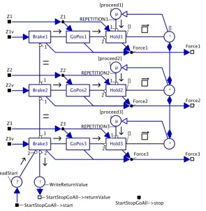
3.2 CSP/CT based control software for Tripod
The agent software that is used as a basis for the new CSP/CT version was created by M. Eglence for his MSc project (Eglence, 2003). The code for the controllers and hardware drivers are reused in this project.
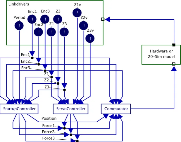
An overview of the top level of the program is shown in Figure 3-4. The square at the top contains the linkdrivers that communicate with the hardware (or with the 20-sim simulation model). They are read by the processes below them. The Commutator process interfaces again with the hardware or
simulation model. Lastly the hardware or simulation model closes the loop.
Figure 3-4 Top level of Tripod control software
The program can be compiled in two versions, one that is targeted for controlling the real hardware setup and a version that uses generated C-code from a 20-sim model. The first version only works for the DOS operating system, since this is the only operating system for which the CSP/CT library provides strict timing. The simulation version can be compiled for the DOS and for the Linux operating system.
First the linkdrivers will be treated. Then the startup phase of the Tripod, controlled by StartupController. The third subsection will treat the servo control phase, controlled by the ServoController process.
3.2.1 Linkdrivers
Table 3-1 Linkdrivers in the Tripod control software
Linkdriver Functionality
DigInput Provide the status of the start and stop button plus the ‘vrijgave’ (enabled) status of the robot. Secondly it provides the status of the endswitches and ‘at lower/upper half’ / ‘at upper half’ information for all motors. DigOutput Provides the ability to enable / disable the
motor amplifiers
Encoder Provides three raw encoder values, three absolute positions and three first order derivatives of the position (speed). Commutator/DAOutput Reads three forces and applies them to the
three axes.
For the Tripod program two versions of the linkdrivers were created: one to interface with the real hardware and one to interface with the 20-sim model of the hardware – by just replacing the linkdrivers the program can use a simulation model of the robot.
Hardware version
The hardware versions of the linkdrivers serve as an interface to the Tripod hardware. The Tripod hardware is connected to the controlling computer via three interface cards: one encoder card that is connected to the measurement rulers, one digital I/O card used for buttons and a D/A converter to steer the amplifiers (see Appendix B for more information about the computer hardware).
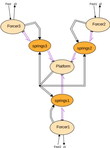
Simulation version
The simulation versions of the linkdrivers serve as an interface to a 20-sim model (Figure 3-5). This 20-sim model models the mechanical hardware. It takes three forces as inputs and provides the three motor positions as outputs. The same model was also used by Eglence for his MSc project (Eglence, 2003). It is a simple model, for example the influence of gravity is omitted. The accuracy is also not good enough to design a controller for example. The model is however accurate enough to check if the new Tripod program behaves as expected. Important to check are the start and stop time of all
processes with respect to each other and to check if the program doesn’t behave erratically. Because of the inaccuracy the model is unstable with the controller parameters that are used for the hardware version. All K parameters of the PID controllers in the program are adjusted when compiling the simulation version.
From this 20-sim model C-code was generated. This code is then used by the simulation versions of the linkdrivers. The Encoder linkdriver takes the position from the model and the Commutator writes the forces to the model and calls the XXCalculateSubmodel() function to update the model.
Fext Fext1
Fext2
z3 z2
z1 Forcer1
Forcer2 Forcer3
Platform
springs1
springs2 springs3
Figure 3-5 20-sim model of the mechanical hardware of the Tripod setup
3.2.2 Startup phase
The StartupController takes care of preparing the Tripod for servo control. This mainly consists of aligning the linear motors and calibrating the encoders. For working principles and the need for aligning the linear motors, see Appendix B. During this process the platform will be raised and then lowered to a position that is a couple of centimetres above the lowest possible position. This process consists of four distinct phases, handled by four different processes: ChkStart, Align, Calibrate, GoHomePID (Figure 3-6).
Figure 3-6 StartupController process
ChkStart
lower half and the switches have to be active, since all the motors should be at the lower end of their respective strokes. If everything checks out, the next process will run.
Align
This process aligns all motors one pitch above their lower end position. One pitch is the distance between two coils in the linear motor (see Appendix A). This is performed in three sub phases. First the force on all motors will be increased, keeping the position sent to the Commutator zero. This will make each motor move to a detent position, unless it is at the end of its stroke. Hereafter the position sent to the Commutator is increased while holding the force constant. This will move the motors up one pitch. This ensures the motors are no longer at the end of their strokes. The third phase will increase the force again to prepare for the next phase. Now the encoder counters are reset to the middle of their range.
Calibrate
This process will locate the index pulse on the encoders. It first sets the hardware linkdriver Encoder in calibration mode. Reading from the encoder now results in the contents of the index latch of the counters. Then it will increase the position sent to the Commutator, the force will remain the same value set by the Align process. All motors should now move up. When the position has been increased enough to make sure all motors have moved past the index pulse, a check is done to see if this is indeed the case. Then Encoder linkdriver is put in normal mode again and the final phase starts. GoHomePID
This is the first closed loop process. It will steer all motors back from the final calibration position to a couple of centimetres above the lower end of stroke. When all motors have reached this position, the Encoder linkdriver is told to make the current position the absolute position 0. The Tripod hardware is now ready for control by the ServoController process.
3.2.3 Servo control phase
Servo control is handled by the ServoController process. During servo control the control software can be in several modes. Each of these modes has its own control function within the program, for
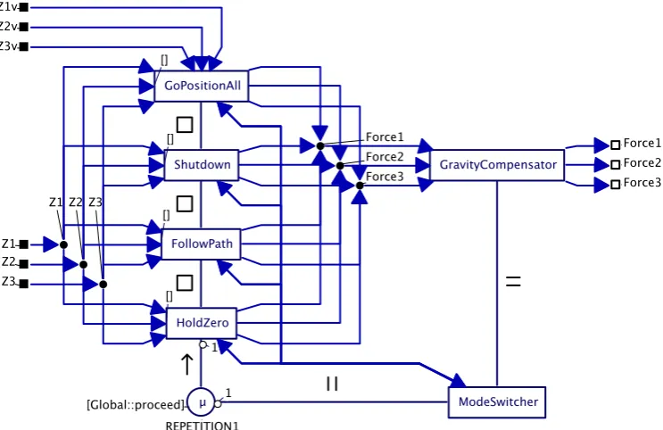
example one mode holds the platform at the zero position and another mode controls the robot along a given path. A mode can be activated by the ModeSwitcher process and only one mode can be active at a given time. Once a mode has been activated, it can only be deactivated by itself, but the
ModeSwitcher has the possibility to negotiate deactivation of certain modes via channels. The internals of the ServoController process are shown in Figure 3-7. The channels to/from the ModeSwitcher process will be treated in the paragraph on mode transitions at the end of this subsection.
Figure 3-7 ServoController process
GoPositionAll mode
Figure 3-8 GoPositionAll process
Shutdown mode
This mode may only be activated when the robot is at position zero with speed zero. The purpose of this process is to lower the motors to just above the lower end stops before turning off the amplifiers. When this mode is finished the program should end (or restart). The process consists of only three PID controllers in a parallel relation; therefore no diagram is shown here.
FollowPath mode
Figure 3-9 FollowPath process
HoldZero mode
The sole purpose of this mode is to hold the platform at zero when no other mode controls the robot. The position and speed should be zero before entering this mode. The mode becomes active after receiving a value through the start channel (StartStopHoldZero->start on the top left in Figure 3-10) from the ModeSwitcher. It sets some initial values in the Init code block and starts an alternative in repetition. In the alternative are three controllers (one for each motor) and the reader of the stop channel. The repetition continues until a value is received on this channel. When this has happened, the mode will end by writing a return value into the returnValue channel on the bottom right of Figure 3-10.
ModeSwitcher process
As stated earlier the ModeSwitcher process determines which mode becomes active. Which mode is chosen depends on external inputs (like buttons and keyboard) and internal feedback (return value from the mode that ended). All possible mode transitions are indicated in Figure 3-11.
HOLD
GOALL FOLLOW SHUTDOWN
FollowPath Aborted or Stop pressed
Start pressed
GoPositionAll ended
FollowPath
ended Stop pressed Init
Figure 3-11 Mode transitions in the servo control phase
The ModeSwitcher is connected to each mode process with a so called StartStopChannel. This
‘channel’ actually is a combination of three channels, a start channel, a stop channel and a returnValue channel. The start and stop channel are from the ModeSwitcher to the mode and the returnValue channel is from the mode process back to the ModeSwitcher. To start a mode the ModeSwitcher writes to the start channel belonging to that mode. Some modes can be asked to stop; this is done by writing to the stop channel. A mode writes a return value back to the ModeSwitcher through the returnValue channel when it finishes. This return value can influence what mode is to be activated next. For example when the Follow mode ends prematurely due to an exception, or when it is asked to stop before it is done, the return value will indicate this. The ModeSwitcher now knows that the GoAll mode should be activated.
3.3 Possibilities for distributed control on Tripod
A possible distributed control system can be done as follows with four nodes:
• Hardware driving node with safety checks.
• Control node(s), implementing the actual controllers.
• Setpoint/Path generation node.
• (G)UI node.
This setup is depicted in Figure 3-12.
The hardware driver node provides position/speed feedback outputs to and accepts force as input from the controller nodes. It can also do safety checks, like checking endswitches, if the robot is in its workable region, checking if the current speed/acceleration doesn’t cross the safe limit. It is possible for this node to intervene by switching to an internal safety controller if those limits are crossed. This allows also for safe testing of new controllers in the controller node. The hardware driver node should also do the startup phase and hold the platform until a control node is available to take over control. The control node accepts setpoints from a setpoint node and feedback from the hardware driver node. It contains the control law to calculate the force and provides it back to the hardware driver node. The setpoint generation node provides setpoints to the controller nodes. The setpoints may be loaded from a file, or generated from data received from the (G)UI node. This last feature makes it possible to manually control the robot with for example joysticks or keyboard.
4 Design patterns for safety and reliability
This chapter presents three design patterns that can help to increase the safety and reliability of CSP/CT software. First the Logging and Monitoring pattern is discussed; it provides a means to log data for on- or offline analysis and via monitoring the ability to intervene if wrong data is detected. The second pattern is N-Way programming. This pattern achieves extra reliability through redundancy by making it possible to run multiple versions of a process in parallel and comparing their outputs. The last pattern that is discussed is the Watchdog pattern. This pattern is mainly intended to increase the safety of a system by intervening if (a part of) a program locks up.
All patterns are designed to be used in a real-time program; all actions take a fixed or a bounded amount of time. They all have as requirement that little changes to the processes in a CSP/CT program are required to make use of them.
4.1 Logging and Monitoring
Logging is useful for a number of purposes, for example debugging during development, logs can be used for maintenance (to prevent or solve problems), or in the case of a more serious event it can help in legal issues like liability. In general: a logging component stores data for later analysis, but the stored data can also be used for on-line presentation and adaptation.
While logging is passive, in the way that it does not react to anything it receives and only stores data, monitoring is an active pattern. A monitoring component can react to data it receives, for example if it detects that the data is wrong. Action can then be taken to correct the problem.
In this section a framework is presented that provides logging and monitoring within the CSP/CT architecture. Logging and monitoring (L/M for short) is divided into two classes of components that are interchangeable. This means in a place where a logging component is used no changes are necessary to use a monitoring.
A requirement for use of these L/M components is that little changes are needed in a CSP program to make use of it. The internals of processes should not have to be changed at all. By examining data that flows through channels it is possible to observe the behaviour of a CSP program. To observe this data in channels a derived class of Channel named ProbeChannel was made. When a normal Channel is replaced by a ProbeChannel, a copy of all data that is written into it will be send to an L/M
component.
4.1.1 ProbeChannels
Probe channels are the same as normal channels with the added functionality of logging. All values written into the probe channel are send to a L/M component before the normal implementation of the
channel->write() is called. By default this L/M component is the global logging component gLog
(to be treated in subsection 4.1.3). Because it is written to the component first, a monitoring
component can check if the value is ok, if not it can intervene before the wrong value is really written into the channel. This intervention will be described in the subsection about monitoring components (4.1.4).
Probe channels take one extra argument in their constructor, a string that contains their name. A string is an array of characters. This name is registered with the global logging component upon construction of the probe channel. All values are written to the L/M component together with the ID received when registering this name.
A normal channel can be replaced with a probe channel by replacing the constructor in the new statement where the channel is created. An example for a channel of type int named 'somechannel':
If this code is modified like this
Channel<int> * somechannel = new ProbeChannel<int>("MyNameInTheLog");
then the channel will be created as a probe channel with name 'MyNameInTheLog'. The L/M component of the probe channel can be changed by calling the following member function on the probe channel: ProbeChannel::setMonitor(myNewLMComponent).
Probe channels can be poisoned by the L/M component after a value is written to this component. This functionality is used by monitoring components which will be discussed later in this chapter. A current limitation of the probe channels is that values are all converted to double before they are sent to the L/M component. This limitation originates from the logging component that can only store doubles and symbols (for strings) in its buffer. It is possible with some coding effort to extend the functionality to include also all other basic types.
It is not required to use probe channels for logging. In any part of the code it is possible to write something directly to an L/M compone nt, as long as it is registered first. This has the advantage that more sophisticated functions of the components become available. For example the default logging component can also cope with predefined strings. This feature can be used to record certain events, for example a part in a program that measures the system load can write a message to the logging
component when the system is overloaded. Or a message from a watchdog component that times out. This functionality should not be used to examine the dataflow of a program, for this only probe channels should be used. More information on this direct use of a logging component can be found in subsection 4.1.4.
4.1.2 Framework for Logging/Monitoring components
Before a client can use an L/M component, it first has to register itself once with the global logging component gLog. This is done by calling the function gLog->getID(“MyNameInTheLog”). It then
receives back an ID. It can use this ID to write messages to any L/M component. Names do not have to be unique to the program. Each registration will return a unique ID.
As pointed out earlier, L/M components have in common that data can be written to them. In the framework this common functionality is described in the base class of L/M: MonitorLoggerBase. All L/M components derive from this class; see also the diagram in Figure 4-1. In this diagram class RTLog is a default implementation of a LoggingComponent.
Figure 4-1 Inheritance relations of L/M components
Storing data
When data is received by an L/M component it is stored with some extra information: when the data was written to the component, by whom it was written and what type of data was written. All this extra information is stored together with the data itself inside a structure called LogMessage.
struct LogMessage {
timestamp_t time; ///< When it was sent
LogClient* logID; ///< Whom it is from
MonLogMsgIDs msgID; ///< What type of data is stored
LogMessageData data; ///< The actual data
};
To keep the system to store multiple LogMessages simple, the LogMessage structure has a fixed size. This makes it possible to store LogMessages in an array and when this array is full to start overwriting messages from the start of the array. This is also called a circular buffer. The LogMessageData type is a union that can contain all possible data types. In the current implementation this can be a double or a symbol number for a string. The size of the union is the size of the biggest object it can contain; in this case it is 8 bytes for a double. It is possible to extend this union with support for integers and other types. It then becomes possible to write other types than double to an L/M component if the proper write functions are also implemented.
4.1.3 Logging components
A logging component logs all data it receives from its clients. Clients can be probe channels but also code that writes directly to the component. The data is stored in a circular buffer of a user specified size. Since the buffer is circular, old values will be overwritten when the buffer is full. In this way only the last 'size of buffer' values are stored. Storing data in this buffer is real-time and can be done from anywhere in the code. Real-time means in this case that it takes a fixed amount of time, the write call to the component can never block. All other actions with respect to the logging component, such as the extra features that will be discussed later, are not real-time. The default implementation that is
discussed here is called RTLog, a real-time logging component.
Besides support for logging numerical values, the RTLog logging component has support for logging
predefined text strings. These strings have to be made available to the logging component before use. All strings are stored under a numeric ID in a symbol table. Storing the strings in the symbol table is not real-time. The logging of strings is done by writing the clients ID together with the symbol of the string (ID of the string) to the log via writeSymbol(logID, symbol). When the log is analyzed
later on, the strings can be found again via the stored symbol. The logging of strings is real-time. Other (non real-time) features of RTLog include resizing the log without loosing data (as long as the new log is bigger, otherwise only the newest values that fit will remain), printing the log on the screen and writing the log to a file. These log files are stored in a CSV (comma separated values) format. This format is readable by spreadsheet programs and after conversion also by 20-sim (see section 5.1). An example log file with a header, two logged values and one logged symbol follows:
"timestamp","name","value" 1342,"PID",0.01
1562,"PID","Hello world" 1774,"PID",235.81
A default instance of RTLog is globally available in the library via the gLog pointer. This log is also
An example with only logs values:
// Register with gLog
logID = gLog->getID("MyName"); // Store symbols
// Write some value
gLog->write(logID, 1.23);
// Some other code that takes some time ... // Write again some value
gLog->write(logID, 3.21);
An example with strings stored as symbols:
// Register with gLog
logID = gLog->getID("MyName"); // Store symbols
logID->symbolTable[0] = "Message 0, hello"; logID->symbolTable[1] = "Message 1, world!!"; // Write symbol of first string to the log gLog->writeSymbol(logID, 0);
To make it easier to use these symbol numbers, one can for example store them in a enumeration type. The code then becomes like this:
// Register with gLog
logID = gLog->getID("MyName"); // Store symbols
enum myLogMessages { MSG_HELLO, MSG_WORLD };
logID->symbolTable[MSG_HELLO] = "Message 0, hello"; logID->symbolTable[MSG_WORLD] = "Message 1, world!!"; // Write symbol of first string to the log
gLog->writeSymbol(logID, MSG_HELLO);
Private log
The global log will automatically overwrite values when the buffer is full. This is not always desired, for example if there are some critical messages that need to be logged and that may not be overwritten. Therefore it is possible to create private instances of RTLog with their own buffer. Private in this context means that this log can only be used by code that knows of the new instance. A private log can be created with myLog = new RTLog(size). To make a probe channel use this new log one can use ProbeChannel::setMonitor(myLog). These private log's can be printed on the screen or to a file in
the same way as the global log (e.g. writeLogToScreen() and writeLogToFile(“filename”)).
4.1.4 Monitoring components
Monitoring extends logging with checking the values written and possibly taking action if something is not in order by commenting in the log or by poisoning the client with an exception. The algorithm that does the checking is often specific for the context it is used in so there is no general
implementation for it. It is possible to use multiple inputs (from multiple clients) in the algorithm. The easiest way to use monitoring in a program is by using probe channels. This requires no changes inside the processes that will be monitored. The monitoring component can use the
setMonitor(this) operation on a probe channel to make the probe channel write all values to it in
4.1.5 Function reference
Table 4-1 Functions related to ProbeChannel
Function Functionality
ProbeChannel(const char *name) Creates a new ProbeChannel with the supplied
name.
void setMonitor(
MonitorLoggerBase * logTarget) Changes the target L/M component of the ProbeChannel to logTarget.
Table 4-2 Functions common to both logging and monitoring components
Function Functionality
ExceptionSet * write(
LogClient* logID,
double logData)
Log one value (double) in the log under the given ID.
void writesymbol(
LogClient* logID, int symbol) Log a predefined string under the given ID. The string was stored under the given symbol in the
symbol table.
void write(const LogMessage *message) Log an earlier logged message. Using this
function keeps the stored timestamp of the message. This is useful if an L/M component needs to forward an already logged message.
Table 4-3 Functions related to RTLog component
Function Functionality
RTLog(unsigned int size) Creates a new log with given number of entries.
unsigned int getLogSize() Returns the maximum number of entries of the
log.
bool resize(unsigned int size) Resizes the log to the new size while maintaining
the stored date. If size is smaller then current size only the last size entries will be kept.
void writeLogToScreen() Prints the log to the screen.
void writeLogToFile(
const char *filename) Stores the log in a file with the supplied name.
LogClient * getID(
const std::string &clientName) Register with the logging facility with the supplied name. Returns a log ID to use for
logging.
4.1.6 Example program using Logging/Monitoring pattern
Figure 4-2 Top level of monitored multiplier
Figure 4-3 Internals of process Multiply
The contents of the multiplier process are shown in Figure 4-3. The steps this multiplier should perform are:
1) Read two input values, one from each input channel; 2) Multiply these two values;
3) Write the result into the output channel; 4) Go to step 1.
When a value is written into an input channel it is first written to the Monitor by the probe channel. Since the monitor cannot make a decision only on input values, the return value of writing to the Monitor will be 0. The probe channel then knows everything is ok, and then writes the value to the multiplier process. When the multiplier has two input values it performs the multiplication and write the result in the output channel. This probe channel also first writes this value to the monitor. The monitor can now make a decision based on the three values it has received, if the sign is correct it returns again 0 to the probe channel and the result is written into the real output channel. But when the sign is incorrect the monitor will return an ExceptionSet with a multiplier sign exception. The probe channel then poison itself with the ExceptionSet received from the monitor and the multiplier process will abort and jump to its exception handler SignExceptionHandler.
The monitor stored all values it received in LogMessage structures with timestamps etc. In case the monitor detects an error, the values resulting in this error (the two input and the output values) are written to the global log together with an error message “Sign error detected”. This logging is of course optional.
To show what information is stored in the log for this example, the contents of the log from a run are given below. During the run of the example a number of multiplications were done. The multiplication 3 x -4 should result in -12, but due to the defect the multiplier gives 12 as result. In this version of the program all values were written to the global log by the monitor, also when no error was detected.
"Time","Name","Value"
2691903980602,"ExampleMonitoredMultiplier","Starting Example Monitored Multiplier"
2691921672320,"Input 2",2.000000 2691921672322,"Output",-6.000000 2691923564635,"Input 1",1.000000 2691923564643,"Input 2",2.000000 2691923564644,"Output",2.000000 2691925913708,"Input 1",1.000000 2691925913713,"Input 2",8.000000 2691925913728,"Output",8.000000 2691930319961,"Input 1",-4.000000 2691930319968,"Input 2",2.000000 2691930319969,"Output",-8.000000 2691932003627,"Input 1",1.000000 2691932003633,"Input 2",1.000000 2691932003635,"Output",1.000000
2691933740091,"MultiplierMonitor","Sign error detected" 2691933740038,"Input 1",3.000000
2691933740044,"Input 2",-4.000000 2691933740046,"Output",12.000000
2691933740283,"ExampleMonitoredMultiplier","Example Monitored Multiplier Ended"
The complete code for this model can be found in “FinalExamples/Example Monitored Multiplier” on the CDROM.
4.2 N-Way
programming
N-Way programming (NWP), also called N-version programming, was first introduced in (Avižienis, 1977) as follows:
“N-version programming is defined as the independent generation of N >= 2 functionally equivalent programs from the same initial specification. The N programs possess all the necessary attributes for concurrent execution, during which comparison vectors (“c-vectors”) are generated by the programs at certain points. The program state variables that are to be included in each c-vector and the cross-check points (“cc-points”) at which the c-vectors are to be generated are specified along with the initial specification.
The concept of NWP consists of three elements. The first element is creating an initial specification for NWP which states that the programs are developed independent from each other and ensures that they are functionally equivalent. The second element is the N-Way software which can execute concurrently and has cross-check points at which comparison vectors can be compared. The last element is an execution environment that supports execution of N-Way software. The environment also provides mechanisms to do the checking at the given cross-check points.
The whole idea behind NWP is to provide a means to achieve fault tolerance in software, especially against development faults in software. Since all versions of an N-Way software program are developed independent from each other, it is less likely that the same programming errors are made. With each extra version of a program this chance is even further reduced.
4.2.1 How to implement N-Way programming in CSP/CT
Figure 4-4 Implementation of N-Way programming in CSP/CT
Depending on how many versions there are, a few options are available to react on errors. When only two versions are available it is possible to detect an error when one of the versions is faulty (or both, if the errors made are not identical). It's not possible to detect which version was faulty, only that there is a difference between the two. With the help of exceptions in CSP this error can be thrown upwards in the program to start a recovery mechanism.
When there are more versions it is possible to do error correction when a fault occurs by using majority vote. Depending on the application it might be better not to do corrections but always throw an exception in case an error is detected. The more versions there are, the more reliable the N-Way system becomes.
4.2.2 Example program using the N-Way pattern
This example will demonstrate a three-way programmed process in CSP/CT. The process that will be three-way programmed is the same multiplier as in subsection 4.1.6, with the difference that the channels are now normal channels and no ProbeChannels. The multiplier process is implemented three times with different code in the multiplier code block. The cross-check algorithm is to compare the results of all versions, and in this case these have to be equal.