David Groth
Jim McBee
David Barnett
David Groth
Jim McBee
David Barnett
Graphic Illustrators: Eric Houts, Tony Jonick Electronic Publishing Specialist: Franz Baumhackl
Proofreaders: Laurie O’Connell, Nancy Riddiough, Emily Hsuan, Yariv Rabinovitch, Suzanne Stein
Indexer: Ted Laux
Cover Designer: Calyx Design
Cover Illustrator: Richard Miller, Calyx Design
Color Insert: Owen Wolfson, Gareth Hopson Photography Copyright © 2001 SYBEX Inc., 1151 Marina Village Parkway, Alameda, CA 94501. World rights reserved. No part of this publi-cation may be stored in a retrieval system, transmitted, or repro-duced in any way, including but not limited to photocopy, photograph, magnetic, or other record, without the prior agree-ment and written permission of the publisher.
Library of Congress Card Number: 2001090464 ISBN: 0-7821-2958-7
SYBEX and the SYBEX logo are trademarks of SYBEX Inc. in the USA and other countries.
TRADEMARKS: SYBEX has attempted throughout this book to distinguish proprietary trademarks from descriptive terms by fol-lowing the capitalization style used by the manufacturer. HALAR is a registered trademark of Ausimont USA, Inc. KYNAR is a registered trademark of Elf Atochem North America, Inc.
NeoFlon is a trademark of Daikin America, Inc. Crimplok is a trademark of 3M.
The authors and publisher have made their best efforts to prepare this book, and the content is based upon final release software whenever possible. Portions of the manuscript may be based upon prerelease versions supplied by software manufacturer(s). The authors and the publisher make no representation or war-ranties of any kind with regard to the completeness or accuracy of the contents herein and accept no liability of any kind including but not limited to performance, merchantability, fitness for any particular purpose, or any losses or damages of any kind caused or alleged to be caused directly or indirectly from this book. Manufactured in the United States of America
This book is dedicated to my family
(Mom, Dad, sisters, cousins, and aunts).
Over a distance of thousands of miles and many
years, you still influence my actions every day.
We are all products of our environment;
mine was great!
—J.M.
T
his book has been a long time in the making. First and foremost, I would like to acknowledge my coauthor, Jim McBee, for his excellent work on this project. He should be proud of his efforts, and it shows in the quality of this book. Also, we would like to acknowledge the other behind-the-scenes people that helped to make this book, starting with Dan Whiting of Border States Electric Supply in Fargo, ND, for all the reference material and pictures he and his company pro-vided. His expertise was invaluable in the making of this book. Thanks, Dan! We would also like to thank photographer Steve Sillers for taking many of the pic-tures throughout this book.This book would not exist without Sybex Acquisitions and Developmental Edi-tor Maureen Adams. Thanks for bringing Jim and me together and for managing this project. Additionally, I would like to thank Editor Joe Webb for editing this book and Production Editor Liz Burke for managing its production. Also, I would like to recognize the rest of the Sybex staff for all their hard work on this book, including (but not limited to) Eric Houts and Tony Jonick, the graphic illustrators; Owen Wolfson and Amy Changar, for their work on the color insert; all of the proofreaders (Laurie O’Connell, Nancy Riddiough, Suzanne Stein, Emily Hsuan, and Yariv Rabinovitch); the indexer Ted Laux; and electronic publishing specialist Franz Baumhackl, who spent time and effort making the book look good.
Finally, I would like to recognize my wife, daughter, family, and friends, with-out whom I couldn’t do any of this and for whom I do this.
—David Groth
Deckman gave his vital insight and input to the Request for Proposal (RFP) chap-ter; his cooperative approach to working with vendors will help many people successfully deploy telecommunications infrastructures. Charles Perkins drew from his years of field experience to help with the case studies.
Others who reviewed portions of the book and provided feedback include Maureen McFerrin, Randy Williams, RD Clyde, John Poehler, and David Trach-sel. Jeff Bloom and the folks at Computer Training Academy (where I teach Win-dows NT, TCP/IP, and Exchange courses) are always outstandingly patient when I take on a project like this.
Finally, the consummate professionals at Sybex always leave me in awe of their skills, patience, and insight.
—Jim McBee
I originally got involved with this book by assisting Jim McBee with the initial writing of the first edition. Based on his recommendation, Sybex asked me to revise the book for the second edition. I’m grateful to Jim and everyone at Sybex for entrusting me with the project. Thanks to all.
Much of my cable knowledge was accumulated under the supervision of Dr. James S. Tyler, and I would be remiss if I didn’t acknowledge his significant con-tribution to my experience. Also, I would like to thank Jeanie Baer, RCDD, for her help and advice over the years and most recently for keeping me up-to-date on what’s happening in the TIA standards’ workgroups. Ron Hayes, practitioner of the black art of transmission engineering, deserves thanks and credit for suffering me as his occasional sorcerer’s apprentice. I would like to thank Rob Jewson, RCDD, friend and business partner, for his advice and assistance.
My wife, Shan, deserves special thanks for encouraging me to take on this pro-ject in addition to a “real” job plus a residential installation business, and then putting up with the consequences. What were you thinking, dear?
Introduction xxix
Part 1:
Cabling Technology and Components
Chapter 1: Introduction to Data Cabling 3 Chapter 2: Cabling Specifications and Standards 69 Chapter 3: Choosing the Correct Cabling 143 Chapter 4: Cable System and Infrastructure Constraints 189 Chapter 5: Cabling System Components 221 Chapter 6: Tools of the Trade 251
Part 2:
Network Media and Connectors
Chapter 7: Copper Cable Media 289 Chapter 8: Wall Plates 335 Chapter 9: Connectors 357 Chapter 10: Fiber-Optic Media 387 Chapter 11: Unbounded (Wireless) Media 421
Part 3:
Cabling Design and Installation
Appendices
Appendix A: Dictionary of Cabling and Telecommunications
Terms and Concepts 623 Appendix B: Cabling Resources 711 Appendix C: Registered Communications and Distribution
Designer (RCDD) Certification 729 Appendix D: Home Cabling: Wiring Your Home for Now
and the Future 729 Appendix E: Overview of IEEE 1394 and USB Networking 739 Appendix F: The Electronics Technicians Association,
International (ETA) Data-Cabling Installer
Certification (DCIC) Program 747
Introduction xxix
PART I
Cabling Technology and Components
1
Introduction to Data Cabling
3
The Golden Rules of Data Cabling 5 The Importance of Reliable Cabling 6
The Cost of Poor Cabling 6
Is the Cabling to Blame? 7
You’ve Come a Long Way, Baby: The Legacy of Proprietary Cabling
Systems 8
Proprietary Cabling Is a Thing of the Past 9 The Need for a Comprehensive Standard 10 Cabling and the Need for Speed 10 Types of Communications Media 12
Twisted-Pair Cable 12
Optical-Fiber Cable 19
Coaxial Cable 23
Cable Design 25
Plenum 26
Riser 29
General Purpose 30
Limited Use 30
Cable Jackets 30
Cable Markings 32
Wire Insulation 34
Insulation Colors 35
Twists 38
Wire Gauge 39
Solid Conductors versus Stranded Conductors 40
Data Communications 101 43
Bandwidth, Frequency, and Data Rate 43
The Secret Ingredient: Encoding and Multipair
Simultaneous Send and Receive 46
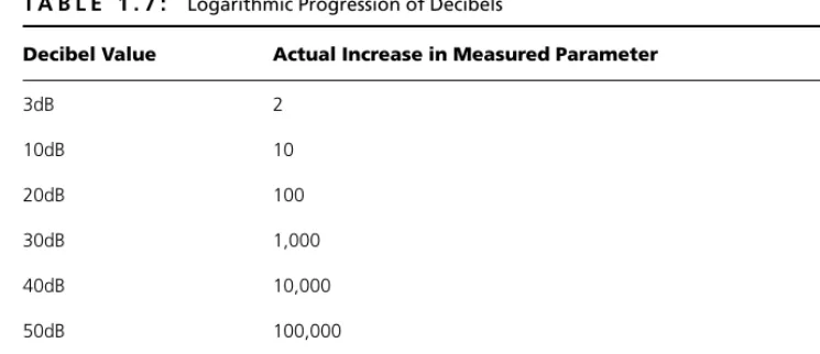
What a Difference a dB Makes! 48
Digging a Little Deeper into Decibels 48
Applying Knowledge of Decibels 52
Speed Bumps: What Slows Down Your Data 52
Hindrances to High-Speed Data Transfer 53
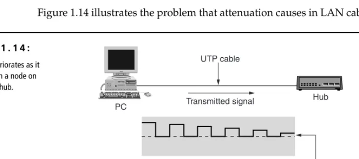
Attenuation (Loss of Signal) 55
Noise (Signal Interference) 57
Equal-Level Far-End Crosstalk (ELFEXT) 60
Pair-to-Pair Crosstalk 61
Power-Sum Crosstalk 62
External Interference 62
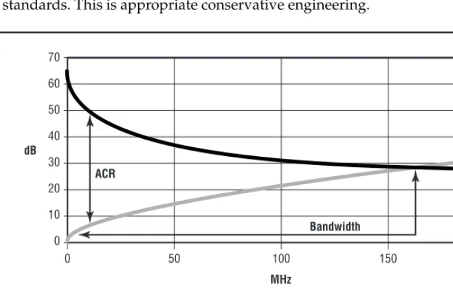
Attenuation-to-Crosstalk Ratio (ACR) 64
Propagation Delay 66
Delay Skew 66
The Future of Cabling Performance 67
2
Cabling Specifications and Standards
69
Structured Cabling and Standardization 70
Standards and Specifying Organizations 73
American National Standards Institute (ANSI) 74
Electronic Industries Alliance (EIA) 75
Telecommunications Industry Association (TIA) 75
Insulated Cable Engineers Association (ICEA) 77
National Fire Protection Association (NFPA) 77
National Electrical Manufacturers Association (NEMA) 78
Federal Communications Commission 78
Underwriters Laboratories (UL) 78
International Organization for Standardizations (ISO) 78
International Electrotechnical Commission (IEC) 79
Institute of Electrical and Electronic Engineers (IEEE) 80 National Institute of Standards and Technology (NIST) 80
International Telecommunications Union (ITU) 80
CSA International (CSA) 81
ATM Forum 82
Lucent SYSTIMAX SCS Cabling System 141
Digital Equipment Corporation DECconnect 141
NORDX/CDT Integrated Building Distribution System 142
3
Choosing the Correct Cabling
143
Topologies 144
Star Topology 145
Bus Topology 146
Ring Topology 147
UTP, Optical Fiber, and Future-Proofing 148
Network Architectures 150
Ethernet 150
10Mbps Ethernet Systems 153
100Mbps Ethernet Systems 159
Gigabit Ethernet (1000Mbps) 162
Token Ring 165
Token Ring and Shielded Twisted Pair (STP) 167
Token Ring and Unshielded Twisted Pair (UTP) 167
Fiber Distributed Data Interface (FDDI) 168
Cabling and FDDI 170
Asynchronous Transfer Mode (ATM) 170
Cabling and ATM 172
100VG-AnyLAN 172
Cable and 100VG-AnyLAN 174
Cascading 175
Network-Connectivity Devices 177
Repeaters 177
Hubs 178
Bridges 181
Switches 185
Routers 185
4
Cable System and Infrastructure Constraints
189
Where Do Codes Come From? 190
The United States Federal Communications Commission 190
The National Fire Protection Association 192
Underwriters Laboratories 194
NEC Chapter 8 Communications Systems 211
Article 800-1—Scope 212
Article 800-6—Mechanical Execution of Work 212
Article 800-7—Hazardous Locations 212
Article 800-10—Overhead Wires and Cables 212
Article 800-11—Underground Circuits Entering Buildings 212 Article 800-30—Circuits Requiring Primary Protectors 213 Article 800-32—Secondary Protector Requirements 214
Article 800-33—Cable Grounding 215
Article 800-40—Primary-Protector Grounding 215
Article 800-50—Listings, Markings, and Installation of
Communications Wires and Cables 216
Article 800-50—Listing Requirements for
Communications Wires and Cables and Communications
Raceways 217
Article 800-52—Installation of Communications Wires,
Cables, and Equipment 218
Knowing and Following the Codes 219
5
Cabling System Components
221
The Cable 222
Horizontal and Backbone Cables 222
Horizontal Cables 223
Backbone Cables 224
Modular Patch Cables 224
Pick the Right Cable for the Job 225
Wall Plates and Connectors 226
Cabling Pathways 227
Conduit 228
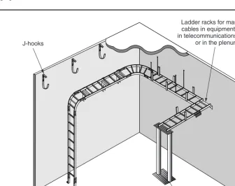
Cable Trays 228
Raceways 230
Fiber-Protection Systems 232
Wiring Closets 233
TIA/EIA Recommendations for Wiring Closets 234
Cabling Racks and Enclosures 236
Wall-Mounted Brackets 237
Full Equipment Cabinets 240
Cable-Management Accessories 241
Electrical Grounding 242
Cross-Connect Devices 242
The 66 Punch-Down Blocks 243
The 110 and S-210 Punch-Down Blocks 244
Modular Patch Panels 245
Consolidation Points 246
Fiber-Optic Connector Panels 247
Administration Standards 248
6
Tools of the Trade
251
Building a Cabling Tool Kit 253
Common Cabling Tools 254
Wire Strippers 254
Coaxial Wire Strippers 255
Fiber-Optic Cable Strippers 257
Wire Cutters 258
Cable Crimpers 259
Twisted-Pair Crimpers 260
Coaxial-Cable Crimpers 262
Punch-Down Tools 263
Fish Tapes 265
Voltage Meter 268
Cable Testing 268
A Cable-Toning Tool 269
Twisted-Pair Continuity Tester 270
Coaxial Tester 271
Optical-Fiber Testers 272
Cabling Supplies and Tools 273
Cable-Pulling Tools 274
Wire-Pulling Lubricant 280
Cable-Marking Supplies 282
Wall-Plate Marking Supplies 283
Tools That a Smart Data-Cable Technician Carries 284
PART II
Network Media and Connectors
7
Copper Cable Media
289
Types of Copper Cabling 290
Major Cable Types Found Today 291
Category 1 UTP Cable 294
Category 2 UTP Cable 295
Category 3 UTP Cable 295
Category 4 UTP Cable 295
Category 5/5e UTP Cable 296
Category 6 UTP Cable 296
Category 7 UTP Cable 296
Shielded Twisted-Pair Cable (IBM Type 1A) 296
Backbone UTP Cable 298
Coaxial Cable 300
Hybrid or Composite Cable 301
Picking the Right Patch Cables 302
Why Pick Copper Cabling? 303
Best Practices for Copper Installation 304
Following Standards 304
Cable Distances 305
Wiring Patterns 307
Planning 308
Cable Management 309
Installing Copper Cable 309
Pulling Cable 310
Separating Voice and Data Patch Panels 312
Sheath Sharing 313
Avoiding Electromagnetic Interference 314
Copper Cable for Data Applications 315
110-Blocks 315
Sample Data Installations 319
Copper Cable for Voice Applications 322
66-Blocks 322
25-Pair Wire Assignments 325
Sample Voice Installations 326
Testing 330
Continuity Testing 331
Wire-Map Testers 331
Cable Certification 332
Common Problems with Copper Cabling 333
Length Problems 333
Wire-Map Problems 333
NEXT and FEXT (Crosstalk) Problems 333
Attenuation Problems 334
8
Wall Plates
335
Wall-Plate Design and Installation Issues 336
Manufacturer System 337
Wall-Plate Location 337
Vertical Position 338
Horizontal Position 339
Wall-Plate Mounting System 340
Outlet Boxes 340
Cut-In Mounting 342
Surface-Mount Outlet Boxes 344
Fixed-Design or Modular Plate 345
Fixed-Design Wall Plates 346
Number of Sockets 347
Types of Sockets 347
Labeling 348
Modular Wall Plates 349
Number of Sockets 349
Wall-Plate Jack Considerations 350
Wall-Plate System Type 351
Cable Connection 351
Jack Orientation 352
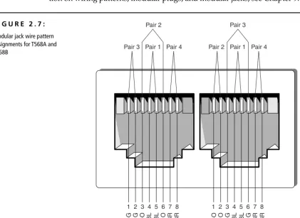
Wiring Pattern 352
Labeling 354
Biscuit Jacks 354
Types of Biscuit Jacks 355
Advantages of Biscuit Jacks 355
9
Connectors
357
Twisted-Pair Cable Connectors 358
Patch-Panel Terminations 358
Solid- versus Stranded-Conductor Cables 359
Modular Jacks and Plugs 360
Wiring Schemes 364
Pins Used by Specific Applications 373
Using a Single Horizontal Cable Run for Two
10Base-T Connections 374
Crossover Cables 375
Shielded Twisted-Pair Connectors 376
Coaxial Cable Connectors 377
F-Series Coaxial Connectors 377
N-Series Coaxial Connectors 378
The BNC Connector 378
Fiber-Optic Cable Connectors 380
Fiber-Optic Connector Types 380
The SFF Issue 382
Installing Fiber-Optic Connectors 384
10
Fiber-Optic Media
387
Introduction to Fiber-Optic Transmission 388
Advantages of Fiber-Optic Cabling 390
Immunity to Electromagnetic Interference (EMI) 390
Higher Possible Data Rates 391
Longer Maximum Distances 391
Better Security 391
Disadvantages of Fiber-Optic Cabling 392
Higher Cost 392
Difficult to Install 392
Types of Fiber-Optic Cables 393
Composition of a Fiber-Optic Cable 394
Optical Fiber 394
Buffer 398
Strength Members 400
Shield Materials 401
Cable Jacket 401
Additional Designations of Fiber-Optic Cables 401
Number of Optical Fibers 405
LAN/WAN Application 406
Fiber Installation Issues 407
Components of a Typical Installation 408
Fiber-Optic Enclosures 408
Fiber-Optic Connectors 410
Fiber-Optic Performance Factors 415
Attenuation 416
Acceptance Angle 417
Numerical Aperture (NA) 417
Modal Dispersion 418
Chromatic Dispersion 419
11
Unbounded (Wireless) Media
421
Infrared Transmissions 422
How Infrared Transmissions Work 423
Point to Point 424
Broadcast 425
Advantages of Infrared 427
Disadvantages of Infrared 428
Examples of Infrared Transmissions 429
IrDA Ports 429
Infrared-Laser Devices 430
Radio-Frequency (RF) Systems 431
How RF Works 431
Low Power, Single Frequency 433
High Power, Single Frequency 434
Spread Spectrum 435
Advantages of RF 437
Disadvantages of RF 437
Examples of RF 438
Microwave Communications 440
How Microwave Communication Works 440
Terrestrial 441
Satellite 443
Advantages of Microwave Communications 444
Disadvantages of Microwave Communications 445
PART III
Cabling Design and Installation
12
Cabling-System Design and Installation
449
Elements of a Successful Cabling Installation 450
Proper Design 450
Desired Standards and Performance Characteristics 451
Flexibility 451
Longevity 452
Ease of Administration 452
Economy 452
Quality Materials 453
Good Workmanship 453
Cabling Topologies 454
Bus Topology 454
The Star Topology 455
The Ring Topology 455
The Mesh Topology 456
Backbones and Segments 457
Understanding the Backbone 457
Understanding Segments 458
Selecting the Right Topology 458
Cabling-Plant Uses 458
Telephone 459
Television 460
Fire-Detection and Security Cabling 461
Choice of Media 461
Telecommunications Closets 462
LAN Wiring 462
Telephone Wiring 464
Power Requirements 466
HVAC Considerations 467
Cabling Management 467
Physical Protection 468
Conduit 468
Cable Trays 469
Standoffs 469
Electrical Protection (Spike Protection) 471
Standby Power Supply (SPS) 471
Uninterruptible Power Supply (UPS) 472
Fire Protection 472
Data and Cabling Security 473
EM (Electromagnetic) Transmission Regulation 474
Tapping Prevention 474
Cabling Installation Procedures 475
Design the Cabling System 475
Schedule the Installation 475
Install the Cabling 476
Cabling Tools 476
Pulling Cable 480
Cabling System Documentation 482
Cable Termination 482
Test the Installation 486
13
Cable-Connector Installation
489
Twisted-Pair Cable-Connector Installation 490
Types of Connectors 490
Conductor Arrangement 492
Connector Crimping Procedures 494
Prerequisites 494
Installing the Connector 495
Testing 500
Coaxial Cable-Connector Installation 500
Types of Connectors 501
Connector Crimping Procedures 502
Prerequisites 502
Installing the Connector 502
Testing 507
Fiber-Optic Cable-Connector Installation 507
Connector Types 508
Connectorizing Methods 508
Epoxy Connectors 509
Epoxyless Connectors 509
Connector Installation Procedures 509
Prerequisites 509
15
Creating a Request for Proposal (RFP)
569
What Is a Request for Proposal? 570
What Do We Want in Life? 571
Developing a Request for Proposal 572
The Needs Analysis 572
Getting Input from Key Players 573
Designing the Project for the RFP 577
Components of a Cabling Infrastructure 577
How Much Is Enough? 581
Rules for Designing Your Infrastructure 583
Writing the RFP 586
Including the Right Content in the RFP 587
What Makes a Good RFP? 588
Distributing the RFP and Managing the Vendor-Selection Process 589
Distributing RFPs to Prospective Vendors 589
Vendor Selection 590
Project Administration 591
Cutover 591
Technology Network Infrastructure Request for Proposal
(A Sample RFP) 592
General 593
Contractor’s Requirements 593
Purpose of This RFP 593
Work Included 594
Intent 595
Cable Plant 595
Horizontal Cable 595
Data Backbone Cabling 597
Fire-Code Compliance 597
Wiring Pathways 597
Wiring Identification 598
Telecommunications Closets 598
MDF/IDF Cable Management 599
As-Built Diagrams 599
Network Hardware Specifications 600
Bidding Process 600
Bid Submittals 600
16
Cabling @ Work: Experience from the Field
601
Hints and Guidelines 602
Know What You Are Doing 602
Plan the Installation 604
Have the Right Equipment 605
Test and Document 605
Train Your Crew 606
Work Safely 606
Make It Pretty 607
Look Good Yourself 608
Plan for Contingencies 608
Match Your Work to the Job 610
Waste Not, Want Not 611
Case Studies 612
A Small Job 612
A Large Job 615
A Peculiar Job 617
An Inside Job 618
Appendices
A
Dictionary of Cabling and Telecommunications
Terms and Concepts
623
B
Cabling Resources
711
Informational Internet Resources 712
wiring.com 712
Engineering Notebook for Communication Cables 712
comp.dcom.cabling 712
The Cabling News Group FAQ 713
Whatis 713
TIA Online 713
TechFest 713
TechEncyclopedia 714
Global Technologies, Inc. 714
Cabletesting.Com 714
National Electrical Code Internet Connection 714
Charles Spurgeon’s Ethernet Web Site 714
Twisted-Pair Ethernet 715
Networking-Hardware Course Notes 715
Directory for WAN, LAN, and ATM Protocols 715
Webopedia: Online Computer Dictionary for Internet Terms
and Technical Support 715
Books, Publications, and Videos 716
Cabling Business Magazine 716
Cabling Installation and Maintenance 716
Cabling Installation and Maintenance Tips and Videos 716
Newton’s Telecom Dictionary by Harry Newton 716
Premises Network Online 717
Building Your Own High-Tech Small Office by Robert Richardson 717 BICSI’s Telecommunications Distribution Methods and Cabling
Installation Manuals 717
Understanding the National Electrical Code (3rd Edition)
by Mike Holt and Charles Michael Holt 717
ANSI/TIA/EIA-568-A Commercial Building Telecommunication
Cabling Standard 717
Vendors and Manufacturers 718
The Siemon Company 718
MilesTek, Inc. 718
IDEAL DataComm 718
Ortronics 719
Superior Essex 719
Jensen Tools 719
Labor Saving Devices, Inc. 719
Avaya (formerly Lucent) SYSTIMAX SCS 719
Erico 719
Berk-Tek 720
Microtest 720
Fluke 720
Amp 720
Panduit 720
Anixter 720
C
Registered Communications and Distribution
Designer (RCDD) Certification
729
Apply and Be Accepted as a Candidate for the Designation of RCDD 723
Maintain Your Accreditation through Continuing Membership
and Education 727
Check Out BICSI and the RCDD Program for Yourself 728
D
Home Cabling: Wiring Your Home for Now
and the Future
729
Home-Cabling Facts and Trends 731
Structured Residential Cabling 732
Picking Cabling Equipment for Home Cabling 735
Thinking Forward 737
E
Overview of IEEE 1394 and USB Networking
739
IEEE 1394 741
USB 744
References 746
F
The Electronics Technicians Association,
International (ETA) Data-Cabling Installer
Certification (DCIC) Program
747
Data-Cabling Installer Certification Program (DCIC) 748
DCIC Categories and Competencies 748
1. 0: Basic Electricity 748
2.0: Data-Communications Basics 748
3.0: Definitions, Symbols, and Abbreviations 749
4.0: Cable Construction 749
5.0: Cable Performance Characteristics 749
6.0: Cabling Standards 749
7.0: Basic Network Topologies 749
8.0: Basic Network Architectures 750
9.0: National Electric Code 750
10.0: Cabling-System Components 750
11.0: DCIC Installation Tools 750
12.0: Connectors and Outlets 751
13.0: Cabling-System Design 751
14.0: Cabling Installation 751
15.0: Connector Installation 751
16.0: Cabling Testing and Certification 751
17.0: Cabling Troubleshooting 751
18.0: Documentation 751
W
elcome to the incredibly complex world of premises data-communications cabling. This introduction will tell you a little about how this book came about and how you can use it to your best advantage.Not only does cabling carry the data across your network, it can also carry voice, serial communications, alarm signals, video, and audio transmissions. In the past, people took their cabling systems for granted. However, over the last few years, the Information Technology world has begun to understand the impor-tance of a reliable and well-designed structured cabling system. The past five years have witnessed an explosion in the number of registered structured-cabling installers. The number of people who need to know the basics of cabling has increased dramatically.
We had a great time writing this book. In the yearlong process of researching, writing, and editing it, we met many consummate professionals in the cabling business. Many distributors, manufacturers, and cabling contractors provided us with feedback, tips, and in-the-field experiences.
During the research phase of the book, we continually reviewed newsgroups, cabling FAQs, and other Internet resources, besides polling Information Technol-ogy managers, help-desk staff, network designers, cable installers, and system managers, to find out what people want to know about their cabling system. The answers we received helped us write this book.
About This Book
This book’s topics run the gamut of cabling; they include the following:
• An introduction to data cabling
• Information on cabling standards and how to choose the correct ones
• Cabling-system components • Tools of the trade
• Copper, fiber-optic, and unbounded media • Wall plates and cable connectors
• Cabling-system design and installation • Cable-connector installation
• Cabling-system testing and troubleshooting • Creating Request for Proposals (RFPs) • Cabling case studies
A cabling dictionary is included at the end of the book so you can look up unfamiliar terms. Five other appendixes include resources for cabling informa-tion, tips on how to get your Registered Communications and Distribution Designer (RCDD) certification, information for the home cabler, a discussion of USB/1394 cabling, and information about ETA’s line of cabling certifications. Finally, a 24-page color insert shows you what various cabling products look like in their “natural environment.”
Who Is This Book For?
If you are standing in your neighborhood bookstore browsing through this book, you may be asking yourself if you should buy it. The procedures in this book are illustrated and written in English rather than “technospeak.” That’s because we, the authors, designed this book specifically to help unlock the mysteries of the wiring closet, cable in the ceiling, wall jacks, and other components of a cabling system. Cabling can be a confusing topic; it has its own language, acronyms, and standards. We designed this book with the following types of people in mind:
• Information Technology (IT) professionals who can use this book to gain a better understanding and appreciation of a structured cabling system
• Do-it-yourselfers who need to install a few new cabling runs in their facility and want to get it right the first time
• New cable installers who want to learn more than just what it takes to pull a cable through the ceiling and terminate it to the patch panel
How to Use This Book
To understand the way this book is put together, you must learn about a few of the special conventions we used. Following are some of the items you will com-monly see.
Italicized words indicate new terms. After each italicized term, you will find a definition.
TIP Tipswill be formatted like this. A tip is a special bit of information that can either
make your work easier or make an installation go more smoothly.
NOTE Notesare formatted like this. When you see a note, it usually indicates some spe-cial circumstance to make note of. Notes often include out-of-the-ordinary infor-mation about working with a telecommunications infrastructure.
WARNING Warningsare found within the text whenever a technical situation arises that may cause damage to a component or cause a system failure of some kind. Addition-ally, warnings are placed in the text to call particular attention to a potentially dan-gerous situation.
Sidebars
This special formatting indicates a sidebar. Sidebarsare entire paragraphs of information that, although related to the topic being discussed, fit better into a standalone discussion. They are just what their name suggests: a sidebar discussion.
Cabling @ Work Sidebars
These special sidebars are used to give real-life examples of situations that actually occurred in the cabling world.
Appendix A is a glossary of the terms used throughout this book. Additionally, a 32-page color insert will show you certain items in color.
Keep an eye out for these special items as you read.
Enjoy!
Cabling
Technology and
Components
■ CHAPTER 1: Introduction to Data Cabling
■ CHAPTER 2: Cabling Standards
■ CHAPTER 3: Choosing the Correct Cabling
■ CHAPTER 4: Cable System and Infrastructure Constraints
■ CHAPTER 5: Cabling System Components
■ CHAPTER 6: Tools of the Trade
Introduction to
Data Cabling
■
The Golden Rules of Data Cabling■
The Importance of Reliable Cabling■
The Legacy of Proprietary Cabling Systems■
Cabling and the Need for Speed■
Cable Design■
Data Communications 101■
Speed Bumps: What Slows Down Your Data“D
ata cabling! It’s just wire. What is there to plan?” the newly promoted programmer-turned-MIS-director commented to Jim. The MIS director had been contracted to help the company move its 750-node network to a new location. During the initial conversation, the director had a couple of other “insights”:• He said that the walls were not even up in the new location, so it was too early to be talking about data cabling.
• To save money, he wanted to pull the old Category 3 cabling and move it to the new location. (“We can run 100Base-TX on the old cable.”)
• He said not to worry about the voice cabling and the cabling for the photo-copier tracking system; someone else would coordinate that.
Jim shouldn’t have been too surprised by the ridiculous nature of these com-ments. Too few people understand the importance of a reliable, standards-based, flexible cabling system. Fewer still understand the challenges of building a high-speed network. Some of the technical problems associated with building a cabling system to support a high-speed network are comprehended only by electrical engineers. And many believe that a separate type of cable should be in the wall for each application (PCs, printers, terminals, copiers, etc.).
Data cabling has come a long way in the past 15 years. This chapter discusses some of the basics of data cabling, including topics such as:
• The golden rules of data cabling • The importance of reliable cabling • The legacy of proprietary cabling systems
• The increasing demands on data cabling to support higher speeds • Cable design and materials used to make cables
• Types of communications media
• Limitations that cabling imposes on higher-speed communications • The future of cabling performance
has its own industry buzzwords, so does the cabling business. In fact, you may hear such an endless stream of buzzwords and foreign terminology that you’ll wish you had majored in electrical engineering in college. But it’s not really that mysterious, and, armed with the background and information we’ll provide, you’ll soon be using cablespeak like a cabling professional.
The Golden Rules of Data Cabling
Listing our own golden rules of data cabling is a great way to start this chapter and the book. If your cabling is not designed and installed properly, you will have problems that you can’t even imagine. From our experience, we’ve become cabling evangelists, spreading the good news of proper cabling. What follows is our list of rules to consider when planning structured-cabling systems:
• Networks never get smaller or less complicated.
• Build one cabling system that will accommodate voice and data.
• Always install more cabling than you currently require. Those extra outlets will come in handy someday.
• Use structured-cabling standards when building a new cabling system. Avoid anything proprietary!
• Quality counts! Use high-quality cabling and cabling components. Cabling is the foundation of your network; if the cabling fails, nothing else will mat-ter. For a given grade or category of cabling, you’ll see a range of pricing, but the highest prices don’t necessarily mean the highest quality. Buy based on the manufacturer’s reputation and proven performance, not the price.
• Don’t scrimp on installation costs. Even quality components and cable must be installed correctly; poor workmanship has trashed more than one cabling installation.
• Plan for higher speed technologies than are commonly available today. Just because 1000Base-T Ethernet seems unnecessary today does not mean it won’t be a requirement in five years.
The Importance of Reliable Cabling
We cannot stress enough the importance of reliable cabling. Two recent studies vindicated our evangelical approach to data cabling. The studies showed:
• Data cabling typically accounts for less than 10 percent of the total cost of the network infrastructure.
• The life span of the typical cabling system is upwards of 16 years. Cabling is likely the second most long-lived asset you have (the first being the shell of the building).
• Nearly 70 percent of all network-related problems are due to poor cabling techniques and cable-component problems.
TIP If you have installed the proper Category or grade of cable, the majority of cabling
problems will usually be related to patch cables, connectors, and termination tech-niques. The permanent portion of the cable (the part in the wall) will not likely be a problem unless it was damaged during installation.
Of course, these were facts that we already knew from our own experiences. We have spent countless hours troubleshooting cabling systems that were non-standard, badly designed, poorly documented, and shoddily installed. We have seen many dollars wasted on the installation of additional cabling and cabling infrastructure support that should have been part of the original installation.
Regardless of how you look at it, cabling is the foundation of your network. It must be reliable!
The Cost of Poor Cabling
The costs that result from poorly planned and poorly implemented cabling sys-tems can be staggering. One company that had recently moved into a new office space used the existing cabling, which was supposed to be Category 5 cable. Almost immediately, 100Mbps Ethernet network users reported intermittent problems.
applications running under Windows 98 and Windows NT were locking up, which often caused them to have to reboot their PC.
After many months of network annoyances, the company finally had the cable runs tested. Many cables did not even meet the minimum requirements of a Cate-gory 5 installation, and other cabling runs were installed and terminated poorly.
WARNING Often, network managers mistakenly assume that data cabling either works or it does not, with no in-between. Cabling cancause intermittent problems.
Is the Cabling to Blame?
Can faulty cabling cause the type of intermittent problems that the aforemen-tioned company experienced? Contrary to popular opinion, it certainly can. In addition to being vulnerable to outside interference from electric motors, fluores-cent lighting, elevators, cellular phones, copiers, and microwave ovens, faulty cabling can lead to intermittent problems for other reasons.
These reasons usually pertain to substandard components (patch panels, con-nectors, and cable) and poor installation techniques, and they can subtly cause dropped or incomplete packets. These lost packets cause the network adapters to have to time-out and retransmit the data.
Robert Metcalfe (inventor of Ethernet, founder of 3Com, columnist for Info-World, industry pundit, and Jim’s hero) helped coin the term drop-rate magnifica-tion. Drop-rate magnification describes the high degree of network problems caused by dropping a few packets. Metcalfe estimates that a 1-percent drop in Ethernet packets can correlate to an 80 percent drop in throughput. Modern net-work protocols that send multiple packets and expect only a single acknowl-edgement (such as TCP/IP and Novell’s IPX/SPX) are especially susceptible to drop-rate magnification, as a single dropped packet may cause an entire stream of packets to be retransmitted.
You’ve Come a Long Way, Baby:
The Legacy of Proprietary Cabling Systems
Early cabling systems were unstructured, proprietary, and often worked only with a specific vendor’s equipment. They were designed and installed for main-frames and were a combination of thicknet cable, twinax cable, and terminal cable (RS-232). Because no cabling standards existed, an MIS director simply had to ask the vendor which cable type should be run for a specific type of host or ter-minal. Frequently, though, vendor-specific cabling caused problems due to lack of flexibility. Unfortunately, the legacy of early cabling still lingers in many places.
PC LANs came on the scene in the mid-1980s; these systems usually consisted of thicknet cable, thinnet cable, or some combination of the two. These cabling systems were also limited to only certain types of hosts and network nodes.
As PC LANs became popular, some companies demonstrated the very extremes of data cabling. Looking back, it’s surprising to think that the ceilings, walls, and floor trenches could hold all the cable necessary to provide connectivity to each system. As one company prepared to install a 1,000-node PC LAN, they were shocked to find all the different types of cabling systems needed. Each system was wired to a different wiring closet or computer room and included the following:
• Wang dual coaxial cable for Wang word-processing terminals • IBM twinax cable for IBM 5250 terminals
• Twisted-pair cable containing one or two pairs, used by the digital phone system
• Thick Ethernet from the DEC VAX to terminal servers
• RS-232 cable to wiring closets connecting to DEC VAX terminal servers • RS-232 cable from certain secretarial workstations to a proprietary NBI
word-processing system
• Coaxial cables connecting a handful of PCs to a single NetWare server
The new LAN was based on a twisted-pair Ethernet system that used unshielded twisted-pair cabling called Synoptics Lattisnet, which was a precursor to the 10Base-T standards. Due to budget considerations, when the LAN cabling was installed, this company often used spare pairs in the existing phone cables. When extra pairs were not available, additional cable was installed. Networking stan-dards such as 10Base-T were but a twinkle in the IEEE’s (Institute of Electrical and Electronic Engineers) eye, and guidelines such as the ANSI/TIA/EIA-568-A Cabling Standard were not yet formulated (see the next section for more informa-tion on TIA/EIA-568-A). Companies deploying twisted-pair LANs had little guidance, to say the least.
Much of the cable that was used at this company was sub–Category 3, meaning that it did not meet the minimum Category 3 performance requirements. Unfor-tunately, because the cabling was not even Category 3, once the 10Base-T specifi-cation was approved, many of the installed cables would not support 10Base-T cards on most of the network. So three years into this company’s network deploy-ments, it had to rewire much of its building.
KEY TERM Application Often, you will see the term application used when referring to cabling. If you are like me, you think of an application as a software program that runs on your computer. However, when discussing cabling infrastructures, an application is the technology that will take advantage of the cabling system. Applications include telephone systems (analog voice and digital voice), Ethernet, Token Ring, ATM, ISDN, and RS-232.
Proprietary Cabling Is a Thing of the Past
The company discussed in the last section had at least seven different types of cables running through the walls, floors, and ceilings. Each cable met only the standards dictated by the vendor that required that particular cable type.
will remember cables often being referred to as Level 1, Level 2, or Level 3 cables. Anixter continues to maintain the Anixter levels program; it is currently called Anixter Levels XP.
The Need for a Comprehensive Standard
Twisted-pair cabling in the late 1980s and early 1990s was often installed to sup-port digital or analog telephone systems. Early twisted-pair cabling (Level 1 or Level 2) often proved marginal or insufficient for supporting the higher frequen-cies and data rates required for network applications such as Ethernet and Token Ring. Even when the cabling did marginally support higher speeds of data trans-fer (10Mbps), the connecting hardware and installation methods were often still stuck in the “voice” age, which meant that connectors, wall plates, and patch panels were designed to support voice applications only.
The Anixter Cables Performance Levels document only described performance standards for cables. A more comprehensive standard had to be developed to out-line not only the types of cables that should be used but also the standards for deployment, connectors, patch panels, and more.
A consortium of telecommunications vendors and consultants worked in con-junction with the American National Standards Institute (ANSI), Electronic Indus-tries Association (EIA), and the Telecommunications Industry Association (TIA) to create a standard originally known as the Commercial Building Telecommuni-cations Cabling Standard or ANSI/EIA/TIA-568-1991. This Standard has been revised and updated several times and is now known as ANSI/TIA/EIA-568-A or just TIA/EIA-568-A; it is discussed at length in Chapter 2. In subsequent years, TIA/EIA-568-A has been updated with a series of addenda. The latest adden-dum, TIA/EIA-568-A-5, covers requirements for enhanced Category 5 (Category 5e). A completely updated version of this standard is currently being authored by a working committee of the TIA and will be released as ANSI/TIA/EIA-568-B.
Cabling and the Need for Speed
already planning technologies that may support data rates of up to 10Gbps, such as 10Gbps ATM and 10Gbps Ethernet.
The average number of nodes on a network segment has decreased dramati-cally, while the number of applications and the size of the data transferred has increased dramatically. Applications are becoming more complex and the amount of network bandwidth required by the typical user is increasing. Is the band-width provided by some of the new ultra-high-speed network applications (such as 1Gb Ethernet) required today? Maybe not, but networks and applications will no doubt require such throughput in the future.
Cabling @ Work:
The Increasing Demands of
Modern Applications
A perfect example of the increasing demands put on networks by applications is a law firm that eight years ago was running typical office-automation software applications on its LAN. The average document worked on was about four pages in length and 12KB in size. This firm also used electronic mail; a typical e-mail size was no more than 500 bytes. Other applications included dBase III and a couple small corresponding databases, a terminal-emulation application that connected to the firm’s IBM minicomputer, and a few Lotus 1-2-3 programs. The size of transferred data files was relatively small, and the average 10Base-T network-segment size was about 100 nodes per segment.
Today, the same law firm is still using its 10Base-T and finding it increasingly insufficient for their ever-growing data processing and office-automation needs. The average docu-ment length is still around four pages, but, thanks to the increasing complexity of modern word-processing software and templates, the average document is nearly 50KB in size!
Even simple e-mail messages have grown in size and complexity. An average, simple e-mail message size is now about 1.5KB, and, with the new message technologies that allow the integration of inbound/outbound faxing, an e-mail message with a six-page fax attached has an average size of 550KB. Further, the firm integrated the voice-mail system with the e-mail system so that inbound voice mail is automatically routed to the user’s mailbox. The average 30-second voice mail message is about 150KB.
The firm also implemented an imaging system that scans and stores many documents that previously would have taken up physical file space. Included in this imaging system are lit-igation support documents, accounting information, and older client documentation. A single-page TIF file can vary in size (depending on the complexity of the image) from 40 to 125KB.
Additional software applications include a client/server document-management system, a client/server accounting system, and several other networked programs that the firm only dreamed about eight years before. Most of the firm’s attorneys make heavy use of the Internet, often visiting sites that provide streaming audio and video.
Today, the firm’s average switched segment size is less than 36 nodes per segment, and the segments are switched to a 100Mbps backbone. Even with these small segment sizes, many segments are congested. Although the firm would like to begin running 100Base-TX Ethernet to the desktop, it is finding that its Category 3 cabling does not support 100Base-TX networking.
When this firm installs its new cabling system to support the next-generation network applications, you can be sure that it will want to choose the cabling infrastructure and network application carefully to ensure that its needs for the next 10 to 15 years will be accommodated.
Does the fact that software applications and data are putting more and more of a demand on the network have anything to do with data cabling? You might think that the issue is more related to network-interface cards, hubs, switches, and routers, but, as data rates increase, the need for higher levels of performance on the cable also increases.
Types of Communications Media
Four major types of communications media (cabling) are available for data net-working today: unshielded twisted pair, shielded twisted pair, coaxial, and fiber optic. An additional variety of twisted-pair cable called screened twisted pair has recently appeared; it is a hybrid of shielded and unshielded twisted pair.
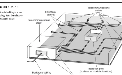
It is important to distinguish between backbone cables and horizontal cables. Backbone cables connect network equipment such as servers, switches, and routers and connect equipment rooms and communication closets. Horizontal cables run from the communication closets to the wall outlets. For new installations, multi-strand fiber-optic cable is essentially universal as backbone cable. For the hori-zontal, UTP reigns supreme. Much of the focus of this book is on UTP cable.
Twisted-Pair Cable
installation is also simpler, and the tools required to install it are not as costly. Unshielded twisted pair (UTP) and shielded twisted pair (STP) are the two pri-mary varieties of twisted pair on the market today, but screened twisted pair (ScTP) is emerging and may become more common.
Unshielded Twisted Pair (UTP) Though it has been used for many years for telephone systems, unshielded twisted pair (UTP) for LANs first became com-mon in the late 1980s with the advent of Ethernet over twisted-pair wiring and the 10Base-T standard. UTP is cost effective and simple to install, and its band-width capabilities are continually being improved.
NOTE An interesting historical note: Alexander Graham Bell invented and patented
twisted-pair cabling and an optical telephone in the 1880s. During that time, Bell offered to sell his company to Western Union for $100,000, but it refused to buy.
UTP cabling typically has only an outer covering (jacket) consisting of some type of nonconducting material. This jacket covers one or more pairs of wire that are twisted together. In this chapter, as well as throughout much of the rest of the book, assume unless specified otherwise that UTP cable is a four-pair cable. Four-pair cable is the most commonly used cable in network installations today. The characteristic impedance of UTP cable is 100 ohms plus or minus 15 percent, though 120-ohm UTP cable is sometimes used in Europe and is allowed by the ISO/IEC 11801 cabling standard.
A typical UTP cable is shown in Figure 1.1. This simple cable consists of a jacket that surrounds four twisted pairs. Each wire is covered by an insulation material with good dielectric properties. For data cables, this means that in addition to being electrically nonconductive, it must also have certain properties that allow good signal propagation.
Not All UTP Is Created Equal!
Though two cables may look identical, their supported data rates can be dramatically dif-ferent. Older UTP cables that were installed to support telephone systems may not even support 10Base-T Ethernet. The ANSI/TIA/EIA-568-A Standard helps consumers choose the right cable (and components) for the right application. The Standard has been updated over the years and contains addenda 1 through 5. It currently defines several cat-egories of UTP cable: Catcat-egories 3, 4, 5, and 5e. Catcat-egories 1 and 2 are de facto defini-tions commonly held by the industry:
Category 1 (not defined by ANSI/EIA/TIA-568-A) This type of cable usually sup-ports frequencies of less than 1MHz. Common applications include analog voice tele-phone systems.
Category 2 (not defined by ANSI/EIA/TIA-568-A) This cable type supports fre-quencies of up to 4MHz. It’s not commonly installed, except in installations that use twisted-pair ArcNet and Apple LocalTalk networks. Its requirements are based on the original, proprietary IBM Cabling System.
Continued on next page UTP
F I G U R E 1 . 1 :
Category 3 This type of cable supports data rates up to 16MHz. The cable was the most common variety of UTP for a number of years starting in the late 1980s. Com-mon applications include 4Mbps UTP Token Ring, 10Base-T Ethernet, 100Base-T4, and digital and analog telephone systems.
Category 4 Cable belonging to Category 4 was designed to support frequencies of up to 20MHz, specifically in response to a need for a UTP solution for 16Mbps Token Ring LANs. It was quickly replaced in the market when Category 5 was devel-oped, as Category 5 gives five times the bandwidth with only a small increment in price.
Category 5 Currently, Category 5 is the most common cable installed, although most new installations use an enhanced version. It is designed to support frequencies of up to 100MHz. Applications include 100Base-TX TP-PMD (FDDI over copper), 155Mbps ATM over UTP, and, thanks to sophisticated encoding techniques, 1000Base-T Ethernet. To support 1000Base-T applications, the installed cabling system must pass performance tests specified by TSB-95 (TSB-95 is a Technical Service Bulletin issued in support of ANSI/TIA/EIA-568-A, which defines additional test parameters.)
Category 5e (enhanced Category 5) Category 5e was introduced with the TIA/EIA-568-A-5 addendum of the cabling standard. Even though it has the same rated bandwidth as Category 5, i.e., 100MHz, additional performance criteria and a tighter transmission test requirement make it more suitable for high-speed applica-tions such as Gigabit Ethernet. Applicaapplica-tions are the same as those for Category 5 cabling.
Other TIA/EIA categories are in development that will support even higher frequencies than 100MHz; among these are Category 6 and Category 7 cabling.
The cabling standards are discussed in more detail in Chapter 2. Additional information on copper media can be found in Chapters 7 and 9.
Some STP cabling, such as IBM Types 1 and 1A cable, uses a woven copper-braided shield, which provides considerable protection against electromagnetic interference (EMI.) Inside the woven copper shield, STP consists of twisted pairs of wire (usually two pairs) wrapped in a foil shield. Some STP cables have only the foil shield around the wire pairs. Figure 1.2 shows a typical STP cable. In the IBM design, the wire used in STP cable is 22 AWG (just a little larger than the 24 AWG wire used by typical UTP LAN cables) and has a nominal impedance of 150 ohms.
Constructions of STP in 24 AWG, identical in copper conductor size to UTP cables, are more commonly used today.
Simply installing STP cabling does not guarantee you will improve a cable’s immunity to EMI or reduce the emissions from the cable. Several critical condi-tions must be met to achieve good shield performance:
• The shield must be electrically continuous along the whole link.
• All components in the link must be shielded. No UTP patch cords can be used. • The shield must full enclose the pair and the overall shield must fully
enclose the core. Any gap in the shield covering is a source of EMI leakage. • The shield must be grounded at both ends of the link, and the building
grounding system must conform to grounding standards (such as TIA/EIA-607).
Individual pair Cable jacket
Pair shield Overall shield
F I G U R E 1 . 2 :
If one of these conditions is not satisfied, shield performance will be badly degraded. For example, tests have shown that if the shield continuity is broken, the emissions from a shielded cabling system increase by 20dB on the average.
Screened Twisted Pair (ScTP) One of the interesting developments over the past few years is screened twisted-pair (ScTP) cabling, a hybrid of STP and UTP cable. ScTP cable contains four pairs of 24 AWG, 100-ohm wire (see Figure 1.3) surrounded by a foil shield or wrapper and a drain wire for bonding purposes. ScTP is also sometimes called foil twisted-pair (FTP) cable because the foil shield surrounds all four conductors. This foil shield is not as large as the woven copper-braided jacket used by some STP cabling systems such as IBM Types 1 and 1A. ScTP cable is essentially STP cabling that does not shield the individual pairs; the shield may also be smaller than some varieties of STP cabling.
The foil shield is the reason ScTP is less susceptible to noise. In order to imple-ment a completely effective ScTP system, however, the shield continuity must be maintained throughout the entire channel—including patch panels, wall plates, and patch cords. Yes, you read this correctly; the continuity of not only the wires but also the shield must be maintained through connections. Like STP cabling, the entire system must be bonded to ground at both ends of each cable run, or you will have created a massive antenna.
Cable jacket Foil shield
or screen
Wire pairs
F I G U R E 1 . 3 :
Standard eight-position modular jacks (commonly called RJ-45s) do not have the ability to insure a proper ground through the cable shield. So special mating hardware, jacks, patch panels, and even tools must be used to install an ScTP cabling system. Many manufacturers of ScTP cable and components exist—just make sure to follow all installation guidelines.
ScTP is recommended for use in environments that have abnormally high ambient electromagnetic interference, such as hospitals, airports, or govern-ment/military communications centers. The value of an ScTP system in relation to its additional cost is sometimes questioned, as some tests indicate that UTP noise immunity and emissions characteristics are comparable with ScTP cabling systems. Often, the decision to use ScTP simply boils down to whether you want the warm and fuzzy feeling of knowing an extra shield is in place.
No standard exists on the use of ScTP, though the TIA is currently working on one. So a number of vendors have introduced their own ScTP products. They are proprietary and often don’t work with other vendor’s components. If you choose an ScTP solution prior to the standards being developed for it, you should use a single vendor’s cable and components.
Should You Choose Unshielded, Shielded, Screened,
or Optical-Fiber Cable for Your Horizontal Wiring?
Many network managers and cabling-infrastructure systems designers face the question of which cabling to choose. Often the decision is very cut and dried, but sometimes it is not.
For typical office environments, UTP cable will be always be the best choice (at least until fiber-network components drop in price). Most offices don’t experience anywhere near the amount of electromagnetic interference necessary to justify the additional expense of installing shielded twisted-pair cabling.
Environments such as hospitals and airports may benefit from a shielded or screened cabling system. The deciding factor seems to be the external field strength. If the external field strength does not exceed three volts per meter (V/m), good-quality UTP cabling should work fine. If the field strength exceeds threeV/m, shielded cable will be a better choice.
However, many cabling designers think that if the field strength exceeds three V/m, fiber-optic cable is a better choice. Further, these designers will point out the additional band-width and security of fiber-optic cable.
Although everyone has an opinion on the type of cable you should install, it is true that the only cable type that won’t be outgrown quickly is optical fiber. Fiber-optic cables are already the media of choice for the backbone. As hubs, routers, and workstation network-interface cards for fiber-optic cables come down in price, fiber will move more quickly in to the horizontal cabling space.
Optical-Fiber Cable
As late as 1993, it seemed that in order to move toward the future of desktop computing, businesses would have to install fiber-optic cabling directly to the desktop. Copper cable (UTP) performance continues to be surprising, however. Fiber-optic cable is discussed in more detail in Chapter 10.
NOTE Fiberversus fibre: Are these the same? Yes, just as color(U.S. spelling) and colour (British spelling) are the same. Your spell checker will probably question your use of fibre, however.
Although, for most of us, fiber to the desktop is not yet a practical reality, fiber-optic cable is touted as the ultimate answer to all our voice, video, and data trans-mission needs and continues to make inroads in the LAN market. Some distinct advantages of fiber-optic cable include:
• Transmission distances can be much greater than with copper cable. • Potential bandwidth is dramatically higher than with copper.
• Fiber optic is not susceptible to outside EMI or crosstalk interference, nor does it generate EMI or crosstalk.
• Fiber-optic cable is much more secure than copper cable because it is extremely difficult to monitor, “eavesdrop,” or tap a fiber cable.
NOTE Fiber-optic cable can easily handle data at speeds above 1Gbps; in fact, it has been
Since the late 1980s, LAN solutions have used fiber-optic cable in some capac-ity. Recently, a number of ingenious solutions that allow both voice and data to use the same fiber-optic cable have emerged.
Fiber Optics Comes of Age (Affordably)
Fiber-optic cable used to be much harder to install than copper cable, requiring precise installation practices. However, in the past few years, the cost of an installed fiber-optic link has dropped and is now often only 10 to 15 percent more than the cost of a UTP link. Better fiber-optic connectors and installation techniques have made fiber-optic systems easier to install. In fact, installers experienced with both fiber-optic systems and copper systems will tell you that with the newest fiber-optic connectors and installation tech-niques, fiber-optic cable is easier to install than UTP.
The main hindrance to using fiber optics all the way to the desktop in lieu of UTP or STP is that the electronics (workstation network-interface cards and hubs) are still significantly more expensive.
Fiber-optic cable uses a strand of glass or plastic to transmit data signals using light; the data is carried in light pulses. Unlike the transmission techniques used by its copper cousins, optical fibers are not electrical in nature.
Plastic-core cable is easier to install and slightly cheaper than glass core, but plastic cannot carry data as far as glass. In addition, graded-index plastic optical fiber (POF) has yet to make a widespread appearance on the market, and the cost-to-bandwidth value proposition for POF is poor and may doom it to obscurity.
NOTE Light is transmitted through a fiber-optic cable by light-emitting diodes (LEDs) or
lasers. With newer LAN equipment designed to operate over longer distances, such as with 1000Base-LX, lasers are commonly being used.
material, and, finally, a jacket. The cladding provides a lower refractive index to cause reflection within the core so that light waves can be transmitted through the fiber.
Two varieties of fiber-optic cable are commonly used in LANs and WANs today: single-mode and multimode. The mode can be thought of as bundles of light rays entering the fiber; these light rays enter at certain angles.
KEY TERM Dark Fiber No, dark fiberis not a special, new type of fiber cable. When telecommunications companies and private businesses run fiber-optic cable, they never run the exact number of strands of fiber they need. That would be foolish. Instead, they run two or three times the amount of fiber they require. The spare strands of fiber are often called dark fiberbecause they are not then in use, i.e., they don’t have light passing through them. Telecommunications companies often lease out these extra strands to other companies.
Single-Mode Fiber-Optic Cable Single-mode fiber (SMF, sometimes called monomode) optic cable is most commonly used by telephone companies and in data installations as backbone cable. Single-mode fiber-optic cable is not used as horizontal cable to connect computers to hubs. The light in a single-mode cable travels straight down the fiber (as shown in Figure 1.5) and does not bounce off the surrounding cladding as it travels. Typical single-mode wavelengths are 1,310 and 1,550 nanometers.
Outer jacket
Fiber core
Cladding
Protective buffer or coating
Dielectric strengthening
material
F I G U R E 1 . 4 :
Before you install single-mode fiber-optic cable, make sure the equipment you are using supports it. The equipment that uses single-mode fiber typically uses lasers to transmit light through the cable because a laser is the only light source capable of inserting light into the very small (8 to 10 micron) core of a single-mode fiber.
Multimode Fiber-Optic Cable Multimode fiber (MMF) optic cable is usually the fiber-optic cable used with networking applications such as 10Base-FL, 100Base-F, FDDI, ATM, and others that require fiber optics for both horizontal and backbone cable. Multimode cable allows more than one mode of light to propagate through the cable. Typical wavelengths of light used in multimode cable are 850 and 1,300 nanometers.
There are two types of multimode fiber-optic cable: step index or graded index. Step-index multimode fiber-optic cable indicates that the refractive index between the core and the cladding is very distinctive. The graded-index fiber-optic cable is the most common type of multimode fiber. The core of a graded-index fiber contains many layers of glass; each has a lower graded-index of refraction going outward from the core of the fiber. Both types of multimode fiber permit multiple modes of light to travel through the fiber simultaneously (see Fig-ure 1.6). Graded-index fiber is preferred because less light is lost as the signal travels around bends in the cable.
The typical multimode fiber-optic cable used for horizontal cabling consists of two strands of fiber (duplex); the core is 62.5 microns (micrometers) in diameter, and the cladding is 125 microns in diameter (the measurement is often simply referred to as 62.5/125-micron). The newest version of the ANSI/TIA/EIA-568-B Standard also recognizes the use of 50/125-micron multimode fiber-optic cable.
Light source
Light ray
Cladding
Core
F I G U R E 1 . 5 :
Coaxial Cable
At one time, coaxial cable was the most widely used cable type in the networking business. However, it is falling by the wayside in the data-networking arena, except for those lucky enough to have cable-modem Internet service. Coaxial (or just coax) cable is difficult to run and is generally more expensive than twisted-pair cable. In defense of coaxial cable, however, it provides a tremendous amount of bandwidth and is not as susceptible to outside interference as is UTP. Overall installation costs might also be lower than for other cable types because the con-nectors take less time to apply. Although we commonly use it to connect our tele-visions to our VCRs, we will probably soon see fiber-optic or twisted-pair interfaces to televisions and VCRs.
Coaxial cable comes in many different flavors, but the basic design is the same for all types. Figure 1.7 shows a typical coaxial cable; at the center is a solid (or sometimes stranded) copper core. Some type of insulation material, such as TFE or PVC, surrounds the core. Either a sleeve or braided-wire mesh shields the insulation, and a jacket covers the entire cable.
The shielding shown in Figure 1.7 protects the data transmitted through the core from outside electrical noise and keeps the data from generating significant amounts of interference. Coaxial cable works well in environments where high amounts of interference are common. For example, some years ago, Jim installed coaxial cable in a power plant because in some areas the Category 3 cable was not reliable.
Light source
Different modes of light existing
Cladding
Core
F I G U R E 1 . 6 :
A number of varieties of coaxial cable are available on the market. You pick the coaxial cable required for the application; unfortunately, coaxial cable installed for Ethernet cannot be used for an application such an ArcNet. Some common types of coaxial cable are listed in Table 1.1.
T A B L E 1 . 1 : Common Coaxial-Cable Types
Cable Description
RG-58 /U A 50-ohm coaxial cable with a solid core. Commonly called thinnet and used with 10Base-2 Ethernet and some cable-TV applications.
RG-58 A/U A 50-ohm coaxial cable with a stranded core. Also known as thinnet. Used by 10Base-2 Ethernet and some cable-TV applications.
RG-58 C/U A military-specification version of RG-58 A/U.
RG-59U A 75-ohm coaxial cable. Used with Wang systems and some cable-TV applications. RG-6U A 75-ohm coaxial cable. The current minimum grade to install in residences because
it will handle the full frequency range of satellite service, plus high-definition TV and cable-modem service.
RG-6 Quad Shield Same as RG-6U, but with additional shielding for enhanced noise immunity. Cur-rently the recommended cable to use in residences.
RG-62U A 93-ohm coaxial cable. Used with IBM cabling systems and ArcNet.
Insulation (PVC or teflon)
Shielding (copper wire mesh or aluminum sleeve) Conducting core
Cable jacket
F I G U R E 1 . 7 :
Plenum Cables: Debunking the Myths
It’s time to set the record straight about several commonly held, but incorrect, beliefs about plenum-rated cable. These misconceptions get in the way of most discussions about LAN cabling, but are especially bothersome in relation to UTP.
Myth #1: Any false