Survey of Discrete Hartley Transform using
Different Types of Method
Sonali Singh, Dr. Manish Jain
M. Tech Scholar, Dept. of Electronics and Communication, RKDF Institute of Science & Technology, Bhopal, India
Associate Professor, Dept. of Electronics and Communication, RKDF Institute of Science & Technology, Bhopal, India
ABSTRACT: A discrete Hartley transform (DHT) algorithm can be efficiently implemented on a highly modular and parallel architecture having a regular structure is consisting of multiplier and adder. Discrete Hartley Transform (DHT) is one of the transform used for converting data in time domain into frequency domain using only real values. Many technologies have been investigated so far to reduce delay and area of the DHT system. This paper presents a comprehensive review of maximum combinational path delay (MCPD) and number of slice count of discrete Hartley transform.
KEYWORDS:Discrete Hartley Transform (DHT), Urdhwa Multiplier, MCPD, and Number of slice
I. INTRODUCTION
Digital signal processing (DSP) includes processing of data in various domains based on their applications.DSP has vast applications in various fields such as space, medical, commercial, industrial and scientific [1]. Each requires processing of vast data for collecting useful information. Transform is a technique used in DSP for converting one form of data in another. A family of transform is available in DSP for data processing .Fourier analysis one of the oldest technique used in this family [2]. Fourier analysis is named after Jean baptiste joseph Fourier (1768-1830) a French mathematician and physicist. It was used for periodic continuous signals. Fourier series is a technique which decomposes a signal in time domain into a no. of sine and cosine waves in frequency domain. But it was not applicable for non-periodic signals. Then came Fourier transform into existence which removes the drawback of Fourier series and thus can be used for non-periodic continuous signals [3]. Fourier transform is a mathematical tool using integrals. But Fourier transform is not suitable for non-stationary signals. Since both transforms are not applicable for discrete signals, so there is a need for new transform for discrete signals. Discrete time Fourier transform (DTFT) is used for signals that extend from positive to negative infinity but are not periodic. DTFT is not used for periodic discrete signals so discrete Fourier transform (DFT) can into existence. DFT is a discrete numerical equivalent of FT using summation instead of integrals. DFT is used for signals that repeat themselves in periodic fashion extending from positive to negative infinity. FFT is improvement of DFT in which computation has becomes faster [4].
All the family members of Fourier till now works on complex values which requires large storage space and computationally complex in nature. So, now comes a new member of transform called Discrete Hartley transform (DHT) which converts real values into real values. Therefore, it needs lesser storage space and less computational complexity.
Techniques based on Discrete Cosine Transform [7], Hadamard Transform [8], Wavelet Transform [9], Principal Component Analysis [10] etc have also been subject of studies.
The paper is organized as follows: Section II presents the discrete Hartley transform System Model, section III presents the Challenges and issues, section IV presents Literature review, Results and discussions are provided in Section V. Finally, in section VI conclusions are summarized.
II. DISCRETE HARTLEY TRANSFORM
Discrete Hartley Transform is abbreviated for DHT and this transform was proposed by R. V. L. Hartley in 1942. DHT is the analogous to Fast Fourier transform which provides the only real value at any cost. The main difference from the DFT is that it transforms the real inputs to real outputs with no intrinsic involvement of complex value. DFT can be used to compute the DHT, and vice versa.
In other words, Discrete Hartley transform is used to convert real values into real ones. It requires decomposition of data into stages using butterfly similar to FFT. But the butterfly used in DHT is quite different in terms of coefficients or multipliers. With the increase in number of DHT sequence length the number of coefficients is also increased simultaneously.
Let
N
4
be a power of two. For any real input sequence{
x
(
i
)
:
i
0
,
1
,
2
,...
...
N
1
}
X
(
k
)
DHT
(
N
){
x
((
i
)}
1 01
...
1
,
0
]
/
2
[
).
(
N iN
k
for
N
ki
cas
i
x
Where
cas
(
x
)
cos(
x
)
sin(
x
)
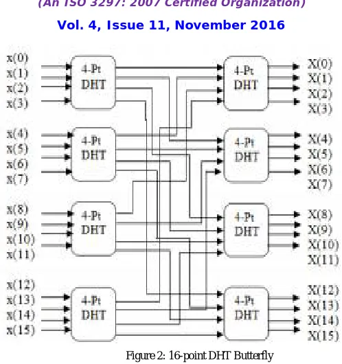
ALGORITHM FOR 16 POINT DHT-
We present an implementation of fast DHT algorithm for a length N=1. There are six stages required to complete the butterfly design of N=16 length DHT. These stages include summing stages and coefficient multiplying stages. Before first stage the data sequence are arranged in bit reversed pattern by using any method like permutation. Then in the first stage the pairs of bit reversed patterns are added to form eight terms. In the second stage, one third of the terms are again added and subtracted to form further three terms.
First two stages do not include any multiplication. Remaining terms are multiplied by the first coefficient. In the next stage again two new coefficients are introduced which is multiplied by the lower half of the third stage. In each stage multiplying of coefficients stage precedes its summing stage. After coefficient multiplication it is preceded by its summing stage to form the common terms used in the final stage. Last stage includes only summing of terms. Finally we get the transformed data sequence in order and do not need any permutation.
DHT
Real Inputs Real Outputs
III. LITERATURE REVIEW
Shirali Parsai et al. [1], Discrete Hartley Transform (DHT) is one of the transform used for converting data in time
domain into frequency domain using only real values. DHT can be used for highly modular and parallel processing of data in VLSI applications. We have proposed a new algorithm for calculating DHT of length 2N, where N=3 and 4.We have implemented multiplier as an improvement in place of simple multiplication used in conventional DHT. This paper gives a comparison between conventional DHT algorithm and proposed DHT algorithm in terms of delays and area.
A. N. Skodras et al. [2], Efficient algorithms have been developed over the past 30 years for computing the forward
and inverse discrete Hartley transforms (DHTs). These are similar to the fast Fourier transform (FFT) algorithms for computing the discrete Fourier transform (DFT). Most of these methods seek to minimise the complexity of computations and/ or the number of operations. A new approach for the computation of the radix-2 fast Hartley transform (FHT) is presented. The proposed algorithm, based on a two-band decomposition of the input data, possesses a very regular structure, avoids the input or out data shuffling, requires slightly less multiplications than the existing
approaches, but increases the number of additions.
Wen-Liang Hsue et al. [3], Real transforms require less complexity for computations and less memory for storages
than complex transforms. However, discrete fractional Fourier and Hartley transforms are complex transforms. In this paper, we propose reality-preserving fractional versions of the discrete Fourier, Hartley, generalized Fourier, and generalized Hartley transforms. All of the proposed real discrete fractional transforms have as many as parameters and thus are very flexible. The proposed real discrete fractional transforms have random eigenvectors and they have only
two distinct eigenvalues 1 and 1. Properties and relationships of the proposed real discrete fractional transforms are investigated. Besides, for the real conventional discrete Hartley and generalized discrete Hartley transforms, we propose their alternative reality-preserving fractionalizations based on diagonal-like matrices to further increase their
flexibility. The proposed real transforms have all of the required good properties to be discrete fractional transforms. Finally, since the proposed new transforms have random outputs and many parameters, they are all suitable for data security applications such as image encryption and watermarking.
Vikramkumar Pudi et al. [4], in this brief, we consider quantum-dot cellular automata (QCA) realization of the
discrete Hadamard transform (DHT). An analysis of a full-parallel solution based on efficient multi bit addition in QCA is first presented. We show that this leads to large area as well as delay. We then propose a bit-serial pipelined architecture for QCA-based DHT. The proposed architecture is based on a new one-bit adder–sub-tractor requiring only six majority gates and a feedback latch that requires only one majority gate and limited wiring. The approach leads to a
reduction in area-delay-cycle product of 74% and 91% (over a full-parallel solution) for word lengths of 4 and 8, respectively. Results of simulations in QCA Designer are also presented.
Doru Florin Chiper et al. [5], a new very large scale integration (VLSI) algorithm for a 2N-length discrete Hartley
transform (DHT) that can be efficiently implemented on a highly modular and parallel VLSI architecture having a
regular structure is presented. The DHT algorithm can be efficiently split on several parallel parts that can be executed
concurrently. Moreover, the proposed algorithm is well suited for the sub expression sharing techniques that can be used to significantly reduce the hardware complexity of the highly parallel VLSI implementation. Using the advantages
of the proposed algorithm and the fact that we can efficiently share the multipliers with the same constant, the number
of the multipliers has been significantly reduced such that the number of multipliers is very small comparing with that
of the existing algorithms. Or ever, the multipliers with a constant can be efficiently implemented in VLSI.
Table 1: Summary of Literature Review
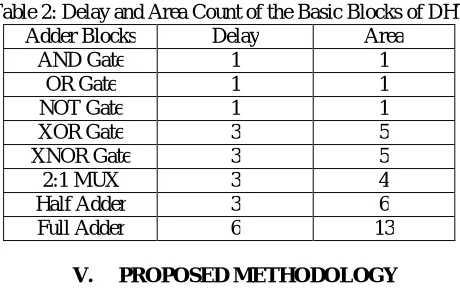
IV. DELAY AND AREA COUNT
The delay and area (cost) evaluation methodology considers all logic gates is consist of AND, OR, and Inverter (AOI), each having delay equal to 1 unit and area equal to 1 unit. The delay evaluation methodology adds up the number of gates in the longest path of a logic block that contributes to the maximum delay. The area evaluation is done by counting the total number of AOI gates required for each logic block.
Table 2: Delay and Area Count of the Basic Blocks of DHT
Adder Blocks Delay Area
AND Gate 1 1
OR Gate 1 1
NOT Gate 1 1
XOR Gate 3 5
XNOR Gate 3 5
2:1 MUX 3 4
Half Adder 3 6
Full Adder 6 13
V. PROPOSED METHODOLOGY
The multiplication of two numbers is done by using Urdhwa Triyakbhyam. Here first the least significant bits of the two digits are multiplied. Then the intermediate digits are cross multi-plied and added together. After this the most significant digits are multiplied. For the 16X16 bit multiplication small block of 2X2 or 4X4 or 8X8 multiplier were used in parallel to make the process easy and efficient.
In our proposed method the high speed carry select adder is replaced by the carry select adder along with Kogge Stone (KS) adder which claims to provide a better speed and less propagation delay. Here we have used four multiplier of 8 bit to perform 16 bit multiplication. The method used is the addition of all partial product formed by the cross multiplication of one bit with another. The LSB bits of first multiplier P1 (7-0) gives the LSB bits Q (7-0) of the final output. Another bits of first multiplier P1 (15-8) are added in series with LSB 8 bits of second multiplier to form the 16 bits, which in turn get added with 16 bits of third multiplier by using KS Adder. The LSB bits of the output of KS adder forms the Q (15-8) bits of the final output. The remaining 8 bit P2(15-8) is then added with the left 8 bits of KS output
Parameter Doru et
al. [5]
Wen-Liang Hsue et al. [3]
Shirali et al. [1]
No. of Slices 398 350 317
No. of 4 input LUTs 684 617 593
No. of bounded IOBs 256 256 256
Maximum combinational path delay(in ns)
39.931 ns
to from 16 bits, which is then added with 16 bits of the fourth multiplier by using KS 2 adder. The output from KS 2 adder forms the Q (31-16) bits. This is how the 32bit output is achieved in the less possible time.
Kogge Stone Adder:-
The main object of this paper is to reduce the route delay and logic delay. As soon as we increase the bit for addition in kogge stone adder area will be increased. So, area and propagation delay can be reduced by the aid of modified KS adder. This adder will be designed like as ripple carry adder. Carry output of one KS adder is connected with another KS adder but this method is very beneficiary for high efficient digital devices as per concerning propagation delay.
Generally, 2 bit KS adder is comprised with two half adder, two AND gate, one XOR gate and one OR gate.
VI. CONCLUSION
DHT is a new transform used for real value to real value conversion. Vedic multiplier is an ancient technique for multiplication. DHT is used in various fields such as image processing, space science, scientific applications etc. Delay provided and area required by hardware are the two key factors which are need to be consider. Here we present DHT with 8×8 Vedic multiplier using Kogge stone adder. The effect of delay and area using DHT are also discussed in thesis work.
REFRENCES
[1] Shirali Parsai and Swapnil Jain, “VHDL Implementation of Discrete Hartley Transform Using Urdhwa Multiplier”, 978-1-4673-9542-7/15/$31.00 ©2015 IEEE.
Figure 3: Logic Diagram of Vedic Multiplier using Kogge Stone Adder
Cout S1 S0
Cin
HA1 HA0
AND AND
XOR
OR
[2] A.N. Skodras, M.F. Aburdene and A.K. Nandi, “Two-band fast Hartley transform”, Electronics Letters 8th January 2015 Vol. 51 No. 1 pp. 57– 59.
[3] Wen-Liang Hsue and Wei-Ching Chang, “Real Discrete Fractional Fourier, Hartley, Generalized Fourier and Generalized Hartley Transforms With Many Parameters”, IEEE Transactions on Circuits and Systems—I: Regular papers, Vol.62, No.10, October 2015.
[4] Vikram kumar Pudi and K. Sridharan, “A Bit-Serial Pipelined Architecture for High-Performance DHT Computation in Quantum-Dot Cellular Automata”, IEEE Transactions on Very Large Scale Integration (VLSI) Systems, IEEE 2014.
[5] Doru Florin Chiper, Senior Member, IEEE, “A Novel VLSI DHT Algorithm for a Highly Modular and Parallel Architecture”, IEEE TRANSACTIONS ON CIRCUITS AND SYSTEMS—II: EXPRESS BRIEFS, VOL. 60, NO. 5, MAY 2013.
[6] Sushma R. Huddar and Sudhir Rao, Kalpana M., “Novel High Speed Vedic Mathematics Multiplier using Compressors”, 978-1 - 4673-5090-7/13/$31.00 ©2013 IEEE.
[7] Jagadguru Swami Sri Bharati Krishna Tirthaji Maharaja, “Vedic Mathematics: Sixteen simple Mathematical Formulae from the Veda”, Delhi (2011).
[8] S. Bouguezel, M. O. Ahmad, and M. N. S. Swamy, “New parametric discrete Fourier and Hartley transforms, and algorithms for fast computation,” IEEE Trans. Circuits Syst. I, Reg. Papers, vol. 58, no. 3, pp. 562–575, Mar. 2011.