IJEDR1502196
International Journal of Engineering Development and Research (www.ijedr.org)1184
Implementation of ANC System Using Xilinx System
Generator (Co-hardware Simulation using Vertex 6
FPGA Kit)
1
Sakshi Gaur,
2Sangeeta Sharma,
3Dr. V.K Gupta
1M.Tech (VLSI Design),2M.Tech (VLSI Design),3Professor (Electronics) 1Electronics and Communication,
1Inderprastha Engineering College, Ghaziabad, U.P India
________________________________________________________________________________________________________ Abstract - Noise is a never ending problem, especially in communication where it corrupts the information bearing signal (desired signal). So recovery of desired signal from a noisy signal is a must. Earlier noise minimization was done using Passive noise control system but it was found inefficient at low frequency noise. For low frequency, Active Noise Cancellation (ANC) system is recently more widely adopted for noise minimization or elimination. Hence, in this paper Active Noise Cancellation system has been realized using Xilinx system generator (Processor simulation and Co-hardware simulation using Vertex 6 FPGA Kit, ML605 board) to implement Least mean square (LMS) algorithm, Feed-forward Filtered-X least mean square (FxLMS) algorithm, Feedback Filtered-X least mean square algorithm. During the flow, VHDL codes for the algorithms are also generated, hence design summary, device utility, RTL view and simulation results are also added here. Finally, the comparison between algorithms are done based on certain parameters like mean square error (MSE), time complexity, convergence rate, noise rejection ratio (NRR), hardware requirements etc.
IndexTerms - ANC, LMS, Feed-forward FxLMS, Feedback FxLMS, Vertex 6 FPGA Kit, ML605 Board, VHDL codes, MSE, NRR, Time, Convergence rate.
______________________________________________________________________________________________________
I.INTRODUCTION
Previously, noise minimization or elimination was done using Passive noise control system but it was found that at low frequency it becomes bulky and expensive. Hence Active Noise Cancellation system (ANC), more recently used after 1970’s, plays an important role in generating recovered signal from a noisy signal and is efficient at low frequency (it is small, compact and less expensive). Active Noise Cancellation system can be implemented in time domain, frequency domain, lattice predictor, sub band etc. Here ANC has been implemented in time domain using algorithms like LMS (least mean square), Feed-forward FxLMS (Filtered-X LMS) and Feedback FxLMS.
LMS Algorithm
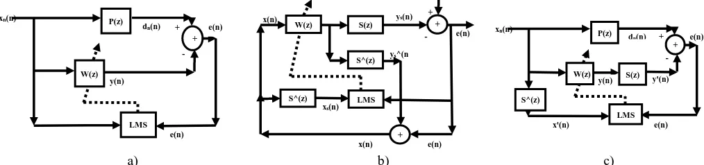
LMS algorithm (Refer Fig. 1a) [1]) is a FIR (Finite impulse response) filter whose weights are continuously updated using weight equation. As per Fig.1a), xn is a noise source, dn is a noisy signal after passing through an unknown plant P(z), W(z) is a
FIR filter whose weights are updated using LMS algorithm and e(n) is a recovered signal [1] [2].
FxLMS Algorithms
It is a LMS algorithm including secondary path (S(z) and S^(z) is a replica of S(z)) effects. When ANC system is implemented practically then various electronic devices are used like microphone, speaker, digital filters, analog to digital (ADC), digital to analog (DAC) etc. Hence, effects of these devices cannot be ignored and sum of the effects of these devices is called as secondary path effects. Secondary path can be estimated offline (estimating secondary path before ANC operation) or online (secondary path is estimated simultaneously along with ANC operation). There are two basic architectures of FxLMS, these are: Feed-forward FxLMS (Refer Fig. 1b) [1]), such a structure needs noise source xn(n) and noisy signal dn(n)) and Feedback FxLMS (Refer Fig.
1c) [1]), such a system needs only noisy signal dn(n) as input.) [1]-[4].
a) b) c)
Figure 1: ANC implementation using a) LMS algorithm b) Feed-forward FxLMS algorithm c) Feedback FxLMS algorithm.
xn(n)
e(n) - + dn(n)
y(n)
+ e(n)
W(z)
LMS
P(z) x(n)
e(n) ys(n)
ys^(n )
x(n) e(n) xs(n)
dn(n)
- +
+
W(z) S(z)
S^(z)
+
S^(z) LMS
dn(n)
- e(n) y'(n) + + e(n) W(z) LMS S(z) S^(z) xn(n)
x'(n) P(z)
IJEDR1502196
International Journal of Engineering Development and Research (www.ijedr.org)1185
II.EXPERIMENTAL SETUP AND SIMULATION RESULTS
This section is divided into three subparts. Experimental setup 1 includes implementing Simulink block diagram for implementing ANC system using LMS (Refer Fig. 2 to Fig. 5) [5] [6]. This Simulink models consists of subsystem, these are FIR filter, noisy signal and LMS adaptive algorithm. Secondary path has been estimated offline, by playing a white noise of length 44100 samples using laptop and recording it. Using these signals, S(z) filter is constructed with convergence rate 0.001 and then it is used in experiment 2 and 3. Therefore S(z) is a 6 order FIR filter with fixed coefficients: 1.2961, 0.9052, 0.3482, 0.1017, 1.8010 and 0.5469. Experimental setup 2 includes implementing Simulink block diagram for implementing ANC system using Feed-forward FxLMS. Experimental setup 3 includes implementing Simulink block diagram for implementing ANC system using Feedback FxLMS. Results have been generated for corresponding experimental setup’s, listed below [7]-[15].
Figure 2 Simulink model for implementing LMS algorithm [6].
Figure 3 Detailing of FIR filter subsystem [6].
Figure 4 Detailing of noisy signal subsystem.
IJEDR1502196
International Journal of Engineering Development and Research (www.ijedr.org)1186
Simulation results 1
Processor Simulation, signals xn, ds, dn, e (xn is noise used in Simulink model, ds is clean signal, dn is a noisy signal, e is
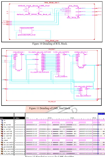
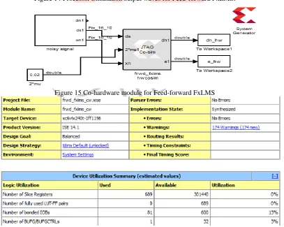
recovered signal) are generated (Refer Fig. 6). Once Processor Simulation is done, Co-hardware simulation module is generated (Refer Fig. 7) and then Co-hardware Simulation is done using FPGA kit (Vertex 6) (ML605 board) (Refer Fig. 8) and output waves (dn_hw, err_hw and xn_hw which are noisy signal, recovered signal and noise signal respectively) are generated and stored in workspace (same as Fig. 6). During Co-hardware Simulation, VHDL code for this algorithm is also generated. Hence, design summary, device utility (Fig. 9), RTL view (Fig. 10 to Fig. 11), VHDL simulation waves (Fig. 12) are also added.
Figure 6 Output waves for LMS generated during Processor Simulation.
Figure 7 Co-hardware module for LMS.
Figure 8 Setup for Co-hardware Simulation using ML605 Board.
IJEDR1502196
International Journal of Engineering Development and Research (www.ijedr.org)1187
Figure 10 Detailing of RTL block.Figure 11 Detailing of LMS_final block.
Figure 12 Simulation waves for LMS algorithm.
Simulation results 2
Upon Processor Simulation, signals xn, ds, dn, e (xn is noise used in Simulink model, ds is clean signal, dn is a noisy signal, e is
IJEDR1502196
International Journal of Engineering Development and Research (www.ijedr.org)1188
Figure 13 Simulink model for implementing Feed-forward FxLMS [6].Figure 14 Processor Simulation output waves for Feed-forward FxLMS.
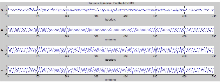
Figure 15 Co-hardware module for Feed-forward FxLMS
IJEDR1502196
International Journal of Engineering Development and Research (www.ijedr.org)1189
Figure 17 Detailing of RTL block of Feed-forward FxLMS (frwd_fxlms).Figure 18 HDL output waves for Feed-forward FxLMS algorithm.
Simulation results 3
Upon Processor Simulation, signals xn, ds, dn, e (xn is noise used in Simulink model, ds is clean signal, dn is a noisy signal, e is
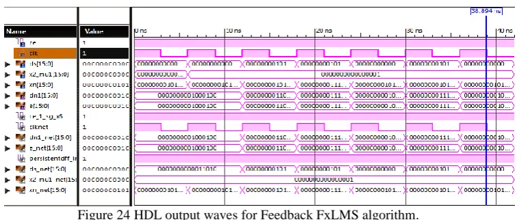
recovered signal) are generated (Refer Fig. 19 and Fig. 20). Once Processor Simulation is done, Co-hardware simulation module is generated and then Co-hardware Simulation is done using FPGA kit (Vertex 6) (ML605 board) (Refer Fig. 21) and output waves (dn_hw, err_hw and xn_hw which are noisy signal, recovered signal and noise signal respectively) are generated and stored in workspace. During Co-hardware Simulation, VHDL code for this algorithm is also generated. Hence, design summary, device utility (Fig. 22), RTL view (Fig. 23), VHDL simulation waves (Fig. 24) are also added.
IJEDR1502196
International Journal of Engineering Development and Research (www.ijedr.org)1190
Figure 20 Processor Simulation output waves for Feedback FxLMS algorithm.Figure 21 Co-hardware module for Feedback algorithm.
Figure 22 Device summary and device utility for Feedback FxLMS algorithm.
IJEDR1502196
International Journal of Engineering Development and Research (www.ijedr.org)1191
Figure 24 HDL output waves for Feedback FxLMS algorithm.III.COMPARATIVE ANALYSIS
The comparative analysis of LMS, Feed-forward FxLMS and Feedback FxLMS (Experimental set up 1, 2 and 3) is done based on certain parameters, listed in Table 1.
Table 1 Comparative Analysis of algorithms based on performance parameters.
S.no Parameters LMS Feed-forward
FxLMS
Feedback FxLMS
1 MSE 0.0291 0.0636 0.0971
2 CRmean(dB) -22.0123 -17.4343 -15.6847
3 NRR(dB) 13.2513 9.8511 8.0181
4 Convergence Rate 0.11 0.02 0.0001
5 Hardware Requirements High higher Highest
6 Time (Processor Simulation + Co-hardware Simulation) (sec)
900 + 39.5 1080 + 40.09 1380+41.85
IV. CONCLUSION
When ANC system is implemented using Xilinx System Generator, it is found (Processor Simulation and Co-hardware Simulation using FPGA kit, Vertex6, ML605 board) that recovered signal generated using Feed-forward FxLMS is better than recovered signal generated using Feedback FxLMS (based on parameters like mean square error, noise rejection ratio). Feed-forward FxLMS converges faster than Feedbck FxLMS and also time taken to simulate Feed-Feed-forward FxLMS is less when compared with Feedback FxLMS.
REFERENCES
[1] Sen M. Kuo, and Dennis R. Morgan, “Active Noise Control: A Tutorial Review,” Proceeding of IEEE, vol. 87, no. 6, 1999, pp. 943-971.
[2] Naitik Nakrani, and Niteen Patel, “Feed-forward and Feedback Active Noise Control System using FxLMS algorithm for Narrowband and Broadband Noise,” Proc. Of International Conference on Communication Systems and Network Technologies, 2012, pp. 577-580.
[3] Iman Ardekani and Waleed Abdulla, “Active Noise Control: Fundamentals and Recent Advances”, Proc. Of Asia Pacific Signal and Information Processing Annual Summit and Conference, Tutorial Session, Taiwan, 2013.
[4] Ali H. Sayed, Fundamentals of Adaptive filtering, Wiley NY, 2003.
[5] Xilinx, ML605 Hardware User Guide, datasheet UG534 (v1.8), October 2012.
[6] http://www.xilinx.com/univ/teaching_materials/dsp_primer/sample/workbook/Xilinx_DSP_workbook_adaptive.pdf.
[7] Dr. Wagdy H Mahmoud, and Dr. Nian Zhang, “Software/Hardware Active noise cancellation system,” Proc. Of ASEE Annual Conference and Exposition, 2013, pp. 112-119.
[8] Ahmed Elhossini, Shawki Areibi, and Robert Dony, “An FPGA Implementation of the LMS Adaptive Filter for Audio Processing,” Proceedings of IEEE International Conference on reconfigurable Computing and FPGS’s (ReConFig 2006), 2006, pp. 1-8.
[9] M.Vella and C.J. Debono, “Implementation of a high speed adaptive FIR filter on a FPGA”, Proceedings of IEEE International Conference, 2006, pp.113-116.
[10] Feng Zhang, Yinong Li, and Lei Wang, “Implementation of FxLMS based on level-2S-function and behavior Analysis,” Advance Engineering Forum, vols. 2-3, 2012, pp. 640-644.
IJEDR1502196
International Journal of Engineering Development and Research (www.ijedr.org)1192
[12] Mohammed Bahoura, and Hassan Ezzaidi, “FPGA-Implementation of a Sequential Adaptive Noise Canceller usingXilinx System Generator,” Proc. Of International conference on Microelectronics, Marrakech, 2009, pp. 213-216.
[13] Jing Dai, and Yanmei Wang, “NLMS Adaptive Algorithm Implement Based on FPGA,” Proceedings of the 3rd International Conference on Intelligent Networks and Intelligent Systems (ICINIS), 2010, pp. 422-425.
[14] W.C. Chew and B.Farhang Boroujeny, “FPGA Implementation of Acoustic Echo Cancelling”, Proceedings of IEEE region 10 Conference (TENCON’99), 2010, pp. 263-266.
![Figure 3 Detailing of FIR filter subsystem [6].](https://thumb-us.123doks.com/thumbv2/123dok_us/8388105.1385125/2.595.98.508.344.591/figure-detailing-fir-filter-subsystem.webp)