ISSN (Online) : 2319 - 8753 ISSN (Print) : 2347 - 6710
International Journal of Innovative Research in Science, Engineering and Technology
Volume 3, Special Issue 3, March 20142014 International Conference on Innovations in Engineering and Technology (ICIET’14) On 21st&22ndMarch Organized by
K.L.N. College of Engineering, Madurai, Tamil Nadu, India
Copyright to IJIRSET www.ijirset.com 124
ABSTRACT— This paper deals with an optimal tuning
of Proportional Integral Derivative (PID) controller for both Load Frequency Control (LFC) and Automatic Voltage Regulation (AVR) of interconnected power system using Bacteria Foraging Optimization Algorithm (BFOA). As constancy of frequency and voltage are important factors in determining the quality of power supply, the control of active power and reactive power is vital to the satisfactory performance of power system. The real power and frequency is controlled by LFC and the reactive power and voltage is controlled by AVR. Minimization of Integral Time Square Error (ITSE) is taken as the objective function for both LFC and AVR. Various measuring indices like maximum peak, peak time, settling time and the final settling state error are considered as the performance measures for analyzing the transient characteristics of LFC and AVR. The robustness of the system is also examined by applying variable load changes to a system instead of fixed step change in load. The simulation results of the proposed BFOA tuned PID controller is compared with Non Controller System (NCS), Ziegler-Nichols tuned Proportional Integral PI) controller, Ziegler-Nichols tuned PID controller (ZN-PID) and Integral controller. The comparative analysis clearly reveals that the transient performances and the robustness are much improved with the proposed approach over others.
KEYWORDS— Automatic voltage regulation, Bacteria foraging optimization algorithm, Integral controller, Load frequency control, PID controller, Ziegler-Nichols continuous cycling method.
I. INTRODUCTION
Nowadays, voltage and frequency control has gained more importance with the growth of interconnected power system. The real power is sensitive to frequency variations and it is regulated with LFC loop and the reactive power is sensitive to the voltage variations and it is regulated with AVR loop. This LFC and AVR control loops together are known as Automatic generation control (AGC) [1]. During the last decades the researchers have more attention to LFC over AVR although the main objective of the control strategy in an interconnected power system is, to generate both voltage and frequency within permissible limits. Recently, lot of research works were documented with an improved transient response by designing proper coupling effects between LFC and AVR and hence proves the necessity of AVR along with LFC [2, 3]. The flows of active power and reactive power in a transmission network are fairly independent of each other and hence this paper deals with individual control mechanism for LFC and AVR in order to improve the transient stability of power system. The PI controllers are commonly used in AGC. But the selection of high gain parameters of such controllers may deteriorate system performance having large oscillations and in most cases it causes system instability. The essential selection criteria of a controller are its proper control performance, maximum speed and its robustness towards the non linearity, time varying dynamics, disturbances and other factors. The PID controller has been recommended as a reputed controller in this accord and it also can be used for higher order systems. The ZN classic tuning method is normally used to predict the gain parameters of PID controller. These types of fixed gain controllers are designed for nominal operating conditions and they cannot provide a proper control action over a
Transient Stability Improvement Of LFC And
AVR Using Bacteria Foraging Optimization
Algorithm
Anbarasi S
#1, Muralidharan S
*2#1
Department of EEE, MepcoSchlenk Engineering College, Sivakasi, Tamilnadu, India
*2
wide range of operating conditions [4]. The adaptability of such controllers on the varying load demand and uncertainties are also difficult and thereby quite often impractical for implementation.
In response to these challenges so many intelligent approaches are also introduced now-a-days for optimal tuning of controllers in AGC [5, 6 and 7]. In this paper, an identical approach titled BFOA algorithm, is suggested for optimal tuning of PID controllers in single area LFC and AVR. The adequacy of the proposed BFOA algorithm is confirmed by comparing the results with a NCS and some of the conventionally tuned controllers. The robustness of the proposed algorithm also verified, by applying variable load changes instead of a fixed step change in load. The complete system model is simulated using Matlab /Simulink. The simulated output results confirm that the proposed technique improves the transient stability and robustness of the system.
II. AUTOMATIC GENERATION CONTROL
A. Load Frequency Control
For the satisfactory operation of power system the frequency should be maintained constant. The considerable drop in frequency in any electrical network could result in high magnetizing currents in induction motors and transformers.
Fig. 1 Schematic block diagram of single area LFC
So it is essential to regulate the frequency which is a common factor throughout the system. Moreover, the change in active power depends on frequency deviations and hence, the change in frequency in any point of the interconnected power system may affect the active power throughout the system. As a consequence the LFC is installed in power network to meet out the following objectives
Maintain the frequency to its nominal value
Maintain optimal power flow between control areas
Maintain economical power generation in individual generating units
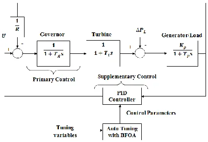
Fig. 1 shows the LFC in single area thermal power system. Primary control action here is provided by the
speed governor alone and the supplementary control originating at central control center allocated generation.
The common nominal system parameters quoted in most of the references [8] are used in this paper. They are
𝑃𝑟= 1000 𝑀𝑊; 𝑇𝑔 = 0.2 𝑠; 𝑇𝑡 = 0.3𝑠; 𝑇𝑝= 20 𝑠;
𝐾𝑝 = 120 𝐻𝑧/ 𝑝𝑢; 𝑅 = 2.4 𝐻𝑧 /𝑝𝑢𝑀𝑊; 𝑓 = 60 𝐻𝑧;
B. Automatic Voltage Regulation
The main objective of AVR is to contribute for the effective control of voltage and enhancement of system stability. Generally, the role of AVR is to hold the terminal voltage magnitude of synchronous generator at a specifiedlevel.
Fig. 2 Schematic block diagram of AVR
In addition, the AVR must be able to respond to a transient disturbance with field forcing consistent with the generator instantaneous and short term capabilities. It should also be capable of responding to disturbance so as to enhance transient stability and of modulating generator field so as to enhance small signal stability. Fig. 2 shows the functional block diagram of typical AVR loop. The primary means of generator reactive power control in this AVR loop is done with the excitation control and the supplementary control action is provided with a PID controller.
The interaction between voltage and frequency control is generally weak. So in this paper the analysis of LFC and AVR are carried out separately. The nominal system parameters of AVR investigated in this paper are same as the parameter commonly quoted in most of the research papers [9]. They are:
𝐾𝐴= 10; 𝐾𝐸= 𝐾𝐺= 𝐾𝑅= 1; 𝑇𝐴= 0.1𝑠
𝑇𝐸= 0.4𝑠; 𝑇𝐺= 1𝑠; 𝑇𝑅= 0.01𝑠
III. TUNING OF PID CONTROLLER
A. Ziegler-Nichols continuous cycling method
Copyright to IJIRSET www.ijirset.com 126 analysis to design the PID gain parameters using ZN
continuous cycling method is as follows
The polynomial characteristic equation of LFC and AVR are designed as shown in (1) and (2).
𝐺 𝑠 𝐻 𝑠 = 𝐾𝑐𝑟∗ 𝐾𝑝
𝑅 𝑇𝑝𝑠 + 1 𝑇𝑔𝑠 + 1 𝑇𝑡𝑠 + 1
(1 )
𝐺 𝑠 𝐻 𝑠 = 𝐾𝑐𝑟∗ 𝐾𝐴𝐾𝐸𝐾𝐺𝐾𝑅
𝑇𝐴𝑠 + 1 𝑇𝐸𝑠 + 1 𝑇𝐺𝑠 + 1 𝑇𝑅𝑠 + 1
( 2)
The critical gain constant (𝐾𝑐𝑟) and the time
constant (𝑇𝑐𝑟) are obtained by solving (1 and 2)
with Routh Hurwitz stability criterion without violating the stability margin.
The constants 𝐾𝑐𝑟and 𝑇𝑐𝑟 are substituted in
Table I and the following gain parameters are evaluated as
For LFC- 𝐾𝑃=3.872428, 𝐾𝐼=8.031838, 𝐾𝐷=0.466758.
For AVR -𝐾𝑃=1.021006, 𝐾𝐼=1.87429, 𝐾𝐷=0.139046.
TABLE I
CALCULATIONOF PID PARAMETERS
Control type 𝑲𝑷 𝑻𝑰1 𝑻𝑫2
P 0.5𝐾𝑐𝑟 ∞ 0
PI 0.45𝐾𝑐𝑟 𝑇𝑐𝑟
1.2 0
PID 0.6𝐾𝑐𝑟
𝑇𝑐𝑟
2
𝑇𝑐𝑟
8
The disadvantages of conventional PID controller are already being discussed in Section I. Hence, an idea of using artificial intelligent techniques got strengthened. This paper proposed one of the swarm based artificial intelligent technique named BFOA for the effective tuning of PID controller.
B. BFOA Tuned PID Controller
The BFOA is one of the swarm based optimization algorithm which is built with a key idea of foraging strategy of E. coli bacteria [10]. On this accord BFOA mimics four principle mechanisms in real bacterial system. They are
Chemotaxissimulated the movement of E. coli through swimming and tumbling via flagella similar to which the randomly assigned solutions are moved in a search space.
Swarming is the interesting grouping behavior of the motile species. In this mechanism the E. coli cells are arranged themselves in a travelling ring and moving towards the nutrient. The cells when stimulated by a high level of succinate will release an attractant aspartate which helps them to align in a group. In optimization problem this phenomenon is used to move the solutions towards an optimal point.
Reproduction helps to keep the swarm size constant in a search space by omitting the least healthy bacteria and by splitting the healthiest bacteria in to two. Similar to which the solutions yields low objective functions in minimization problems is reproduced and the solutions with maximum value of objective are discarded from the search space. Both LFC and AVR in this paper using a minimization objective function as shown in (3 and 4).
𝐽1= 𝐼𝑇𝑆𝐸 = ∆𝑓2 . 𝑡. 𝑑𝑡 𝑡𝑠𝑖𝑚
0
(3)
𝐽2= 1 − ∆𝑣−𝛽 𝑀𝑝+ 𝐸𝑠𝑠 + ∆𝑣−𝛽 𝑇𝑠− 𝑇𝑟 (4)
where, ∆𝑓 and ∆𝑣 are deviation in frequency and voltage correspondingly, the value of constant 𝛽 is taken as 0.5, 𝑡𝑠𝑖𝑚 in the maximum simulation time and it is
taken as 20s in this paper, 𝑀𝑝is the maximum peak of the
output wave form, 𝐸𝑠𝑠 is the steady state error and 𝑇𝑠, 𝑇𝑟
are settling time and rise time respectively.
Elimination and Dispersal is happened due to the occurrence of sudden environmental changes or attack. A group of bacteria may liquidate randomly with a very small probability and some new one will be introduced to swarm of concern. This process helps in reducing the behavior of stagnation often seen in parallel search algorithms.
IV. RESULTS AND DISCUSSIONS
A. Transient analysis of LFC with BFOA tuned PID controller for step change in load
The single area thermal power system [8] shown in Fig. 1 is considered as a test system in this section for the proposed approach.
TABLE II
COMPARATIVE TRANSIENT ANALYSIS OF LFC
Methods
Measuring Parameters for Frequency Deviation
Settling Time
(s)
Maximum Peak (Hz)
Peak Time (s)
Error (Hz)
NCS 10 0.01625 0.40491 0.00251
Integral 4.46243 0.02834 0.76303 6.09638×10⁻⁴
ZN- PID 1.93634 0.00641 0.18364 2.36978×10⁻⁶ BFOA 1.49416 0.00586 0.15285 1.52200×10⁻⁶
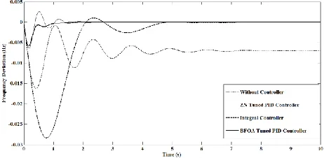
Initially, the transient performances of the single area LFC for 1% load perturbation is obtained by way of BFOA tuned PID controller with 𝐽1 . The BFOA
parameters used for both LFC and AVR are
Number of bacteria =10; Number of Chemotactic steps =10; Length of swim=4; Number of reproduction steps = 2; Probability of elimination and dispersal = 0.25; Number of elimination and dispersal events = 2.
The PID parameters evaluated by this method are 𝐾𝑃=3.1851, 𝐾𝐼=4.6725, 𝐾𝐷=0.6556. Then to show the
effectiveness of the proposed approach, the results of proposed algorithm are compared with NCS, integral controller and ZN -PID enforced to the same power system. Fig. 3 illustrates the comparative analysis made between the transient performances of LFC with different approaches. The measuring parameters affiliated to this figure are scheduled in Table II and it clearly reveals that the total error evaluated using 𝐽1 in the proposed
approach is considerably reduced to 64.225% compared to ZN tuned PID controller. Similarly, the Maximum peak reduced to 91.42% and 20.677% compared to ZN method and Integral controller respectively. Compared with same controllers, the settling time of the proposed method is improved by 0.4422s and 2.968s respectively.
Hence, it is distinctly demonstrated from the above analysis that, the transient characteristics of single area LFC are enhanced with the proposed approach comparing to other conventional approaches.
B. Transient analysis of AVR with BFOA tuned PID controller for step change in 𝑉𝑟𝑒𝑓
The AVR system [9] shown in Fig. 2 is considered as a test system in this section for the proposed approach.
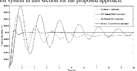
Fig. 4 Comparative transient performances of AVR for Vref=1%
TABLE II
COMPARATIVE TRANSIENT ANALYSISOF AVR
Methods
Measuring Parameters for Voltage Deviation Settling
Time (s)
Maximum Peak (V)
Peak
Time (s) Error (V)
NCS 10 0.01505 0.76384 8.8106×10⁻⁴
ZN- PI 9.96854 0.01786 0.85966 1.6901×10⁻⁴ ZN- PID 3.64848 0.01529 0.64652 2.9709×10⁻⁸
BFOA 1.10280 0.01073 0.41146 2.4597×10⁻⁸
Similar to LFC, the transient performances of the AVR test system for 1% load perturbation is obtained by way of BFOA tuned PID controller with 𝐽2objective function.
The PID parameters evaluated by this method are 𝐾𝑃 =0.7886, 𝐾𝐼 =0.6085, 𝐾𝐷 =0.3357. To show the
effectiveness of the proposed approach, the results are compared with Non Controller System (NCS), ZN tuned PID controller (ZN- PID) and ZN tuned PI controller (ZN- PI). The transient performances of AVR with different approaches are exemplified in Fig. 4 and the measuring parameters affiliated to this figure are scheduled in Table III. It is clear from the table that the total error reduced to 82.79% compared to ZN-PID controller. The Maximum peak also reduced to 60.08% and 70.16% compared to ZN tuned PI controller (ZN-PI) and ZN-PID controller respectively. Compared with same controllers, the settling time of the proposed method is improved by 8.866s and 2.545s respectively. The above analysis clearly reveals the superiority of the proposed BFOA tuned PID controller for AVR compared to other approaches.
C. Transient analysis of LFC and AVR with BFOA tuned PID controller for variable load changes
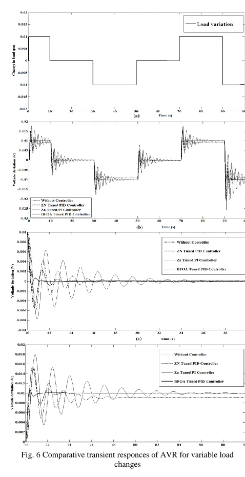
To scrutinize the non linear behavior and practical adaptability of the LFC and AVR test system, instead of fixed step change in load, the variable load ranges between (0-100s) as indicated in Fig. 5a are applied to both the systems.
Copyright to IJIRSET www.ijirset.com 128
Fig. 5 Comparative transient responces of LFC for variable load changes
Further, the voltage control effects of different methods such as NCS, ZN-PI controller, ZN-PID controller and BFOA tuned PID controller for the AVR test system are comparatively investigated under the time varying load shown in Fig. 6a. The output response for voltage deviations for all these approaches is obtained as shown in Fig. 6b. For clear illustration randomly selected portions of the Fig. 6b in the time ranges of (10-30s) and (70-90s) are enlarged as shown in Fig. 6c and Fig. 6d respectively. Both these figures clearly demonstrate that the number of oscillations, maximum overshoot, steady state error and settling time are considerably reduced with the proposed approach over others and hence makes the controller more versatile to the practical environment.
Fig. 6 Comparative transient responces of AVR for variable load changes
V. CONCLUSIONS
difficulties faced by the practitioners while using conventional fixed gain PID controller.
NOMENCLATURE 𝑃𝑟 Rated power (MW)
𝑇𝑔 Steam governor time constant (s)
𝑇𝑡 Steam turbine time constant (s)
𝐾𝑝 Power system gain constant (Hz/ pu)
𝑇𝑝 Power system time constant (s)
𝑅 Governor speed regulation (Hz/ pu MW)
𝐾𝐴 Amplifier gain constant
𝑇𝐴 Amplifier time constant (s)
𝐾𝐸 Exciter gain constant
𝑇𝐸 Exciter time constant (s)
𝐾𝐺 Generator gain constant
𝑇𝐺 Generator time constant (s)
𝐾𝑅 Sensor gain constant
𝑇𝑅 Sensor time constant (s)
REFERENCES
[1] P. Kundur, Power system stability and control, 8th ed., McGraw-Hill: New York, 1994, pp.581-622.
[2] M. Nagendra, M.S. Krishnarayalu, “AGC and AVR of multi area power systems with and without GRC nonlinearity,” International journal of advanced research in electrical electronics and instrumentation engineering, vol. 2, issue 6, pp. 2117-2126, June 2013.
[3] Ahmad M. Hamza, Mohamed S. Saad, Ahmed Bahgat, “Design of LFC and AVR for single area power system with PID controller tuning by BFO and Ziegler Methods,” International Journal of Computer Science and Telecommunications, vol. 9, issue 5, pp. 12-17, May 2013.
[4] K. J. Astrom, T. Hagglund, Ahmed Bahgat, “The future of PID control,” Control engineering practice, vol. 9, pp. 1163-1175, April 2001.
[5] H. Golpîra, H. Bevrani, H. Golpîra, “Application of GA optimization for automatic generation control design in an interconnected power system,” Energy Conversion and Management, vol. 52, pp. 2247-2255, 2011.
[6] Hamed Shabani, Behrooz Vahidi, Majid Ebrahimpour, “A robust PID controller based on imperialist competitive algorithm for load-frequency control of power systems,” ISA Transactions, vol. 52, pp. 88-95, 2013.
[7] V. Mukherjee, S.P. Ghoshal, “Intelligent particle swarm optimized fuzzy PID controller for AVR system,” Electric power system research, vol. 77, pp. 1689-1698, Jan 2007.
[8] Saumya Kr. Gautam, Nakul Goyal, “Improved particle swarm optimization based load frequency control in a single area power system,” Annual IEEE India conference (INDICON 2010), Kolkata, Dec 2010.
[9] Z.L. Gaing, “A particle swarm optimization approach for optimum design of PID controller in AVR system,” IEEE Trans. Energy conversion, vol. 19, pp. 384-391, June 2004.