Design and Implementation of Wireless Water
Level Management System Using Zigbee
Technology
Naseeruddin 1, V C Patil 2
Research Scholar, Dept. of Electronics & Communication, Ballari Institute of Technology Management, Ballari, India1
Professor, Dept. of Electronics & Communication, Ballari Institute of Technology Management, Ballari, India2
ABSTRACT: This paper proposes a wireless water level management system using zigbee technology. The present work investigates water level management system implementation using ultrasonic sensors, zigbee modules and other components resulting into a prototype. The prototype has been successfully tested under laboratory conditions.
KEYWORDS: Water, Wireless Sensor Network (WSN), GPRS (General Purpose Radio Service), Zigbee I. INTRODUCTION
Water management is a key issue affecting 21st century globally. Due to globalization and rapid industrialization drinking water resources are becoming sparse. The onus of water conservation is upon everyone living in the society. The best way to conserve the drinking water is to manage it in the best possible ways and at all possible places. The proposed work focuses on design of water management system at homes having two to three floors using zigbee modules in a cost effective way. The zigbee is wireless sensor equipped with a radio transceiver and a set of
transducers through which it acquire information about the surrounding environment. Zigbee technology is embedded
in a wide range of products and applications across consumer, commercial, industrial and government markets worldwide. The zigbee is built upon the IEEE 802.15.4 standard [1].The proposed system prototype has been successfully tested in the laboratory environment. The rest of the paper is organized into following sections. Section 2 reviews previous work done in the field of water management using wireless communication assisted methods. Sections 3 describes proposed system, section 4 gives implementation of the proposed system. Section 5 finally gives conclusion and future research directions.
II. RELATED WORK
water. Proposed system is cost effective but it is far from perfection. As per the literature available and those we could gather it is observed that large part of the literature is dedicated on wireless monitoring using available sensors either for industries or very large geographical areas. Hence there is need to apply wireless technology effectively for thousands of homes and help in sustainability of water.
III. PROPOSED WIRELESS WATER MANAGEMENT SYSTEM USING ZIGBEE PROTOCOL
Figure 1: Block diagram of proposed wireless water management system
The block diagram Figure. 1 gives the outline of the proposed system along with its components. It describes two main sections of the system, transmitting section and receiving section. Transmitting section has a wireless level sensor, a microcontroller and Zigbee module. The receiving section consists of a wireless level sensor, relay logic, microcontroller, Zigbee module, pump motor and power Supply. The technique of water level monitoring and controlling system concentrated with some basic parts which are softly aggregated together in the proposed system. The proposed system takes into consideration sump tank water level priority. This is a unique feature that has been extracted from a pair of zigbee sensors.
IV. SYSTEM IMPLEMENTATION AND TESTING
Implementation is of the proposed system is done in two parts as described below HARDWARE IMPLEMENTATION
The different hardware components used are as follows
A. For the Overhead Tank
1. Wireless Water Level Sensor 2. Microcontroller Module 3. Zigbee Transceiver
B. For the Sump
3. Zigbee Transceiver 4. Relay Circuit 5. Pump Motor
Figure 2: Circuit diagram of overhead tank Figure 3: Circuit diagram of Sump
The hardware implementation for overhead tank (Figure 2) and sump (Figure 3) is as shown in the above circuit diagram. It has two microcontrollers placed one at the tank and another at the sump. They perform the task of controlling, level detection and sequencing the communication. The ultrasonic sensor is used to calibrate the water levels in overhead and sump tanks. Then appropriate calibrated water levels are designated as low warning or high warning levels. Whenever water reaches any of these levels microcontrollers at the respective tanks react and start communicating wirelessly using zigbee device (here Tarang P20).Based on the information communicated by zigbee device sump tank or overhead tank status will be evaluated and appropriate decision will be initiated by the microcontroller at the tanks. Details of the implementation are described in the following section.
ULTRA SONIC SENSOR HC-SR04 [8]
This is used to detect the water level, then the data will go to transmit and receive through the Zigbee module and the whole procedure is going control by the microcontroller. Ultrasonic sensor generates high frequency sound waves and evaluates the echo from the water level of the reservoir which is received back by the sensor. The working principle of an ultrasonic sensor is simple and use high frequency sound waves that are evaluated when the sensor receives back the waves. Sensors Module calculates the time interval between transmitting pulse and receiving the echo to determine the distance of water level height from the bottom of reservoir/tank. The ratio of this time interval to the speed of sound in air gives the exact level of water in centimetres. These sensors are ideal for measurement in different environments where measurements cannot be affected by the surface, material, light, dust, or other noises. It is powered by 5v dc [4]. The trigger pin is connected to the pin13 and echo pin is connected to the pin12 of Uno. Trigger pin is the output pin and echo pin is the input pin. The modes of the pins are set by the Arduino software.
ZIGBEE TARANG P20
DB-9 port is connected to the DB-9 port of the MAX232 which is connected to the Uno through TX and Rx pins. The TX pin of the MAX232 is connected to RX pin of Uno and RX pin to the TX.
ARDUINO UNO
The Arduino Uno is a microcontroller board based on the ATmega328. It collects the data from the Ultrasonic Sensor and then decides the task to be performed upon receiving the level sensing data from both the modules. The digital input/output pins are used to connect to the level sensor [11][12]. Upon receiving the sensing data, it converts into distance and then to level of water by mapping the distances into levels. High warning level and Low warning level are considered for powering the motor ON/OFF. Condition for switching motor ON/OFF is discussed in the software implementation section.
RELAY CIRCUIT
A relay is an electrically operated switch. Relays are used where it is necessary to control a circuit by a low-power signal with complete electrical isolation between control and controlled circuit or where several circuits must be controlled by one signal. In fig.3 the 12v and Ground pin is connected to power supply and is switched using the input by sending high pulse when motor to switch on and low pulse for motor switch off.
PUMP MOTOR
A submersible AC motor is used along with the relay circuit to switch ON/OFF according to the input from the micro-controller. A 220v AC power supply is provided from the main stream and it can drive water up to 1.85m. This pump motor is used for the prototype model. Original motors can drive as per their specifications.
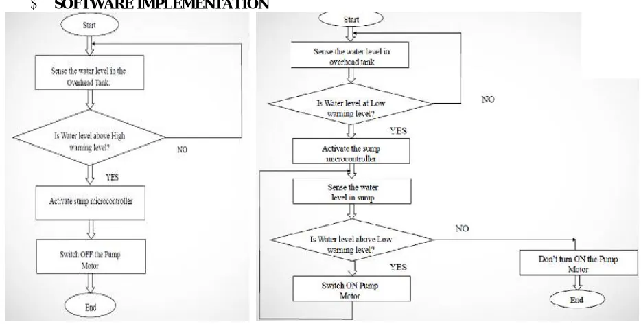
SOFTWARE IMPLEMENTATION
Figure 4: OVERHEAD TANK MODULE Figure 5: SUMP TANK MODULE
warning level it will switch ON the pump motor. After switching ON, both the microcontrollers periodically check for the warning level of water. Overhead Tank checks for High warning signal and sump checks for Low warning signal. When water in the tank reaches High warning level it requests for motor to switch OFF the motor. If water level in sump reaches Low warning level it also requests motor to switch OFF. Either of the tanks can switch the motor OFF before the other reaches a warning level. If water in the overhead tank is Low and water in the sump is also Low, motor is not allowed to switch ON. It bypasses the condition of Low water level warning in the tank.
1. Initialize the water level management system.
2. Sense the water level in overhead tank using Ultrasonic sensor and process the data in Arduino Uno to derive
the water level.
3. If the water level is at low warning level in the overhead tank, a signal is sent to check the water level of sump and then to switch ON the motor if the water level of sump is above low warning level.
4. If the water level in sump is above Low warning level, then the motor is switched ON. Water level of sump is
periodically sensed for Low warning level. When sump water level reaches Low warning level, motor is switched OFF.
5. When motor is switched ON, Overhead tank senses for High warning level periodically. If the water in tank
reached high warning level before sump reaches low warning level, the pump motor is switched OFF. 6. Sensing of water level in overhead tank and sump is done periodically to maintain the water level.
Testing was carried out on each module mentioned below and finally an integrated module was tested as mentioned below.
Case1: Testing of Ultrasonic module HC-SR04 and Arduino UNO
A basic code of ultrasonic distance sensing is compiled and uploaded onto the micro-controller in UNO board. A small card board piece is placed in line of sight with the sensor. The distance between the obstacle and the sensor was measured and found to be accurate.
Case2: Testing of module of Tarang P-20, MAX232 and Arduino UNO
A basic code of buzzer is compiled and uploaded onto the micro-controller in the UNO board. This module is working intact at a near distance up to 40m of horizontal axis without line of sight. Later by extending the working of Tarang P-20 module pair to vertical axis, the module is placed at different floors of a building to measure vertical distance. At the first floor transmission result was appropriate. Similarly at the second floor there was transmission with a negligible delay. When taken third floor there was fading of signal due to interference and resulted in two second delay.
Case3:Testing of module of HC-SR04, Tarang P-20, MAX232 and Arduino UNO
An integrated code of ultrasonic distance sensing and buzzer is compiled and uploaded onto the micro-controller in the UNO board & connected as shown in fig.8 and then executed. The distance between the obstacle and the sensor was measured and calibrated into levels. Assigning Low and High warning levels, a buzzer is made to ring upon reaching either of the warning levels. Distance and levels were continuously monitored at the Serial monitor of the Arduino-1.6.3 programmer.
Case4: Testing of module of HS-SR04, Tarang P-20, UNO and Pump Motor
The final code of distance measurement, calibration of distance into different warning levels, transmission and reception and switching ON/OFF through relay is compiled and uploaded onto the micro-controller in the UNO board and executed. Following are the testing results obtained for different water levels.
The following are the observations resulted from the project’s implementation. (Please refer Figure 6 showing the complete modules of the proposed system)
1. The output of the sensor is observed by varying the distance of obstacle (cardboard).
2. The distance of water level is verified and then calibrated into warning levels at the microcontroller.
3. Working of Zigbee protocol is checked by dumping a buzzer program and the transceiver module is checked
for wireless transmission.
4. The transceiver pairs were taken to the different floors of the building and checked for transmission and reception. It is observed that after three floors the signal is fading due to interference and delay of signal is found.
5. Module of UNO, HC-SR04 and Tarang P-20 is by verified by distance & calibration and buzzer program.
7. Pump Motor is switched ON water is pumped when the water in sump is above Low warning level and water in overhead tank is at Low warning level.
8. Pump Motor is switched OFF water is pumped when the water is sump is at Low warning level or water in overhead tank is at High warning level.
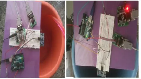
Figure 6: Overhead Tank and Sump Tank complete modules
Figure 6 shows the complete experimental set up of the overhead and sump tank modules tested in the laboratory environment. A cooler pump was used for demo purpose of the experimental setup. Many test trails were conducted. It is experimentally observed that vertically 25-30 feet and horizontally about 70 feet wirelessly water management system performed satisfactorily.
V. CONCLUSION AND FUTURE RESEARCH DIRECTIONS
Water is one of the most important basic needs for all living beings. But unfortunately a huge amount of water is being wasted by uncontrolled use. Existing water level management systems have own advantages and drawbacks in addressing this issue. With this work we tried to overcome the problems and implemented an efficient wireless water level management system. The intention of the work was to establish a flexible, economical and easy configurable system which can solve our water wastage problem. In future more number of zigbee nodes can be added into the system for covering large buildings such as colleges, offices, companies, apartments and so on for better and efficient water usage. Further system can be enhanced by integrating GPRS to have unlimited wireless range and solar panel to take care of power crisis.
REFERENCES
[1] Paolo Baronti et el.., “Wireless sensor networks: A survey on the state of the art and the 802.15.4 and ZigBee standards,” Journal of Computer Communications(30), Elsevier ,pp.1655-1695, 2007. (doi:10.1016/j.comcom.2006.12.020 ).
[2] S. M. Khaled Reza., Shah Ahsanuzzaman Md. Tariq., and S.M. Mohsin Reza., “Microcontroller Based Automated Water Level Sensing and Controlling: Design and Implementation Issue”, Proceedings of the World Congress on Engineering and Computer Science,Vol 1, pp.1-7, 2010. [3] LieGuo Wu, Lingcheng Kong and Zhihua Zhang, “Water Environment Monitoring System Based On ZigBee Wireless Sensor Network,” ,
proceeding of IEEE 4th International Conference on Software Engineering and Service Science (ICSESS 2013), Beijing, China,pp.898-901, 23-25 May 2013.
[4] Abdullah-Al-Mamun, Nasim Ahmed, Nizam Uddin Ahamed, S. A. M. Matiur Rahman, Badlishah Ahmad and Kenneth Sundaraj, “Use of Wireless Sensor and Microcontroller to Develop Water-level Monitoring System”, Indian Journal of Science and Technology, Vol 7(9), 1321– 1326, September 2014.
[5] Ramazan Bayindir a, Yucel Cetinceviz, “A water pumping control system with a programmable logic controller (PLC) and industrial wireless modules for industrial plants—an experimental setup,” ISA Transactions 50, Elsevier, pp.321-328, 2011. (doi:10.1016/j.isatra.2010.10.006). [6] Víctor-M. Sempere-Payá , Salvador Santonja-Climent, “Integrated sensor and management system for urban waste water networks and
[7] Xin Wang, Longquan Ma, Huizhong Yang, “Online Water Monitoring System Based on ZigBee and GPRS,” Procedia Engineering 15 Advanced in Control Engineering and Information Science, Elsevier ,pp. 2680-2684, 2011. (doi:10.1016/j.proeng.2011.08.504).
[8] http://www.micropik.com/PDF/HCSR04.pdf
[9] http://www.melangesystems.com/Pdfs/Tarang%20-%20Product%20Manual%202.2.pdf [10]https://fccid.net/document.php?id=1723546