CFD Analysis of Cross Flow Heat Exchanger
and Experimental Validation
Utkarsh Wani1, Shivam Kulkarni2, Abhishek Keskar3
Design Analyst, Dept. of Mechanical Engineering, a^2 Innovation Research and Training, Warje, Pune, India1
Design Analyst, Dept. of Mechanical Engineering, a^2 Innovation Research and Training, Warje, Pune, India2
Head Design Analyst, Dept. of Mechanical Engineering, a^2 Innovation Research and Training, Warje, Pune, India3
ABSTRACT: Enhancing the heat transfer by use of an elliptical shaped tube blank has been studied and research by many researcher because the fluid dynamics outside the elliptical shaped tube offers the more advantage over the circular shaped tubes. In present study, 2D-CFD analysis of the elliptical shaped tube in outside insulated cross flow heat exchanger with in-line arrangement and 45o angle of attack is carried out. The inlet and outlet temperature of hot water is constant at 80oC passed through an array of 30 SS204 tubes arranged at 45o angle of attack. The tubes are 150mm long with longitudinal and transverse pitch 52mm. The tubes are oriented at 45o angle of attack with direction of air flow. Thermal hydraulic performance of tube is carried out by varying mass flow rate of air and its effect on Nusselt number, Reynolds number, convective heat transfer coefficient, overall heat transfer coefficient is studied and validated with experimental results using ANSYS FLUENT 18.1 where the governing equations of mass, momentum and heat transfer were solved simultaneously, using the k-epsilon turbulence model. Result shows that various contours and vectors of temperature, velocity, pressure distributions, eddies formation and pressure drop at the end of tube is visualized. The percentage of error in outlet temperature of air from validation of CFD and experimental is 1 to 3 % and the enhancement ratio of elliptical shaped tube blank is 1.3 to 1.7 range compare to circular shaped tube blank in 9273.9 to 21000 Reynolds number range.
KEYWORDS: Cross flow heat exchanger, Elliptical tube blank, CFD Analysis
I. INTRODUCTION
A heat exchanger is a device that is used to transfer thermal energy between two or more fluids, between a solid surface and a fluid, or between solid particulates and a fluid, at different temperatures and in thermal contact. A heat exchanger consists of heat transfer elements such as a core containing the heat transfer surface, and fluid distribution elements such as headers, manifolds, tanks, inlet and outlet nozzles or pipes, or seals. Usually, there are no moving parts in a heat exchanger; however, there are exceptions, such as a rotary regenerative exchanger in which the matrix is mechanically driven to rotate at some design speed or a scraped surface heat exchanger. The heat transfer is a surface of the exchanger core that is in direct contact with fluids and through which heat is transferred by conduction. That portion of the surface that is in direct contact with both the hot and cold fluids and transfers heat between them is transfer to as the primary or direct surface. To increase the heat transfer area, appendages may be intimately connected to the primary surface to provide an extended, secondary, or indirect surface.
Classification of Heat Exchanger based on Flow Arrangement
a) Parallel flow exchanger:
In a parallel flow exchanger, the fluid streams enter together at one end, flow parallel to each other in the same direction, and leave together at the other end. This arrangement has the lowest exchanger effectiveness among single-pass exchangers for given overall thermal conductance (UA) and fluid flow rates (actually, fluid heat capacity rates) and fluid inlet temperatures; however, some multi-pass exchangers may have an even lower effectiveness, as discussed later. Fig. 1.1 shows the parallel flow heat exchanger.
Fig. 1.1 Parallel Flow Heat Exchanger
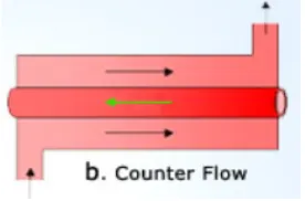
b) Counter flow exchangers:
In a counter flow or counter current exchanger the two fluids flow parallel to each other but in opposite directions within the core. The counter flow arrangement is thermodynamically superior to any other flow arrangement. it is the most efficient flow arrangement, producing the highest temperature change in each fluid compared to any other two-fluid flow arrangements for a given overall thermal conductance (UA), two-fluid flow rates (actually, two-fluid heat capacity rates), and fluid inlet temperatures. . Fig. 1.2 shows the counter flow heat exchanger.
Fig. 1.2 Counter Flow Heat Exchanger
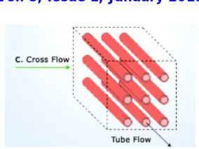
c) Cross flow exchanger:
Fig. 1.3 Cross Flow Heat Exchanger
Heat Transfer Coefficient
Convective heat transfer, is the transfer of heat from one place to another by the movement of fluids due to the difference in density across a film of the surrounding fluid over the hot surface. Through this film heat transfer takes place by thermal conduction and as thermal conductivity of most fluids is low, the main resistance lies there. Heat transfer through the film can be enhanced by increasing the velocity of the fluid flowing over the surface which results in reduction in thickness of film. The equation for rate of heat transfer by convection under steady state is given by, Q = h A (Tw –Tatm)
Where, h is the film coefficient or surface coefficient (W/m2k) A is the area of the wall,
Tw is the wall temperature and Tatm is surrounding temperature.
The value of h depends upon the properties of fluid within the film region; hence it is called ‘Heat Transfer Coefficient’. It depends on the different properties of fluid, dimensions of the surface and velocity of the fluid flow (i.e. nature of flow).
The overall heat transfer coefficient is the overall transfer rate of a series or parallel combination of convective and conductive walls. The ‘Overall Heat Transfer Coefficient’ is expressed in terms of thermal resistances and its inverse is the overall heat transfer coefficient, U.
1 = 1
ℎ +
1
ℎ + + +
Where, U=Overall heat transfer coefficient based on outside area of tube all A= area of tube wall
h= convective heat transfer coefficient Rf= thermal resistance due to fouling
Rw = thermal resistance due to wall conduction and suffixes ‘O’ and ‘I’ refer to the outer and inner tubes, respectively.
Fig 1.3 shows the wall convection
.
Fig.1.3 Wall Convection
Computational Fluid Dynamics
Computational Fluid Dynamics, abbreviated as CFD, uses different numerical methods and a number of computerized algorithms in order to solve and analyse problems that involve the flow of fluids. The calculations required to simulate the interaction of fluids with surfaces defined by boundary conditions, and initial conditions are done by the ANSYS Fluent v13.0. The Navier Stokes equations form the basis of all CFD problems. Two equation models are used for the simulations, and different models are discussed below.
The continuity equation, energy equation and the Navier-Stokes momentum equation govern the flow of the fluid in the curve tubes.
Continuity Equation gives the conservation of mass and is given by
+ + + = 0
=> + = 0
And for constant density, = 0
The momentum balance, (Navier-Stokes equations) follows Newton’s 2nd law. The two forces acting on the finite element are the body and the surface forces. In CFD programmes, the momentum equation is given as
+ = − − +
The governing energy equation is given by:
+ =
Turbulence is created because of the unstable nature of the fluid flow. The flow becomes turbulent for higher Reynolds number. In this model the k-ε (turbulent kinetics energy “k” and the turbulent dissipation “ε”) model is used.
The physical interpretation of the ε equation is, 1. Accumulation of ε
2. Convection of ε by the mean velocity
4. Dissipation of ε
5. Diffusion of ε
The time constant for turbulence is determined from the turbulent kinetic energy and dissipation rate of turbulent kinetic energy.
= Steps in CFD Analysis
Pre processor
Geometry generation
Geometry clean-up
Meshing
Solver
Problem specification
Additional models
Numerical computation
Post Processor
Line and Contour data
Average Value
II. LITREATUREREVIEW
The literature review is carried out in order to see the present research in this area which elaborated under present status. Toolthaisong et al. [1] conducted experimental investigation of the air side heat transfer and pressure drop characteristics at steady state for the cross flow heat exchangers having flat tubes. The results show that the thermal and pressure drop characteristics is governed by the angle of attack and axis ratio. The experimental setup consisted of flat tubes through which hot water was circulated. The air was passed over the tubes with velocity varying in the range of 2 to 6 m/sec. It was noticed that for all values of air velocity and axis ratio, the pressure drop and heat transfer rate increased with increasing angle of attack 0 to 90 degree; while the thermal hydraulic performance was decreased. For the tubes aspect ratio 0.18, 0.36 and 0.66, the pressure drop for 90 degree angle of attack was higher than 0 degree angle of attack by 17.8times, 5.5 times and 1.8 times respectively.
Ibrahim et al. [2] carried out experimental and numerical investigation of the turbulent flow through bundle of elliptic tubes heat exchanger. They investigated the effect of design parameters such as minor to major axis ratio and flow of angle of attack. The experiment was conducted on five bundle of elliptic tube heat exchanger with different axis ration. From experimental date it was found that increasing angle of attack clockwise until 90o enhances the convective heat transfer coefficient considerably. The heat exchanger with 0o angle of attack has the highest value of the efficiency index, which is the ratio between the Stanton number enhancement ratio (St/St0) to the friction factor ratio (f/f0). The maximum thermal performance (heat transfer per unit pumping power) occurred at 0o whereas the minimum thermal performance of the elliptic occurred at 90o angle of attack. The elliptic tube bundle produced a considerable frontal area reduction of heat exchanger at 0o angle of attack with minor to major axis ratio 0.25 to 1.
to fin spacing ratio was 2.16 and 22 respectively. They found out Nusselt number correlation for both heat exchangers with different angle of attack. In case of three row tubes heat exchanger with 45o angle of attack Nu = 1.63×Re0.39 and f =70.79 Re-0.38 whereas for 90o angle of attack, Nu = 2.09×Re0.37& f=119×Re0.45 correlation was obtained by the researcher. The heat transfer rate for 30o, 45o, 60o angle of attack was compared with the heat transfer rate for 90o.
Sun et al. [4] compared the overall thermal performance of refrigerant to air finned tube condensers with elliptical and circular tubes. The result shows that the air pressure drop and the heat transfer rate of elliptical condenser are 20%-27.3% lower and 8.3% to 30.9% higher than those of circular tube condenser respectively. Compared to circular tube condenser, the system capacity improvement using elliptical condensers was found to be high a 21.3%-27.5% whereas the COP improvement rangers from 3.6to 6.7%. The study experiment was conducted using different refrigerants. The result shows the elliptical tube condenser using R410a yield higher improvement of condenser heat transfer rate and system capacity than using R22 and R134a.
Hui Han et al. [5] carried out experimental investigation on three different kinds of tubes with two types of enhanced fins, wavy fins and louvered fins. The results revealed that using the oval fin tube can not only reduce the flow resistance but also improve the host trader capacity go the heat exchangers. As comparing with the circle tube louver fin, the heat transfer rate of oval tube fin was found to be increased by 1.5-4.9% while the pressure drop loss was decreased by 22% to 31.8%.
Hasan et al. [6] analysed the performance of two evaporative cooled heat exchangers with plain circular tubes and other with oval tubes. It was concluded that the average mass transfer Colburn factor j for the oval tubes 89% of that for the circular tube, while the average friction factor for the oval tube is 46% of that for the circular tube. The ratio j/f for the oval tube is 1.93-1.96 times that for the circular tube. This means that for the oval tube has a better combined thermal-hydraulic performance.
Lavasani et al. [7] experimentally investigated flow around cam shaped tube bank with inline arrangement. It was found that friction factor of cam shaped tube bank is about 95% and 93% lower than the circular tube bank. By increasing longitudinally pitch ratios from 1.5to 2, heat transfer increases about 7%to 14%. Thermal hydraulic performance of cam shaped tube bank was about 6 times greater than circular tube bank due to aerodynamic shape of cam shaped tubes.
Khan et al. [8] experimentally investigated flows of hot air at 41.5+1.5 oC across an array of elliptical tubes carrying cold water. He results showed that the heat transfer rate increased with the increase in both water and air flows. The pressure coefficient (Cp), across a single tube in the array was found to remain at approx. 0.16 for Rea> 2 × 10⁴. Both heat transfer rate and mussel number (Nu) were found to vary in power law relationship with Re. The Nu-Re correlation obtained from the idealized test bench was found to be in the form Nua= 0.26×Rea0.66.
Tao et al. [9] performed three dimensional numerical studies for laminar heat transfer and fluid flow characteristics of wavy fin heat exchangers with elliptic/circular tubes. A max relative heat transfer gain up to 30% was observed in the elliptic arrangement and corresponding friction factor only increased by about 10%. The result show that with the increasing of Reynolds number and fin thickness, decreasing of the eccentricity and span wise tube pitch, the heat transfer of the finned tube bank are enhanced with some penalty in pressure drop.
III.CFDANALYSIS
Computational fluid dynamics (CFD) study of the system starts with the construction of desired geometry and mesh for modelling the dominion. Generally, geometry is simplified for the CFD studies. Meshing is the discretization of the domain into small volumes where the equations are solved by the help of iterative methods. Modelling starts with the describing of the boundary and initial conditions for the dominion and leads to modelling of the entire system. Finally, it is followed by the analysis of the results, conclusions and discussions.
Assumption for CFD Analysis
1. In 2d analysis, we have consider flow visualization of air along length of tube blank is same. 2. The temperature of water flow through inside tube is constant at 80oC.
3. Conductance resistance is very low compare convective resistance hence neglected. 4. Outside surface of heat exchanger is insulated.
Geometry
Heat exchanger is built in CATIA V5R20. Heat exchanger is the cross flow heat exchanger. In that the water and air flow is perpendicular to each other.
First of all shell is created which is of rectangular shape having following dimensions:
Length = 1000 mm
Cross section dimension = (165 mm * 150 mm)
Thickness = 1.25 mm
Further the shape of the elliptical tube pocket is done on the side wall of shell.
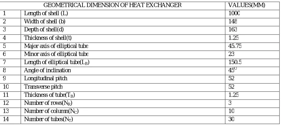
Total 30 tubes of 3 row and 10 column inline arrangement with longitudinal and transverse pitch of 52 mm are drawn. Then solid tubes with same dimensions with length 150 mm are created using extrude command. Finally assembled both the shell and tube. Table 3.1 shows the geometric dimensions of cross flow heat exchanger.
Table 3.1 Geometric Dimensions of Cross Flow Heat Exchanger
GEOMETRICAL DIMENSION OF HEAT EXCHANGER VALUES(MM)
1 Length of shell (L) 1000
2 Width of shell (b) 148
3 Depth of shell(d) 163
4 Thickness of shell(t) 1.25 5 Major axis of elliptical tube 45.75 6 Minor axis of elliptical tube 23 7 Length of elliptical tube(LB) 150.5
8 Angle of inclination 45O
9 Longitudinal pitch 52
10 Transverse pitch 52
11 Thickness of tube(TB) 1.25
12 Number of rows(NR) 3
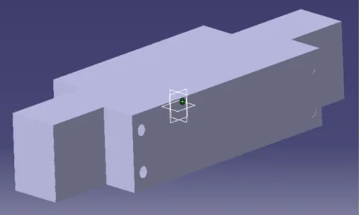
Fig 3.1 shows the shell of cross flow heat exchanger.
Figure 3.1 Shell of Cross Flow Heat Exchanger
Fig 3.2 shows the elliptical tube of cross flow heat exchanger.
Figure 3.2 Elliptical Tube of Cross Flow Heat Exchanger.
Fig 3.3 shows the assembly of cross flow heat exchanger.
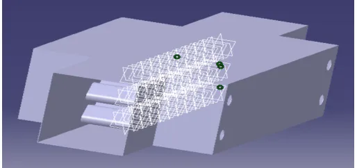
Fig. 3.4 shows cross flow heat exchanger for 3D CFD simulation.
Figure 3.4 Cross Flow Heat Exchanger For 3D CFD Simulation
Mesh
Meshing of heat exchanger is done in ANSIS Workbench Design Module. It is cross flow heat exchanger. First, the fluid flow (fluent) module from the workbench is selected. The design modeller opens as anew windows as the geometry is double click. Then the geometry which is in IGES format is imported from stored file. Then double click on mesh, the meshing window opens.
Initially a relatively coarse mesh is generated. This mesh contains mixed cells having both triangular and quadrilateral elements. To improve the meshing we have applied following steps:
i. Automatic method
Method – Quadrilateral Dominant Element – First order (linear) Free face mesh type – Quad/ Tri
ii. Sizing
Element size – 2 mm Size function – uniform Behaviour – soft Growth rate – 1.2
iii. Inflation
Inflation option – smooth transition Transition ratio – 0.5
Maximum layers – 6 Growth rate – 1.2
iv. Named Selection
1. Inlet 2. Outlet
3. Boundary Wall 4. Tube Wall
After meshing the quality of meshing is checked. In that the following parameters related to quality of mesh were found: i. Skewness – 0.62902 (Max)
ii. Aspect ratio – 5.2636 (Max) iii. Jacobian ratio – 4.7954 (Max)
From meshing number of nodes and elements are as follows: Nodes – 46609
Elements – 45276
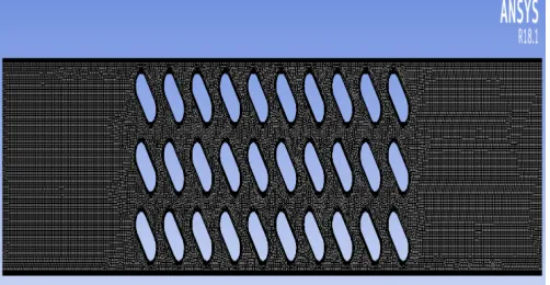
Fig. 3.5 shows 2D mesh of flow domain.
Figure 3.5 2D Mesh of Flow Domain
Fig. 3.6 shows mesh structure near tube wall.
Solution
After generation of meshing double click on setup new window of fluent solver opens.
Problem Setup
The mesh is checked and quality is obtained. The analysis type is changed to the pressure based type. The velocity formulation is changed to the absolute and time to steady state. Gravity is defined as y= -9.81 m/sec2
Models
Energy is set to on position. The flow is turbulent so realisable k-epsilon is selected in viscous model.
Materials
Create / edit option is clicked to add air and steel to the list of fluid and solid respectively from fluent data base.
Air properties
Density – 1.225 kg/m3
Specific Heat – 1006.23 J/kgK Thermal Conductivity – 0.0242 W/mk Viscosity – 1.7894e-5 kg/m-sec
Steel properties
Density – 8030 kg/m3 Specific Heat – 502.48 J/kgK Thermal Conductivity – 16.27 W/mk
Cell Zone Condition
The part are assigned as air and steel as per fluid/ solid part.
Boundary Condition
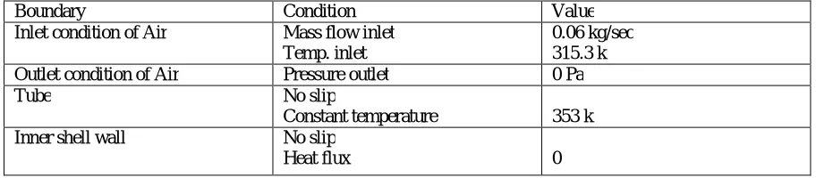
Boundary conditions are used according to the need of the model. The inlet and outlet conditions are defined as mass flow inlet and pressure outlet. The tube wall and shell wall are separately specified with boundary condition. The details about all boundary conditions can be seen in given below. Table 3.2 shows the boundary conditions.
Table 3.2 Boundary conditions
Boundary Condition Value Inlet condition of Air Mass flow inlet
Temp. inlet
0.06 kg/sec 315.3 k Outlet condition of Air Pressure outlet 0 Pa Tube No slip
Constant temperature 353 k Inner shell wall No slip
Reference values
The inner inlet is selected from drop down list of “Compute from”. The values are:
Area – 1 m2
Density – 1.225 kg/m3
Depth – 1 m
Enthalpy – 100125.6 J/kg
Length – 1 m
Pressure – 0 Pa
Temperature – 315.3 k
Velocity – 0.3004883 m/s
Viscosity – 1.7894e-5 kg/m-sec
Ratio of specific heat – 1.4
Solution Method
The solution methods are specified as follows:
Scheme - simple
Gradient – least square cell base
Pressure – second order
Momentum – second order upwind
Turbulent kinetic energy – 1st order upwind
Turbulent dissipation rate – 1st order upwind
Energy – 2nd order upwind
Solution Control and Initialization
Under relaxation factors the parameters are
Pressure – 0.3 Pa
Density – 1 kg/m3
Body forces – 1 kg/m2sec2
Momentum – 0.7 kg-m/sec
Turbulent kinetic energy – 0.8 m2/s2
Turbulent dissipation rate – 0.8 m2/s3
Then the solution initialization method is set to hybrid initialization.
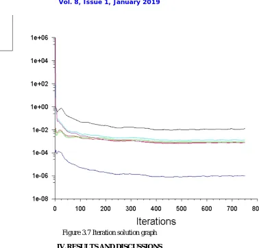
Run Calculation
Figure 3.7 Iteration solution graph
IV.RESULTSANDDISCUSSIONS
In results and discussion various contours, vectors, plots related to temperature, pressure, velocity and results of simulation are discussed.
Results from CFD
Contours
Fig 4.1 shows the temperature distribution in Kelvin
Figure 4.1 Contours of temperature distribution in K
Fig 4.2 shows the velocity distribution in m/sec
Fig 4.3 shows pressure distribution in Pascal
Figure 4.3 Contours of pressure distribution in Pascal
Vectors
Fig. 4.4 shows the velocity vector distribution (m/sec)
Figure 4.4 Velocity vectors coloured by velocity magnitude (m/s)
Fig. 4.5 shows close view of eddies formation by velocity vector
Figure 4.5 Close view of eddies formation by velocity vector
Plots
Fig. 4.6 shows the variation of Reynold’s Number with the temperature difference of air for various cases.
Figure 4.6 Reynolds number vs temperature difference of air
0 5 10 15 20 25 30
0 5000 10000 15000 20000 25000
TE
M
P
ER
A
TU
R
E
RE
Fig 4.7 shows variation of Reynold’s Number with heat transfer coefficient for various cases.
Figure 4.7 Reynolds Number vs Heat Transfer Coefficient
Fig 4.8 shows graph of variation of Reynold’s Number vs Nusselt Number
Figure 4.8 Reynolds Number vs Nusselt Number
0 20 40 60 80 100 120 140 160 180 200
0 5000 10000 15000 20000 25000
H E AT T R AN SF ER C O E FF IC IE N T REYNOLD NUMBER
ha(CFD) ha(Expt.) Linear (ha(CFD)) Linear (ha(Expt.))
0 1 2 3 4 5 6
8.8 9 9.2 9.4 9.6 9.8 10 10.2
LO G( N U ) LOG(RE) ln(Nu)Elliptical ln(Nu)Circular
CFD Calculations
Sample Calculation for reading 1 Water side calculation
Given data
Flow rate of water (Mw) constant = 1400 LPH Water inlet temperature T1 = 80oC
Water outlet temperature T2 = 80oC
Average mean temperature of water at inlet and outlet = 80oC Properties at 80oC
Density of water = 971.8 kg/m3
Thermal conductivity of water K = 0.67 W/mok Dynamic viscosity of water µ = 3.55 × 10⁻⁴ N-sec/m2 Prandlt Number of water Pr = 2.22
H1 = 0.025 m V2 = 0.02075 m
Formula
DittusBoelter Equation
Nuw = 0.023 Re0.8 Pr0.3 (1) Hydraulic diameter (Dh)w= (2) Three Tube c/s area Ac/s(tube) = 3 ( × (V2)2 + V2 × H1 ) (3) Velocity of water
(V)w = × (4)
Reynolds Number of water
(Re)w= (5)
Heat transfer coefficient of water hw =
×
(6)
Calculations
(Dh)w = 0.029 m ….From (2)
Ac/s(tube) = 2.58×10⁻³ m2 ….From (3)
(V)w = 0.155 m/sec ….From (4) (Re)w= 1.23 × 10⁴ ….From (5)
Nuw= 54.8 ….From (1)
hw = 1270 W/m2k ….From (6)
Air Side Calculations
Given data
Mass flow rate of air, Ma = 0.06 kg/sec Inlet temperature of air T3 = 315.3 ok Outlet temperature of air T4 = 339.022 ok Properties of air at mean temperature Specific heat of air (Cp)air = 1.00808 kJ/kg-k Number of tubes NT = 30
Density of Air = 1.085 kg/m3 Specific heat of air (Cp)air= 1.0080 kJ/kg-k Dynamic viscosity of air µair = 202.76×10⁻⁷ N-sec/m2 Kinematic viscosity = 19.762 × 10⁻⁶
m2/sec Thermal conductivity of air Kair= 28.31×10⁻³ W/mok Prandlt Number Pr=0.70319
Formula
Tube Length Surface Area (Ats) =(π × V3+ 2 × H1) × H4 × NT (7) Side plate surface area (Aps) = 2 [V6 × F - ( × V3 + V3 × H1 ) × NT] (8)
Average temperature, Tm = (9) Heat transfer area = Tube length surface area + Side plate surface area
(As) = (Ats) + (Aps) (10) Heat absorbed by Air (Q)
Q = MaCp (T4 - T3) (11) Log Mean Temperature Difference (LMTD)
LMTD = ( ) ( )
( ) (12)
Overall heat transfer coefficient (U ) U =
× (13)
Heat transfer coefficient of Air (ha)
= + (14)
Nusselt number of Air for Elliptical tube ( Nu ) (Nu)elliptical=
×( )
(15)
Velocity of air = × (16)
Minimum area for air flow
Amin = H4× [V6−(3 45 × )] (17)
Reynold number for air
(Re)air= (18)
Zukauskas Equation
(Nu)circular= 0.27(Re)0.63( Pr)0.36 (19)
Heat transfer coefficient of air from circular correlation (h)circular=
×
(20)
Enhancement Ratio = (21)
Calculations
Tm = 327.161 k ….From (9) (As) = (Ats) + (Aps) ….From(10) = 0.55016 + 0.15247
= 0.7026 m2
Q = 1434.699 W ….From (11) LMTD = 23.909 ….From (12)
U = 85.406 w/m2k ….From (13)
(ha)elliptical= 91.56 w/m2k ….From(14)
(V)air= 5.349 m/sec ….From(16) (Re)air= 9273.95 ….From(18)
(Nu)circular= 75.1080 ….From(19)
(h)circular= 65.628 w/m2k ….From(20)
Enhancement Ratio = 1.395 ….From (21)
Result of CFD Analysis and Experimental Investigation
Table 4.1 shows the variation of Mass flow rate, Inlet Temperature of Water, Outlet Temperature of Water, Inlet Temperature of Air, Outlet Temperature of Air, Overall heat transfer coefficient and Heat transfer coefficient of elliptical and circular tube from CFD Analysis.
Table 4.1 Observations and Results from CFD Analysis
Sr. No. ma kg/sec T1 (ok)
T2 (ok)
T3 (ok)
T4 (ok)
U W/m2k
(ha)ellip. W/m2k
(ha)cir. W/m2k
1 0.06 353 353 315.3 339.0 85.4 91.56 65.62 2 0.069 353 353 315.7 338.1 90.95 97.97 72.17 3 0.078 353 353 315 337.82 102.70 111.74 77.94 4 0.088 353 353 316.4 336.3 127.68 141.95 84.32 5 0.108 353 353 311.9 335.20 129.68 144.41 95.49 6 0.119 353 353 312.9 334.61 113.46 149.14 102.52 7 0.123 353 353 312.9 335.03 141.62 159.39 105.14 8 0.049 353 353 316.9 341.85 82.69 88.40 55.08 9 0.095 353 353 317.1 337.57 115.10 126.57 88.37 10 0.111 353 353 315.3 337.37 140.25 157.66 98.58 11 0.128 353 353 315.9 336.56 152.19 172.82 110.9 12 0.117 353 353 316.4 337.20 141.04 158.68 101.97 13 0.058 353 353 319.0 340.88 85.91 92.14 64.9 14 0.105 353 353 310 334.9 128.39 142.83 124.1 15 0.116 353 353 311.5 335.19 140.82 158.46 101.07
Table 4.2 Observations and Results from CFD Analysis
Sr. No. (Nu)ellip. (Nu)cir. (Re)a
ℎ .
ℎ .
(Pr)a (Re)w (Nu)w (Pr)w
1 103.49 75.1 9273.9 1.395 0.7032 12304.90 54.8 2.22 2 110.8 82.66 10796.8 1.35 0.7032 12304.90 54.8 2.22 3 126.6 89.39 12225.5 1.51 0.7033 12304.90 54.8 2.22 4 161.24 96.97 13909.4 1.68 0.0734 12304.90 54.8 2.22 5 164.78 110.34 17069.84 1.512 0.7037 12304.90 54.8 2.22 6 170.09 118.38 19087.66 1.45 0.7036 12304.90 54.8 2.22 7 181.71 119.86 19468.91 1.51 0.7036 12304.90 54.8 2.22 8 99.23 66.01 7558.61 1.52 0.7028 12304.90 54.8 2.22 9 143.01 101.1 14864.5 1.432 0.7031 12304.90 54.8 2.22 10 167.45 111.71 17414.2 1.59 0.7033 12304.90 54.8 2.22 11 195.94 125.67 20993.65 1.559 0.7033 12304.90 54.8 2.22 12 179.54 115.38 18333.66 1.55 0.7032 12304.90 54.8 2.22 13 103.41 73.54 8973.03 1.41 0.7028 12304.90 54.8 2.22 14 163.17 108.44 16605.4 1.317 0.7038 12304.90 54.8 2.22 15 180.90 115.41 18331.1 1.567 0.7037 12304.90 54.8 2.22
Table 4.3 shows the variation of Mass flow rate, Inlet Temperature of Water, Outlet Temperature of Water, Inlet Temperature of Air, Outlet Temperature of Air, Overall heat transfer coefficient and Heat transfer coefficient of elliptical and circular tube from Experimental Results.
Table 4.3 Observations and Results from Experimental Investigation
Sr. No. ma kg/sec T1 (ok)
T2 (ok)
T3 (ok)
T4 (ok)
(ha)ellip. W/m2k
(ha)cir. W/m2k
(Nu)cir.
Table 4.4 shows Nusselt Number values for elliptical tube, circular tube, Reynolds number in air, ratio of heat transfer coefficient of elliptical tube and circular tube, Prandtl Number in air, Reynold’s Number in Water, Nusselt Number in Water and Prandtl Number in Water using Experimental Investigation.
Table 4.4 Observations and Results from Experimental Investigation
V. CONCLUSION
1. A CFD package (Ansys Fluent 18.1) was used for the numerical study of heat transfer characteristics of an elliptical shaped tube blank in cross flow heat exchanger and the results were validated with experimental results. The CFD results when compared with experimental results for different mass flow rate and were well within the error limits of 30 to 40%.
2. Temperature distribution contours showed that the percentage of error of outlet temperature of air from validation of CFD result with experiment is 2 to 3 %.
3. The enhancement ratio of elliptical shaped tube blank is 1.3 to 1.7 range compare to circular shaped tube blank in 9273.9 to 21000 Reynolds number range.
4. CFD analysis of model and velocity vectors showed that due to use of elliptical shaped tube blank at 45o angle of attack is delayed the boundary layer separations and it also reduce wake region formation compared to circular shape tube.
5. Velocity vector contours showed that due to orientation of tube blanks at 45o better mixing of air flow which enhance large heat transfer rate compare to 00 orientation of tube blanks.
6. The pressure distribution contours showed that reduced pressure drop due to eddies formation. But overall effect is to enhance the heat transfer rate.
Sr. No. ma kg/sec (Re)a
ℎ .
ℎ .
(Pr)a (Re)w (Pr)w (Nu)w
REFERENCES
[1] S. Toolthaisong N Kasayapanand, “Effect of attack angles on side thermal and pressure drop of the cross flow heat exchnagers with staggered tube arrangement”, Energy Procedia 34 (2013) 417 – 429.
[2] Talaat A Ibrahim, AbdallGomma, “Themal performance criteria of elliptic tube bundle in crossflow”, International Journal of Thermal Science 48 (2009) 2148 – 2158.
[3] X.P. Du a, M. Zeng, “Experimental study of the effect of air inlet angle on the air side performance for cross flow finned oval tube heat exchangers”, Experimental Thermal and Fluid Science 52 (2014) 146 – 155.
[4] Lie Sun, Liang Yang, Liang Shao, “Overall thermal performance oriented numerical comparison between elliptical and circular finned tube condenser”, International Journal of Thermal Science 89 (2015) 234 - 244.
[5] Hui Han, Ya-Ling He, Yin-Shi Li, “A numerical study on compact enhanced fin and tube heat exchanger with oval and circular tube configurations”, International Journal of Heat and Mass Transfer 65 (2013) 686 – 695.
[6] Ala Hasan, Kai Siren, “Performance investigation of plain circular and oval tube evaporatively cooled heat exchangers”, Applied Thermal Engineering; Vol. 24 (2014) 777 – 790.
[7] ArashMirabdolahLavasani, HamidrezaBayat, TaherMaarefdoost, “Experimental study of convective heat transfer from in-line cam shaped tube bank in crossflow”, Applied Thermal Engineering 65 (2014) 85 – 93.
[8] Mesbah G. Khan, Amir Fartaj, David S.K. Ting, “An experimental characterization of cross flow cooling of air via an in-line elliptical tube array”, International Journal of Heat and Fluid Flow 25 (2004) 636 – 648.
[9] Cengel, Y.A. and Ghajar A. J., Heat and Mass Transfer 5th edition, Tata McGraw Hill, 446 – 450.
[10] ShelarDigvijay, “Experimental Investigation of Elliptical Tube Bank Cross Flow Heat Exchanger with Inline Arrangement and 45o Angle of Attack”, Dept. of Mechanical Engineering, (2015-16).
VI.NOMENCLATURE
T1 Inlet temperature of water (k) T2 Outlet temperature of water (k) T3 Inlet temperature of air T4 Outlet temperature of air
ṁ Mass flow rate (kg/sec)
ρ Density (kg/m3) L Length of duct (m) B Width of duct (m)
D Diameter of semi-circular portion of tube (m) T Thickness of tube (m)
Dhi Inside hydraulic diameter of tube (m) Dho Outside hydraulic diameter of tube (m) Nr Number of rows
Nc Number of column
Ac Cross sectional area of tube (m2) As Heat transfer surface area (m2) Cp Specific heat (kJ/kg K) K Thermal conductivity (w/m K)
K Turbulence kinetic energy (m2/s2) Turbulence dissipation rate (m2/s3)
Dynamic viscosity (kg/ms) Kinematic viscosity (m2/s) Pr Prandtl number
Re Reynolds number Nu Nusselt number
∆T Temperature Difference (oC) Q Heat transfer (W)
Subscripts