Apple Computer, Inc.
This manual and the software described in it are copyrighted, with all rights reserved. Under the copyright laws, this manual or the software may not be copied, in whole or part, without written consent of Apple, except in the normal use of the software or to make a backup copy of the software. The same proprietary and copyright notices must be affixed to any permitted copies as were affixed to the original. This exception does not allow copies to be made for others, whether or not sold, but all of the material purchased (with all backup copies) may be sold, given, or loaned to another person. Under the law, copying includes
translating into another language or format.
You may use the software on any computer owned by you, but extra copies cannot be made for this purpose. The Apple logo is a registered trademark of Apple Computer, Inc. Use of the “keyboard” Apple logo (Option-Shift-k) for commercial purposes without the prior written consent of Apple may constitute trademark infringement and unfair competition in violation of federal and state laws.
©Apple Computer, Inc., 1993 20525 Mariani Avenue Cupertino, CA 95014-6299 (408) 996-1010
Apple, the Apple logo, APDA, AppleLink, AppleShare, AppleTalk, EtherTalk, LaserWriter, LocalTalk, Macintosh, MacTCP, and TokenTalk are registered trademarks of Apple Computer, Inc.
MacSNMP is a trademark of Apple Computer, Inc.
Adobe, Adobe Illustrator, and PostScript are trademarks of Adobe Systems Incorporated, which may be registered in certain jurisdictions.
CompuServe is a registered service mark of CompuServe, Inc. DEC is a trademark of Digital Equipment Corporation. Electrocomp 2000 is a trademark of Image Graphics Inc.
Hewlett-Packard is a registered trademark, and HP is a trademark, of Hewlett-Packard Company. IBM is a registered trademark of International Business Machines Corporation.
ITC Zapf Dingbats is a registered trademark of International Typeface Corporation. NuBus is a trademark of Texas Instruments.
Sun is a trademark of Sun Microsystems, Inc.
UNIX is a registered trademark of UNIX System Laboratories, Inc. Simultaneously published in the United States and Canada.
Preface
About This Guide / ix
Intended audience / ix How to use this guide / x
Conventions / x Associated documents / xi
Books / xi
Request for Comments (RFC) / xii Military standards / xii
Part 1 Concepts / 1
1
About the MacTCP Driver / 3
Overview / 4
System requirements / 5 Network environment / 6 DDP-IP gateway / 7
2
About TCP/IP / 9
The family of protocols / 10 Internet Protocol (IP) / 12
Transmission Control Protocol (TCP) / 12 User Datagram Protocol (UDP) / 13
Telnet / 13
File Transfer Protocol (FTP) / 13
Simple Mail Transfer Protocol (SMTP) / 14
Simple Network Management Protocol (SNMP) / 14
3
TCP/IP Addressing Conventions / 15
Internet addresses / 16 Subnetwork addressing / 17 Subnetwork masks / 19 The domain name system / 19
Address Resolution Protocol (ARP) / 21
Reverse Address Resolution Protocol (RARP) / 22 Bootstrap Protocol (BootP) / 23
4
Routing / 25
Gateways / 26 Routing tables / 27 Routing protocols / 27
Routing Information Protocol (RIP) / 27 Internet Control Message Protocol (ICMP) / 28
Part 2 Procedures / 29
5
Configuring MacTCP / 31
The MacTCP Admin and MacTCP files / 32 Configuration tools in MacTCP Admin / 32
The MacTCP control panel / 32 The Administrator dialog box / 33
Obtain Address box / 34 IP Address box / 34
Routing Information box / 34
Domain Name Server Information box / 35 Protected checkbox / 35
Configuration scenarios / 35
Opening the MacTCP control panel / 38 Version 7.x environment / 38
Version 6.0.x environment / 39 Setting link level information / 40
Network configuration 1 / 41 Network configuration 2 / 42 Network configuration 3 / 43 Network configuration 4 / 44 Network configuration 5 / 46 Adjusting the MTU size / 48
Setting the IP address in decimal notation / 50 Opening the Administrator dialog box / 51 Setting the IP address / 52
Setting the address manually / 53
Setting the IP address class / 53 Setting the subnet mask / 55
Setting the IP address (integer format) / 55
Obtaining an address from a server / 57 Setting the node number dynamically / 58 Setting the gateway address / 59
Setting domain name server information / 59 Domain Name Resolver (DNR) operation / 60 Protecting the configuration / 61
Giving the user full configuration power / 61 Closing the control panel / 62
What to do next / 62
6
Distributing the TCP/IP Connection Software / 63
Before you distribute the software / 64 The MacTCP Prep configuration rules / 64
Giving the MacSNMP Client application to the user / 64 User documentation / 65
Distribution media / 65
Distributing MacTCP only—any media / 66
Distributing a MacTCP startup disk—version 6.0.x only / 67 Distributing the TCP/IP Connection software on floppy disks / 68 Distributing the TCP/IP Connection software over the network / 69
Part 3 Appendixes / 71
Appendix A
Name-to-Address Mapping / 73
Hosts file syntax / 74 Editing the Hosts file / 75
Appendix B
Troubleshooting / 77
Duplicate address notification / 78 MacTCP Ping / 78
MacTCP Ping menus / 79
File / 79 Edit / 79 Options / 79
MacTCP Ping Information dialog box / 80
Ping Host Address / 80 Send ASCII/Hex Data / 80 Packet Data Size / 80
Send a packet every # ticks / 81 Display / 81
Start Ping / 81 Stop Ping / 81
Information and statistics area / 81
Glossary / 83
Index / 87
Figure 1-1 A MacTCP network configuration / 6 Figure 2-1 An internet / 10
Figure 2-2 A comparison of OSI and TCP/IP / 11 Figure 3-1 An IP address structure / 17
Figure 3-2 Subnetting at Pundit University / 18 Figure 4-1 Gateways connecting networks / 26
Figure 5-1 A view of the MacTCP control panel in version 6.0.x / 33 Figure 5-2 A view of the MacTCP Admin panel, the MacTCP control panel in
version 7.x / 33
Figure 5-3 A view of the Administrator dialog box / 33 Figure 5-4 A road map to configuration scenarios / 37
Figure 5-5 Multiple Token Ring cards in a Macintosh II computer, as seen in the Token Ring and MacTCP control panels / 47
Figure 5-6 Physical slot numbers (shaded) and NuBus slot numbers in various Macintosh computers / 48
Table 3-1 The top-level domains / 20
This guide describes the MacTCP driver, Apple Computer’s implementation of the protocol suite known as Transmission Control Protocol/Internet Protocol (TCP/IP). It contains theoretical information about the protocol suite as well as instructions for configuring MacTCP. This guide is one of four documents that you received with your TCP/IP Administration product:
■ TCP/IP Administration: Overview and Installation ■ MacTCP Administrator’s Guide
■ MacSNMP Administrator’s Guide ■ TCP/IP Connection User’s Guide
The TCP/IP Administration: Overview and Installationguide describes how to install the MacTCP software, then directs you to this manual for instructions on configuring the software for your computer and for some or all of your users.
Intended audience
This guide is intended for the network administrator who is responsible for network configuration. You should be familiar with Macintosh computer operations and general networking concepts. However, it is not necessary to be a TCP/IP expert; Part 1 of this guide provides conceptual information if you need to learn more about TCP/IP.
Preface
About This Guide
The major part of administering a MacTCP network involves using the MacTCP Admin control panel to configure MacTCP for network users. Before you start, you must determine how much you want network users involved in the configuration process; for instance, you can set up the control panel so that the user must enter all the
configuration information or none of it. See the section “Configuration Scenarios” in Chapter 5 for more information.
How to use this guide
This guide begins with basic concepts in Part 1 and proceeds to explicit instructions in Part 2. It is important to understand TCP/IP concepts, such as IP addressing, to configure the system correctly. To learn these basics, read the chapters in Part 1. If you are already familiar with TCP/IP, you may decide to move quickly to Part 2.
Part 2 describes how you, as a network administrator, configure the MacTCP driver and then distribute the TCP/IP Connection software to network users who in turn install and configure the software for their individual machines.
Conventions
The following conventions are used in this guide:
■ 6.0.x refers to system software version 6.0.5 or later, but not version 7.0. ■ 7.x refers to system software version 7.0 or later.
◆ Note Text set off in this manner presents sidelights or interesting points of information. ◆
s Important Text set off in this manner—with the word Important—presents information that you must consider as you read the surrounding text. s
Associated documents
For additional information about MacTCP networks, see the MacTCP Programmer’s Guide. This guide is for third-party developers creating application programs for the MacTCP driver. The MacTCP Programmer’s Guide is available from APDA. That address is
APDA
Apple Computer, Inc. P.O. Box 319
Buffalo, NY 14207-0319 U.S.A. 800-282-2732 (United States) 800-637-0029 (Canada) 716-871-6555 (International) Fax: 716-871-65111
AppleLink: APDA
CompuServe: 76666,2405
Internet: [email protected]
You might also find it useful to refer to Inside AppleTalk, Second Edition for a complete description of the AppleTalk network system.
Books
The following books provide information on TCP/IP:
■ An Introduction to TCP/IP,by John Davidson, Springer-Verlag.
■ Handbook of Computer-Communication Standards, Volume 3: Department of Defense
(DOD) Protocol Standards,by William Stallings, Macmillan Publishing Company.
■ Internetworking With TCP/IP—Principles, Protocols, and Architecture, Second
Edition, by Douglas Comer, Prentice-Hall.
Request for Comments (RFC)
Request for Comments (RFC) is a series of technical notes used by the Internet community that contains reports of work, proposals, and protocol specifications. Important RFCs include 768 (UDP), 791 (IP), 792 (ICMP), 793 (TCP), 826 (ARP), 903 (RARP), and 951 (BootP). RFCs 999, 1000, and 1012 provide a guide to RFCs. RFC 1011 lists the official protocols.
RFCs are available from the DDN Network Information Center (NIC) at SRI International. That address is
DDN Network Information Center SRI International, Room EJ 291 333 Ravenswood Avenue Menlo Park, CA 94025
You can order hard copies of RFCs by calling 415-859-3695. To obtain an RFC
electronically over the Internet, use anonymous FTP from the <RFC> directory on host SRI-NIC.ARPA. If you are outside the Internet and don’t have access to FTP, you can receive RFCs by sending electronic mail to [email protected]. Put the RFC number in the “Subject:” field.
The DDN NIC publishes the DDN Protocol Handbook, which contains most important RFCs related to TCP/IP.
Military standards
The Internet Protocol (IP), Transmission Control Protocol (TCP), File Transfer Protocol (FTP), Telnet, and Mail are described in the five Military Standards (MIL-STD) about TCP/IP protocols. These standards contain errors; when there are discrepancies between MIL-STDs and RFCs, RFCs always take precedence. You can obtain MIL-STDs from
Defense Printing Service Detachment Office Building 4D
700 Robbins Avenue Philadelphia, PA 19111-5094 Fax: 215-697-2978
The MacTCP driver, Apple Computer’s TCP/IP product, increases the Macintosh
computer’s ability to operate in a heterogeneous computer environment. MacTCP
software allows the Macintosh computer to communicate with such diverse systems as
IBM, DEC™, Sun, and Hewlett-Packard computers. This chapter describes the features
and operation of the MacTCP driver.
Overview
The MacTCP driver is a software driver for the Macintosh Operating System that implements the following TCP/IP protocols:
■ Internet Protocol (IP)
■ Internet Control Message Protocol (ICMP)
■ User Datagram Protocol (UDP)
■ Address Resolution Protocol (ARP)
■ Reverse Address Resolution Protocol (RARP)
■ Routing Information Protocol (RIP)
■ Bootstrap Protocol (BootP)
■ Transmission Control Protocol (TCP)
These protocols provide core transmission services that third-party products use such as electronic mail, remote login, file transfer, remote printing, database access, and network management. Chapters 2, 3, and 4 describe these protocols and the services they provide.
The MacTCP driver conforms to Internet Request for Comments (RFC) and Military Standards (MIL-STD), ensuring interoperability with systems on the internets operated by local and regional network providers.
The network administrator uses the MacTCP Admin control panel to configure the MacTCP driver, thus simplifying installation and setup procedures. Chapter 5 of this guide describes how to use the MacTCP Admin control panel to configure the driver.
The MacTCP driver includes these features:
■ A driver-level interface that allows the implementation of application protocols such as the File Transfer Protocol (FTP), SNMP, and Telnet.
■ A domain name resolver that maps domain names to internet addresses. The domain name resolver is compatible with domain name server implementations that comply with RFC 1034 and 1035.
■ A dialog box notification of the occurrence of a duplicate address.
System requirements
To use the TCP/IP Connection product, you need the following hardware and software:
■ On a LocalTalk network, you need a Macintosh Plus computer or later model connected to the LocalTalk cable.
■ On an Ethernet network, you need a Macintosh Plus computer or later model with an Ethernet connection such as the EtherTalk NB Card, Ethernet NB Card, a built-in Ethernet interface, or a third-party Ethernet device. Apple Ethernet connections require EtherTalk software version 2.5 or later. Third-party Ethernet devices must be compatible with the MacTCP driver.
■ On a Token Ring network, you need a Macintosh computer that uses the NuBus™ expansion slot architecture, such as one of the Macintosh II family of computers, and an appropriate networking card, such as the TokenTalk NB Card, the Token Ring 4/16 NB Card, or a third-party Token Ring card that supports the .TOKN interface
specification. Apple Token Ring connections also require TokenTalk Phase 2 and TokenTalk Prep software, version 2.5 or later (the software for the Token Ring card) and the MacTCP Token Ring Extension software contained in this product. Third-party Token Ring cards must be compatible with Apple Computer’s MacTCP Token Ring Extension software, or the manufacturer must provide its own extension software that is compatible with the MacTCP driver.
■ To use the AppleTalk encapsulation feature of MacTCP to connect to systems outside of the AppleTalk internet, the AppleTalk network must contain a Datagram Delivery Protocol-Internet Protocol (DDP-IP) gateway.
■ To use MacTCP software, you need system software version 6.0.5 or later, or system software version 7.0 or later.
■ To use the MacSNMP software, you need system software version 7.0 or later, 4 megabytes (MB) of RAM, and an SNMP console that supports TCP/IP.
s Important The TCP/IP Connectiondisk is a high-density disk. You need a high-density floppy disk drive to read this disk. s
Network environment
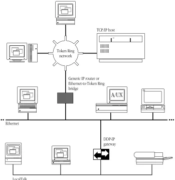
The MacTCP driver runs over LocalTalk, Ethernet, and Token Ring–compatible cable systems, as shown in Figure 1-1. A Macintosh Plus computer or later model can run the MacTCP driver.
The MacTCP driver is co-resident with AppleTalk protocols so that there can be concurrent TCP/IP and AppleTalk operation. For example, you could download a file with FTP while a print job is being sent to an Apple LaserWriter printer over LocalTalk cable. AppleTalk and MacTCP software can run over the same medium, or one protocol can run over one medium while another protocol runs over a different medium.
Figure 1-1 A MacTCP network configuration
Ethernet
Token Ring network
A/UX Generic IP router or
Ethernet-to-Token Ring bridge
TCP/IP host
DDP-IP gateway
LocalTalk
DDP-IP gateway
To run MacTCP software on LocalTalk cable (or any other AppleTalk-compatible media), you need a Datagram Delivery Protocol-Internet Protocol (DDP-IP) gateway. This device takes a TCP/IP packet that is encapsulated in DDP, an AppleTalk protocol, and converts it to an Ethernet format. DDP-IP gateways can also assign addresses to MacTCP nodes and manage routing to other networks.
If the MacTCP software is running on LocalTalk, a DDP-IP gateway must be provided on the network as shown in Figure 1-1. By default, the DDP-IP gateway should be located in the same AppleTalk zone as the Macintosh computer running the MacTCP software. Alternatively, a single DDP-IP gateway can support Macintosh computers in multiple AppleTalk zones; in this case, the user must select the zone where the DDP-IP gateway resides, using the MacTCP control panel. It is further recommended that the user select server-based addressing when configuring the MacTCP driver.
The Transmission Control Protocol/Internet Protocol (TCP/IP) is a widely used industry
standard for connecting multivendor computers. The TCP/IP protocol layers are fully
compatible across all implementations on different hardware platforms, allowing different
vendors’ computers that run TCP/IP to interoperate and share data and services.
TCP/IP development began when the Defense Advanced Research Projects Agency
(DARPA) decided there was a need for more reliable communication protocols on the
ARPANET, its packet-switched wide area network. DARPA initiated a research project to
define and implement a suite of protocols, and the researchers developed TCP/IP.
Eventually TCP/IP became the standard protocol suite used on the DARPA Internet, a
collection of networks that includes the ARPANET, Military Network (MILNET), National
Science Foundation Network (NSFnet), and networks at universities, research institutions,
commercial institutions, and military installations. Since then, hundreds of vendors have
developed products that support TCP/IP, and many different networks use it.
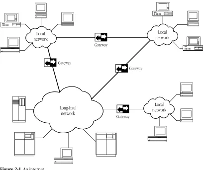
TCP/IP supports an architecture of multiple networks interconnected by gateways. This
interconnected set of networks is called an internetwork or internet. Figure 2-1 shows an
example of an internet. For example, TCP/IP protocols can be used to connect networks
on a college campus as well as geographically distant sites on a wide area network.
Figure 2-1 An internet
The family of protocols
TCP/IP is a family of protocols named after the fundamental protocols in the suite, the Transmission Control Protocol (TCP) and the Internet Protocol (IP). The protocols described in this guide are the ones most commonly supported by computers attached to TCP/IP networks.
Gateway
Gateway
Gateway
Gateway Long-haul
network
Local network
Local network Local
network
TCP, IP, and the User Datagram Protocol (UDP) provide basic transmission facilities that are augmented by application services in higher-level protocols such as Telnet, the File Transfer Protocol (FTP), the Simple Mail Transfer Protocol (SMTP), and the Simple Network Management Protocol (SNMP).
SNMP and Apple’s implementation of the protocol, MacSNMP, are discussed in detail in the MacSNMP Administrator’s Guide.
Other protocols in the TCP/IP family are described in later chapters of this guide. The Address Resolution Protocol (ARP), the Reverse Address Resolution Protocol (RARP), and the Bootstrap Protocol (BootP) are described in Chapter 3. The Routing Information Protocol (RIP) and the Internet Control Message Protocol (ICMP) are described in Chapter 4.
Although TCP/IP was designed and tested before the International Standards
Organization (ISO) defined the Open Systems Interconnection (OSI) Reference Model, it partially conforms to the OSI layers of networking functionality. Figure 2-2 shows a comparison of the OSI and the TCP/IP communications architecture. The TCP/IP protocols shown in Figure 2-2 are described in the following sections.
Figure 2-2 A comparison of OSI and TCP/IP
FTP Telnet SMTP
TCP UDP
IP
ALAP ELAP TLAP
LocalTalk Ethernet Token Ring Link Access Protocol
.MPP .ENET .TOKN driver
SCC Ethernet
card
Token Ring card
Developer products
SNMP Application Presentation Session Transport Network Data Link Physical MacTCP
OSI model TCP/IP
Internet Protocol (IP)
The Internet Protocol (IP) is responsible for sending data across multiple networks. IP accepts segments of data from TCP or UDP, places the data in packets called datagrams, and determines the correct path for the datagrams to take. The datagrams are sent across the internet, through as many gateways as needed, until they reach the destination host.
IP provides an addressing mechanism that allows routing between networks. The header of an IP datagram contains source and destination internet addresses so that any host in a network can route a packet to a destination, either directly or through a gateway.
IP has the ability to fragment a datagram as it is transmitted across a network. Since IP can be used with many different physical network implementations that specify different sizes for physical data frames, datagrams can be fragmented to fit into a smaller data frame. Fragments are reassembled as they arrive at the destination.
IP is often referred to as an unreliable delivery system because it makes a best-effort attempt to deliver all datagrams, but delivery is not guaranteed (TCP guarantees delivery). It is also called a connectionless delivery system because it routes each datagram
separately. When IP receives a sequence of datagrams from TCP or UDP, it routes each datagram in the sequence individually, and each datagram may travel over a different path to the destination.
Transmission Control Protocol (TCP)
The Transmission Control Protocol (TCP) provides reliable transmission of data between processes. (Processes are application programs that communicate; for instance, a file transfer process on one host talks to a file transfer process on another host.) It ensures that data is delivered error-free, without loss or duplication, and in sequence.
Upper-layer protocols such as Telnet pass data to TCP for delivery to peer processes. TCP encapsulates the data into segments and passes the segments to IP, which puts the segments into datagrams and passes them across the internet. TCP at the receiving end checks for errors, acknowledges error-free segments, and reassembles the segments for delivery to upper-layer protocols. If a segment is lost or damaged, it will not be
acknowledged, and the sending process will retransmit.
TCP has a flow-control mechanism so that computers of different speeds and sizes can communicate. When TCP at the receiving end sends an acknowledgment, it also
advertises how much data it is prepared to accept on the next transmission.
User Datagram Protocol (UDP)
The User Datagram Protocol (UDP) provides unreliable transmission of data between processes. The UDP transport of data is unreliable because, unlike TCP, it does not provide error checking, it does not acknowledge that data has been successfully received, and it does not order incoming messages. UDP messages can be lost, duplicated, or arrive out of order. Like TCP, UDP messages are encapsulated in IP datagrams for delivery.
The advantage of UDP is that the overhead associated with establishing and
maintaining an error-free TCP session is avoided. Upper-layer protocols that don’t require reliability use UDP to transmit data. For instance, the domain name system uses UDP because reliability is not critical; if there is no response to a domain name query, the resolver simply retransmits. (The domain name system is described in Chapter 3.)
Telnet
Telnet is a remote access protocol that allows a terminal on one host to appear as if it were directly connected to a remote host on an internet. Telnet also makes a personal computer act like a terminal. It is usually implemented as user software that initiates sessions to a remote location and server software that listens for connections from remote users.
File Transfer Protocol (FTP)
The File Transfer Protocol (FTP) is used to transfer files across an internet. A host can connect to a remote host on an internet and send or receive files, list directories, and execute simple commands. Like Telnet, FTP is usually implemented as user and server software. The user software interacts with the user at a host, and the server software receives requests from remote users to store or retrieve files.
Simple Mail Transfer Protocol (SMTP)
The Simple Mail Transfer Protocol (SMTP) transfers electronic mail messages from one host to another, across an internet. SMTP specifies the commands necessary to send mail and is used with a standard that specifies the general structure of a mail message.
Simple Network Management Protocol (SNMP)
The Simple Network Management Protocol (SNMP) is a widely accepted standard for managing devices on a multivendor network. An SNMP network management system consists of SNMP management software running on a computer called a consoleand SNMP agent software that is installed on each networked computer. The agents installed on a networked computer collect information—called variables—from the computer and relay this information to the management console.
MacSNMP is Apple Computer’s implementation of SNMP on the Macintosh. It provides the agent side of an SNMP network management system, allowing Macintosh computers on multivendor networks to be managed by third-party SNMP consoles.
For computers on the internet to refer to each other, each machine must be assigned a
universal address. This chapter describes the addressing scheme that was developed to
allow each TCP/IP host on the internet to be identified uniquely.
Internet addresses
Each host on a TCP/IP internet is assigned a unique 32-bit internet address (also called the
IP address). The address is divided into two fields, called the network fieldand the host field. The network field identifies a network on the internet to which the host attaches (so that all hosts on the same network share the same network field), and the host field identifies a particular host attached to that network.
The network field is assigned by a central authority, the Network Information Center (NIC). Local administrators assign the host field of the address. (Note that only networks that might attach to the DARPA Internet need to obtain the network address from the NIC.)
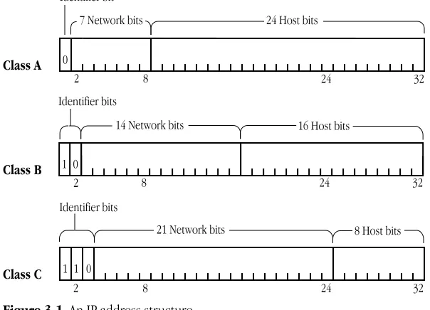
Three IP address classes—A, B, and C—provide for the following network configurations:
■ Class A addresses are used for a few networks with many hosts—for instance, the ARPANET.
■ Class B addresses are used for medium-sized networks—for instance, a university network.
■ Class C addresses are used for a large number of small networks—for instance, an Ethernet local area network (LAN).
The first bits of the address identify the address class, and the number of bits assigned to the network and host field of the address differs for each class. For instance, Class A addresses have 1 class identifier bit, 7 network identifier bits, and 24 host identifier bits. This allows for 128 Class A networks, where each network can support up to 16 million hosts. Figure 3-1 shows the class identifier bits and the number of bits allocated to the network and host fields for each address class.
To make the addresses easier to work with, they are written in dotted decimal notation. Each octet of the 32-bit address is assigned its decimal equivalent, and decimal points separate the integers.
For example, the 32-bit address 10000100 00001101 00000010 00011110 is written in dotted decimal notation as 132.13.2.30.
Figure 3-1 An IP address structure
Subnetwork addressing
The internet addressing scheme, designed for a few hundred networks, did not anticipate the proliferation of LAN technology. Organizations created large networks consisting of many LANs connected by gateways, and there was an explosive growth in the number of networks on the internet. Assigning every LAN on the internet its own network identifier created two problems:
■ Immense administrative overhead is required to manage the addresses.
■ Internet routing tables cannot accommodate many network addresses.
A technique called subnetwork addressing (or subnetting) was devised to deal with this problem. Subnetting allows multiple physical networks (called subnetworks) to share the same internet network number. For example, a university with two LANs can use subnet addressing so that both campus subnetworks share a single network number. The subnet structure is not visible to the rest of the internet; the route to the network is the same no matter what subnet the host is on.
Class A
Class B
Class C
Identifier bits
14 Network bits 16 Host bits
Identifier bits
21 Network bits 8 Host bits 32 Identifier bit
24 Host bits
0
2 8
7 Network bits
1 0
0 1 1
2 8 32
32
2 8 24
24 24
The previous section stated that the internet address is divided into network and host fields. With subnetting, the address is conceptually divided into a network field and a local field, and the local field is divided into subnet and host fields. Various schemes (defined by subnet addressing standards) are used to divide the local field of the address into subnet numbers; the internet site determines which scheme is implemented.
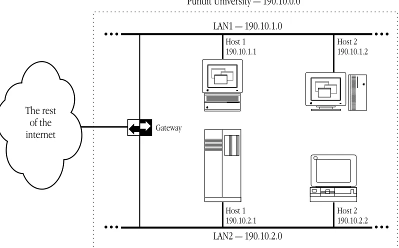
Consider how Pundit University has subdivided its assigned Class B internet address, 190.10.0.0, for the two LANs on campus. They divided the local field of the address into an 8-bit subnet identifier and an 8-bit host identifier. LAN1 has the address 190.10.1.0 and LAN2 has the address 190.10.2.0. Figure 3-2 illustrates the addressing scheme at Pundit University.
In the figure, the rest of the internet perceives that it is sending data to one network. The gateway routes packets to the appropriate LAN by examining the third field in the address.
Figure 3-2 Subnetting at Pundit University
LAN1 — 190.10.1.0
LAN2 — 190.10.2.0
Host 1 190.10.1.1
Host 2 190.10.1.2
Host 1 190.10.2.1
Host 2 190.10.2.2
Pundit University — 190.10.0.0
Gateway
The rest of the internet
Subnetwork masks
An internet site that has implemented subnet addressing must choose a subnetwork mask (or subnet mask), which is used by network software to identify the host number field from the subnet number and network number fields. The portion of the address to be allocated to the subnet is defined (for example, Pundit University used the third field of the address to identify the subnet). Then bits are set in the 32-bit subnet mask to correspond to the IP address.
A subnet mask bit is set to 1 if the corresponding bit in the internet address is part of the network number and subnet number fields, and to 0 if the corresponding bit in the address is part of the host number field. The subnet mask for a Class A address might be 11111111 11111111 00000000 00000000 (or 255.255.0.0 decimal notation). Since this is a Class A address, octet 1 identifies the network field and octets 2, 3, and 4 identify the local field. The mask demarcates octets 3 and 4 as the host number field; therefore, the system knows that octet 2 of the address identifies the subnet number.
In theory, each LAN at the internet site could have a different number of bits allocated to its subnet field and therefore have different subnet masks. However, it is generally recommended that a given network have a single subnet mask that is the same for all of its component LANs.
The domain name system
Because users would rather refer to machines using meaningful, symbolic names rather than long strings of numbers, the domain name system was created to map internet addresses to names.
The hierarchical naming scheme accommodates a large set of names and allows local autonomy in assigning names. A domain name is divided into subnames (called labels), separated by periods, for instance
english.pundit.edu
In this example, eduis the top-level domain and each label further specifies a
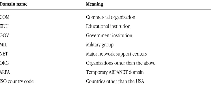
subdomain. The Network Information Center (NIC) administers the top-level domains and is responsible for assigning subdomains. Table 3-1 shows the top-level domains specified by the NIC.
Table 3-1 The top-level domains
Domain name Meaning
COM Commercial organization
EDU Educational institution
GOV Government institution
MIL Military group
NET Major network support centers
ORG Organizations other than the above
ARPA Temporary ARPANET domain
ISO country code Countries other than the USA
After an organization obtains authority for a domain from the NIC, it can assign subordinate domain names. For instance, Pundit University obtained authority for the domain pundit.edu, and the English Department at Pundit University obtained authority for the domain english.pundit.edu.
The organization with authority over a domain must maintain a domain name server that maps domain names to internet addresses. If the English Department at Pundit University obtained a new computer, Hamlet, the name
hamlet.english.pundit.edu
would be added to the database of a domain name server, along with the computer’s internet address.
Hosts participating in the domain name system must have domain name resolvers that request domain name information from domain name servers. The name resolver contacts a local name server to obtain the internet address associated with the domain name. The local name server may need to contact other domain name servers to obtain the internet address.
Address Resolution Protocol (ARP)
The Address Resolution Protocol (ARP) is a protocol in the TCP/IP protocol suite that maps internet addresses to physical network addresses. If Host A wants to communicate with Host B and it only knows the internet address of B, it can use ARP to obtain B’s physical address. Host A broadcasts an ARP request that contains the internet address of Host B. All hosts on the network receive the request, but only Host B recognizes the internet address and replies with its physical address. Host A receives the reply, learns B’s physical address, and delivers its packet directly to B. The following figure shows an ARP request and reply.
Host Z Host A
Host A
Host B Host X Host Y
Host B Host X Host Y
Host Z ARP request ARP request
ARP reply
Reverse Address Resolution Protocol
(RARP)
The Reverse Address Resolution Protocol (RARP) maps physical network addresses to internet addresses (the opposite function of ARP).
RARP provides a way for a host to obtain its internet address. The host broadcasts a RARP request that contains its physical network address. All hosts on the local network receive the request; however, only RARP servers can process the request and provide the internet address. (RARP will work only if there’s a RARP server on the network.) The RARP server consults its database of internet addresses, then sends the information back to the host that made the request. The following figure shows a RARP broadcast and a RARP server reply.
RARP server Host 3
Host 3
Host 1 Host 2 Host 4
Host 1 Host 2 Host 4
RARP server RARP broadcast RARP broadcast
Server reply
Bootstrap Protocol (BootP)
The Bootstrap Protocol (BootP), like RARP, provides a way for a host to find its internet address. A host running BootP broadcasts a BootP request. A BootP server returns a response that contains the internet address of the host, the address of a bootserver, the address of an intervening gateway (if present), and other useful configuration information such as the subnet mask and addresses of domain name servers.
A packet transmitted by a host on the internet may only need to take a short jaunt across
the local network, or it may have to cross many gateways and networks to reach its
destination. The process of finding a path over which the packet can travel to reach its
destination is called routing. This chapter describes how TCP/IP manages routing.
Gateways
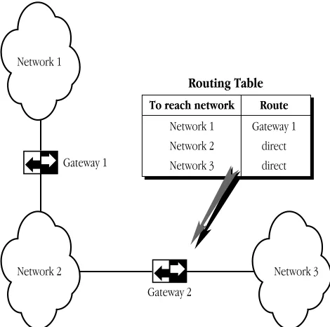
If a host is transmitting to a destination on its own network, routing a packet involves finding the physical address of the destination host (using the Address Resolution Protocol) and sending the packet over the physical network to its destination. When the destination is on a different network, the packet is routed to the nearest gateway. A gateway is a machine that interconnects two networks and passes packets from one network to another. In Figure 4-1, three networks are interconnected by two gateways.
If the local gateway is not connected to the destination network, the packet is forwarded to other gateways until it reaches a gateway that is directly connected to the destination network.
Figure 4-1 Gateways connecting networks
To reach network Route
Network 1 Network 2 Network 3
Gateway 1 direct direct
Routing Table
Gateway 1
Gateway 2
Network 2 Network 3
Network 1
Routing tables
All gateways in the internet have routing tables that contain pairs of network addresses and gateway addresses. Each network address is linked with the gateway address of the gateway to be used to get to that network. Routing decisions are based on the network number of the destination address rather than the host number to keep routing tables small. Figure 4-1 shows an example of a gateway routing table.
Routing protocols
Routing protocols provide a way for gateways to find each other, keep up-to-date routing information, and report communication problems.
Routing Information Protocol (RIP)
Some gateways use the Routing Information Protocol (RIP) to exchange network routing information. Gateways broadcast their routing tables to neighboring gateways. If a RIP message contains new information, gateways update their routing tables.
RIP is intended for low-delay local area networks (LAN), although it is used in wide area networks. A widely used version of RIP is the routed software that is released with the 4.3BSD UNIX®system.
RIP can also be used to locate gateways on a LAN. Any computer broadcasting RIP packets is likely to be a gateway.
Internet Control Message Protocol (ICMP)
Gateways and hosts use the Internet Control Message Protocol (ICMP) to report communication problems. For instance, if a packet cannot be delivered because the destination host is disconnected from the network, an ICMP message may be returned to the sending host stating that the destination is unreachable. ICMP is primarily used by gateways to notify the source host of delivery or routing problems.
ICMP is an integral part of the Internet Protocol (IP). Successful IP routing requires ICMP services to report error conditions. ICMP messages are encapsulated in IP
datagrams, transmitted to the destination gateway or host, and processed by IP software.
This chapter describes how to use MacTCP Admin to configure the MacTCP driver for your
network users. Read the second section “Configuration Tools in MacTCP Admin” before you
start configuration, because that section provides an overview of the MacTCP control panel
and the Administrator dialog box. You use these tools to configure the MacTCP driver.
You can configure the MacTCP software in several ways, depending on how much of the
configuration you want to leave to your network users. Read the section “Configuration
Scenarios” to determine your strategy.
This chapter assumes that you are opening the MacTCP control panel screens for the first
time. If you have configured the driver once, the values that appear will be somewhat
different from those depicted here.
Make sure that you have installed the MacTCP software according to the instructions in
TCP/IP Administration: Overview and Installationbefore you proceed with the tasks
described in this chapter.
The MacTCP Admin and MacTCP files
Recall from the TCP/IP Administration: Overview and Installationmanual that, as network administrator, you have installed a file named MacTCP Admin. The MacTCP and MacTCP Admin files both contain the configuration tools that modify resources in the MacTCP file and the MacTCP Prep file. However, the MacTCP Admin file includes an extra option,
Protected,that leaves the resulting MacTCP file only partially configurable by the user. Since the network administrator should control the option to protect or unprotect the configuration, you should not distribute the MacTCP Admin file to the user. Only the network administrator should use this file to configure the driver. The user can perform either full or partial configuration by running the MacTCP file.
In its default state, the MacTCP file is unprotected. If you plan to give the user full configuration authority, simply distribute the unprotected MacTCP file to the user. Otherwise, use MacTCP Admin to partially or completely configure the driver and protect the configuration, then distribute the MacTCP file to network users.
Configuration tools in MacTCP Admin
MacTCP Admin contains two MacTCP configuration tools: the MacTCP control panel and the Administrator dialog box. The way you use these tools depends on the configuration scenario you choose to implement. (These scenarios are described in the section “Configuration Scenarios” later in this chapter.)
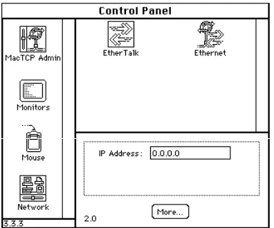
The MacTCP control panel
The top-level configuration tool is the MacTCP control panel. It is used to set link level information and, optionally, to set the IP address in decimal notation. If you set the IP address in the MacTCP control panel, portions of the Administrator dialog box are automatically filled out.
The appearance of the MacTCP control panel in system software version 6.0.x
environment differs from the control panel in version 7.x.However, the function of the MacTCP control panel is the same in either environment.
Figure 5-1 A view of the MacTCP control panel Figure 5-2 A view of the MacTCP in version 6.0.x Admin panel, the MacTCP control
panel in version 7.x
The Administrator dialog box
The lower-level configuration tool is the Administrator dialog box, which is accessed through the More button on the MacTCP control panel.
Figure 5-3 A view of the Administrator dialog box
You use the Administrator dialog box to enter detailed configuration information. The Administrator dialog box in the MacTCP Admin file also allows you to select the Protected checkbox, to protect the configuration from further modification. This option is not available through the Administrator dialog box in the MacTCP file; the checkbox either is dimmed (to indicate that the configuration has been protected) or does not appear.
The Administrator dialog box can be used by the network administrator and by users assigned full configuration authority. Users with partial configuration authority can view the dialog box but cannot modify it.
The following paragraphs give an overview of the Administrator dialog box features.
Obtain Address box
This is where you select the method with which you set the IP address. You have three options:
■ If you select the Manually button, you must fill in some or all of the fields in the IP Address box.
■ If you select the Server button, the IP address for the Macintosh computer is
automatically obtained from a server every time the user starts up the computer. This option requires a RARP or BootP server on an Ethernet, or a MacIP-compatible Datagram Delivery Protocol-Internet Protocol (DDP-IP) gateway on an AppleTalk network.
■ If you select the Dynamically button, the node portion of the IP address for the Macintosh computer is set dynamically every time the user starts up the computer. If you use this option, you must also set some of the fields in the IP Address box.
IP Address box
This is where you set the IP address class, subnet mask, net, subnet, and node numbers. You can fill in some or all of these fields depending on the configuration scenario that you choose to implement.
Routing Information box
This is where you set the gateway address in dotted decimal notation if the Routing Information Protocol (RIP) is not implemented on your network.
Domain Name Server Information box
This is where you set the IP addresses of domain name servers and the domains over which they have authority.
Protected checkbox
If you click this checkbox, the user is not able to modify any of the fields in the Administrator dialog box. The screen is displayed with all the fields dimmed.
Configuration scenarios
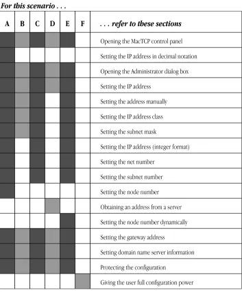
You can configure the MacTCP driver in several ways; you must decide how much of the configuration you want to leave to network users. The following scenarios describe the possible strategies and summarize the configuration process for each. Figure 5-4 shows the chapter sections to which you must refer to accomplish each scenario.
Configure the MacTCP driver so that the user does not have to fill in any IP address information in the MacTCP control panel. If this is your strategy, you have two options. You can set the IP address in the MacTCP control panel (in decimal notation) and then set the subnet information in the Administrator dialog box (if appropriate). Or you can select the Manually button in the Administrator dialog box and then set the IP address class, subnet mask, net, subnet, and node numbers. If you select the latter method, you must configure MacTCP software for each network user.
Configure the MacTCP driver so that the user must fill in the IP address in the MacTCP control panel (in decimal notation). If this is your strategy, select the Manually button in the Administrator dialog box and then set the IP address class and subnet mask. Do not fill in the Net, Subnet, and Node boxes. If you select this method, you can distribute the configured MacTCP software to several users.
Scenario B Scenario A
Configure the MacTCP driver so that the user must fill in the node portion of the IP address in the MacTCP control panel. If this is your strategy, select the Manually button in the Administrator dialog box and then set the IP address class, subnet mask, net number, and subnet number. Do not type the node number in the Node box. If you select this method, you can distribute the configured MacTCP software to several users.
Configure the MacTCP driver so that the address is automatically assigned. (The user does not have to fill in any IP address information in the MacTCP control panel.) If this is your strategy, select the Server button in the Administrator dialog box. If you select this method, you can distribute the configured MacTCP software to several users.
Configure the MacTCP driver so that the node portion of the address is assigned dynamically. (The user does not have to fill in any IP address information in the MacTCP control panel.) If this is your strategy, select the Dynamically button in the Administrator dialog box and then set the IP address class, subnet mask, net, and subnet numbers. If you select this method, you can distribute the configured MacTCP software to several users.
The user is granted full configuration authority and can use the Administrator dialog box to configure the MacTCP software. If you select this scenario, you may distribute the unconfigured MacTCP file. The user should refer to the TCP/IP Connection User’s Guide,
Chapter 3, “Configuring MacTCP.”
The remainder of this chapter describes the steps you must take to accomplish the configuration scenario you have selected.
Scenario F Scenario E Scenario D Scenario C
Figure 5-4 A road map to configuration scenarios
The shaded squares under each scenario indicate the sections of this chapter you should read to accomplish that scenario.
. . . refer to these sections
Opening the MacTCP control panel
Setting the IP address in decimal notation
Opening the Administrator dialog box
Setting the IP address
Setting the address manually
Setting the IP address class
Setting the subnet mask
Setting the IP address (integer format)
Setting the net number
Setting the subnet number
Setting the node number
Obtaining an address from a server
Setting the node number dynamically
Setting the gateway address
Setting domain name server information
Protecting the configuration
Giving the user full configuration power
A B C D E F
For this scenario . . .
Opening the MacTCP control panel
This section describes how you open the MacTCP control panel in system software versions 7.xand 6.0.x.Read the section that applies to your environment.
Version 7
.x
environment
Choose Control Panels from the Apple menu, and the Control Panels window appears with a scrollable list of icons as shown here:
Double-click the MacTCP Admin icon (it may be necessary to use the scroll bar to bring the icon into view). The MacTCP Admin control panel appears, as shown in the following figure. This panel serves as the MacTCP control panel.
Version 6.0
.x
environment
Choose Control Panel from the Apple menu, and the panel appears with a scrollable list of icons at the left side of the window.
Click the MacTCP Admin icon (it may be necessary to use the scroll bar to bring the icon into view). The MacTCP control panel appears to the right of the window as shown in the following figure.
Setting link level information
The top half of the MacTCP control panel displays the available link level protocols on which the MacTCP driver can run. Different icons are displayed depending on your network configuration.
If your Macintosh computer is using an Ethernet interface card, make sure that the software for the card is installed. The MacTCP control panel also provides a way for you to learn the hardware address of your Ethernet interface card if you should need this information for purposes of troubleshooting. Press and hold down the option key and click the Ethernet icon. The hardware address of the card is displayed beneath the icon, as shown here:
Five possible network configurations are described on the following pages. Select the one that applies to your network and follow the instructions to set the link level information.
◆ Note This section is provided to help you set the link level information for your own computer. You cannot remotely perform this configuration task for users because it involves specific information that is reported to the MacTCP control panel by the computer. The TCP/IP Connection User’s Guide includes these instructions. (The User Instructions file includes a less detailed description.) A note advises users to contact you if they have questions about their network configuration or the zone where the DDP-IP gateway is located. ◆
Network configuration 1
The following figure illustrates one possible network configuration: a Macintosh computer on an AppleTalk network using LocalTalk cable with a gateway to an internet.
If this is your network configuration, the upper section of the MacTCP control panel contains the following icon.
The box beneath the icon displays the network zone where your DDP-IP gateway is located. If your gateway is located in another zone, direct the pointer to the zone box beneath the icon and press the mouse button. A pop-up menu appears with a list of zone names as shown in the following figure. Holding the mouse button down, drag the pointer to the list and highlight the appropriate zone. When you release the mouse button, the pop-up menu disappears, and the zone name you selected appears in the box.
Ethernet LocalTalk
TCP/IP host
DDP-IP gateway
Network configuration 2
The next figure illustrates a second possible network configuration: a Macintosh computer with one Ethernet NB Card on an AppleTalk network using Ethernet cable.
AppleShare file server
TCP/IP host Contains one
Ethernet NB Card
If this is your network configuration, the upper section of the MacTCP control panel contains the following icons. Select the Ethernet icon to allow your Macintosh computer to use TCP/IP to communicate with other TCP/IP hosts on the network. (AppleTalk is already being used to communicate with the AppleShare file server and the LaserWriter printer.)
Network configuration 3
The next figure illustrates a third possible network configuration: a Macintosh computer with two Ethernet NB Cards (located in slots 4 and 5) on an AppleTalk network using Ethernet cable.
AppleShare file server
TCP/IP host
Contains two Ethernet NB Cards
If this is your network configuration, the upper section of the MacTCP control panel contains the following icons. (If the Ethernet NB Cards are located in slots other than 4 and 5, the numbers in the icon names will be different.) Select the Ethernet (5) icon to allow your Macintosh computer to use TCP/IP to communicate with other TCP/IP hosts on that network.
Network configuration 4
The next figure illustrates a fourth possible network configuration. Macintosh computers 1, 2, and 3 are on EtherTalk cable segments separate from the TCP/IP host. These computers use AppleTalk protocols to communicate with the gateway, and the gateway uses TCP/IP protocols to communicate with the TCP/IP host. Macintosh computer 4, on the same Ethernet as the TCP/IP host, uses standard TCP/IP protocols to communicate directly with the TCP/IP host.
If this is your network configuration, the upper section of the MacTCP control panel contains the following icons. If you must go through a gateway to reach a TCP/IP host (as do computers 1, 2, and 3 in the previous illustration), make sure that the EtherTalk icon is selected. If you are on the same Ethernet as the TCP/IP host (as is computer 4), select the Ethernet icon.
TCP/IP host
DDP-IP gateway
2
1
AppleTalk router
3
4
Network configuration 5
The following figure illustrates a fifth network configuration: A Macintosh computer on a Token Ring network, connected either to an IP host on the Token Ring network or to an IP host on an Ethernet network through an IP router or Ethernet–to–Token Ring bridge.
If this is your network configuration, the upper section of the MacTCP control panel contains the following icons. Select the Token Ring icon to allow your Macintosh computer to use TCP/IP to communicate with other TCP/IP hosts on that network.
Ethernet
Token Ring network
TCP/IP host
TCP/IP host AppleShare file server Generic IP router or
Ethernet–to–Token Ring bridge
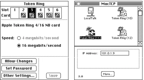
◆ Note If you have a Token Ring card installed in your computer, the Token Ring icon that appears in the MacTCP control panel includes the NuBus slot number. This number differs from the physical card slot number that is displayed in the Token Ring control panel. Figure 5-5 shows the Token Ring and MacTCP control panels for a Macintosh II computer with multiple Token Ring cards. Figure 5-6 maps the correspondence between the physical slot numbers shown in the Token Ring control panel and the NuBus slot numbers shown in the MacTCP control panel. ◆
Figure 5-5 Multiple Token Ring cards in a Macintosh II computer, as seen in the Token Ring and MacTCP control panels
Figure 5-6 Physical slot numbers (shaded) and NuBus slot numbers in various Macintosh computers
Adjusting the MTU size
The current version of the MacTCP Token Ring Extension software supports a Maximum Transmission Units (MTU) size of 2002 bytes for Token Ring network speeds of both 4 megabits per second (Mbits/second) as well as 16 Mbits/second. However, the MTU size can actually be much bigger than 2002 bytes for 16 Mbits/second speed networks. Administrators who want to take advantage of their faster networks can modify the default MTU size of the MacTCP Token Ring Extension software by using the MacTCP Token Ring MTU Tool included on the TCP/IP Administration disk. If you want to adjust the MTU size, copy the MacTCP Token Ring MTU Tool file from the TCP/IP
Administration disk onto your hard disk.
If you distribute the MacTCP Token Ring MTU Tool to users, be sure to instruct them about its use. The user should consult the network administrator before changing the MTU size. Other hosts or routers connected to the ring may not support the new MTU size, causing interoperability problems in the network environment.
9 10 11 12 13 14
9 10 11 12 13 14
Computer model Macintosh II Macintosh IIx Macintosh IIfx Macintosh IIcx Macintosh IIci
Macintosh Quadra 700
Macintosh Quadra 900
Slot 1 Slot 2 Slot 3 Slot 4 Slot 5 Slot 6
9 10 11 12 13 14
9 10 11
12 13 14
13 14
10 11 12 13 14
To adjust the MTU size of your computer, perform the following steps:
1
Open the MacTCP Token Ring MTU Tool by double-clicking the icon for the tool.2
Click the Open button and open the MacTCP Token Ring Extension file using the standard file dialog box.The MacTCP Token Ring MTU Tool displays the current setting as the default MTU size.
3
Change the default MTU size.The default MTU size is 2002 bytes. Change it by typing the new size in the New MTU size box.
4
Click the Close button.A dialog box appears, asking if you want to save the changes. Click the Save button. Then click the Quit button.
5
Restart the computer to use the new MTU size.Setting the IP address in decimal notation
If you have decided to set the entire IP address for the user and you prefer to set the address in dotted decimal notation (for example, 132.10.3.1), type the address in the IP Address box as shown here:
When you click the More button and the Administrator dialog box is displayed, the class, address, and net and node numbers are set, as shown in the following figure.
◆ Note Setting the address in the MacTCP control panel does not set the subnet mask.◆
Opening the Administrator dialog box
Click the More button on the control panel to get to the Administrator dialog box, illustrated here. This panel is your main tool for configuring the MacTCP driver.
Setting the IP address
The Administrator dialog box provides you with three ways to set the IP address (if you did not set the decimal address in the MacTCP control panel). The Obtain Address box in the upper-left corner of the panel (shown here) allows you to select your preferred method for setting the address. Your selection determines whether the user must type the address information on the MacTCP control panel.
■ If you select Manually, you must set the address manually using the fields in the IP Address box. See the next section “Setting the Address Manually.”
■ If you select Server, the address is obtained automatically from a server. This option requires a RARP or BootP server on an Ethernet, or a MacIP-compatible Datagram Delivery Protocol-Internet Protocol (DDP-IP) gateway on an AppleTalk network. See the section “Obtaining an Address From a Server” later in this chapter.
■ If you select Dynamically, you must set the net and subnet portions of the address using the fields in the IP Address box, but the node portion of the address will be allocated dynamically (within the range of node numbers specified). See the section “Setting the Node Number Dynamically” later in this chapter.
◆ Note If you do not set the IP address in either the MacTCP control panel or the Administrator dialog box, then the user must type it in decimal notation on the MacTCP control panel. ◆
Setting the address manually
If you select the Manually option, you must set the address manually using the fields in the IP Address box. You can set either the entire IP address, or the net and subnet portions. Setting the entire address causes the IP address to appear on the MacTCP control panel. The user does not need to type any address information. Setting the net and subnet portions causes Net, Subnet,and Nodeboxes to appear on the MacTCP control panel. The user must type the node number.
To set the address manually, click the Manually button located in the Obtain Address box. Then follow the steps described in the following sections.
Setting the IP address class
Move to the IP Address box and position the pointer on the Class box. Class A, the default setting, is currently in the box. Press the mouse button, and a menu of classes appears as shown here. The ✓indicates which class is the current setting. If you want to change the class, drag the pointer to B or C.
If you change the class, the new value that appears in the Net box is the minimum value allowable for the selected IP address class. For instance, if you select class C, the value in the net box changes to 12582912, which is the minimum value that can be used for class C addresses.
Note that changing the class causes the slider on the ruler to move. The address, subnet mask, and bits allocated to net, subnet, and node also change. The following figure shows the address, subnet mask, position of the slider, and the bit allocation for each class.
Setting the subnet mask
Perform this step only if you have implemented subnet addressing on your network. Use the slider on the ruler to set the subnet mask. Each box in the ruler represents one bit of the 32-bit IP address. A dark vertical line on the ruler indicates the number of bits allocated to the net portion of the address (as determined by the class selected). The slider can be moved anywhere along the ruler to the right of this darkened line. Place the pointer on the slider, hold down the mouse button, and drag the slider to the appropriate location on the ruler. When you move the slider, the subnet mask, the subnet bits, and the node bits change.
If you do not move the slider, the Subnet box remains dimmed.
s Important If you want the user to set the IP address in the IP Address box of the MacTCP control panel (scenario B in the earlier section “Configuration Scenarios”), skip the next section. Continue with the configuration, referring to the section “Setting the Gateway Address” later in this chapter. The user will have to set the IP address in the MacTCP control panel as described in the user’s guide. s
Setting the IP address (integer format)
In integer format, the IP address is broken down into bits (four sets with eight bits per set). The bits are allocated to net, subnet, and node according to the IP address class and subnet mask, then displayed as a decimal number. For instance, the address 90.25.3.240 broken down into bits, looks like this: 01011010.00011001.00000011.11110000
If the IP address class is A (8 bits compose the net portion of the address) and the subnet mask is 255.255.252.0 (or 14 bits of subnet and 10 bits of node), then the integer form of the address is as follows:
■ Net:90 ■ Subnet:1600 ■ Node:1008
If you want to set the IP address in integer format, type this information in the Net, Subnet, and Node boxes shown here:
s Important If you are configuring the MacTCP driver so that the user has to type the node number in the MacTCP control panel (scenario C in the earlier section
“Configuration Scenarios”), you must set the net and subnet portion of the address in integer format in the Net and Subnet boxes. s
Setting the net number The Net box contains the lowest net number that can be used, determined by the IP address class that was selected. Click twice in the Net box and type the net portion of the IP address in integer format. If you type a number over the maximum allowed for the selected IP address class, the last digit in that number is rejected; you must retype a valid number. If you type a number under the minimum allowed for the selected IP address class, a valid number is automatically assigned when you save your changes; therefore, be sure to choose a number over the minimum allowed for the selected IP address class.
If you click the Lock box to the right of the Net box, the net number is protected. The Net box is dimmed, and you cannot change its value unless you click the Lock box to deselect it. If you lock the value in the Net box, the user will not be able to change this number on the MacTCP control panel.
Setting the subnet number Note that you can set the subnet number only if you set the subnet mask. Click the Subnet box and type the subnet portion of the IP address in integer format. If you click the Lock box to the right of the Subnet box, the subnet number is protected. The Subnet box is dimmed, and you cannot change the value in the box unless you click the Lock box to deselect it. If you lock the value in the Subnet box, the user will not be able to change this number on the MacTCP control panel.
Setting the node number You now have three choices: set the node number, leave the Node box at the default and have the user set the node number, or have the node number assigned dynamically.
If you decide to set the node number, click the Node box and type the node portion of the IP address in integer format. If you click the Lock box to the right of the Node box, the node number is protected. The Node box is dimmed, and you cannot change the value in the box unless you click the Lock box to deselect it. If you lock the value in the Node box, the user will not be able to change this number on the MacTCP control panel.
If you decide to have the user set the node number in the MacTCP control panel, leave the default number in the box, and do not select the Lock box. Then continue with the configuration, starting with the section “Setting the Gateway Address” later in this chapter.
If you want the node number to be assigned dynamically every time the user starts up, see the section “Setting the Node Number Dynamically” later in this chapter.
Obtaining an address from a server
If you select the Server button in the Obtain Address box, the network address is obtained automatically from a network server. On an Ethernet network, the protocols BootP or RARP are used to set an address. On an AppleTalk network, a DDP-IP gateway sets the address.
To have a server provide the address, click the Server button in the Obtain Address box. ( When you bring up the Administrator dialog box for the first time, Server is the default setting.) There is no need to set class, subnet mask, net, subnet, or node numbers; the server does it for you. The Macintosh computer that uses this configuration is assigned an address every time it starts up, as long as you have a properly configured server.
After you restart, the class, subnet mask, net, subnet, and node numbers assigned by the server are reflected in the Administrator dialog box and in the IP Address box. The user does not have to set any address information.
Setting the node number dynamically
If you select the Dynamically button in the Obtain Address box, the node portion of the IP address is allocated dynamically within the range of node numbers specified.
An IP address has a range of valid node numbers that are determined by the IP address class and subnet mask. With dynamic addressing, the MacTCP software randomly selects a node address in that range and, using ARP, broadcasts to other nodes on the network, “Is there anyone out there using this address?” If there is no response, that node number is used; if there is a response, the software rebroadcasts until it finds a number that is not being used by other machines on the network.
To use dynamic addressing, set the IP address class, subnet mask, and net and subnet numbers as described in the earlier section “Setting the Address Manually.” Click the Dynamically button in the Obtain Address box. Two boxes appear showing the range of valid node numbers determined by the class