ISSN (Print) : 2320 – 3765 ISSN (Online): 2278 – 8875
I
nternational
J
ournal of
A
dvanced
R
esearch in
E
lectrical,
E
lectronics and
I
nstrumentation
E
ngineering
(An ISO 3297: 2007 Certified Organization)
Vol. 4, Issue 4, April 2015
A Novel
Design and Development of
Rectangular Microstrip Antenna for
Improvement of Gain and Bandwidth
P. Naveen Kumar
1, S.Chandramma
2, Kishan Singh
3, Nagaraj Kulkarni
4, S. N. Mulgi
5,P.V.Hunagund
5Lecturer in Electronics, Dept of Electronics, Yuvaraja College, University of Mysore, Mysore, Karnataka, India1
Associate Professor in Electronics, Dept of Electronics, Yuvaraja College, University of Mysore, Mysore, Karnataka,
India2
Associate Professor in E&C Dept, Gurunanak Dev Engineering College, Bidar, Karnataka, India3
Assistant Professor Dept of Electronics, Govt College, Gulbarga, Karnataka, India3
Department of PG Studies and Research in Applied Electronics, Gulbarga University, Gulbarga, Karnataka, India5
ABSTRACT:
This Paper presents the novel design and development of orthogonal cross slot loaded rectangular
microstrip antenna for multiband operation. The multibands are achieved by incorporating orthogonal slot of equal length at optimum place on the conducting patch. By adding two vertical slots on the patch the impedance bandwidth is enhanced in the upper operating band retaining the nature of broadside radiation characteristics .The proposed antenna
may find application in
radar communication.
KEYWORDS:
orthogonal, multiband, impedance bandwidth, radar communication.
I. INTRODUCTION
The microstrip antennas (MSAs) has gained much attention because of the miniaturization requirement of wireless communication system and their significant features such as small size, light weight, low profile, planar configuration
etc., due to this reason MSAsare used invarious application such as synthetic apertureradar (SAR), WLAN, satellite
communication etc, the main limitations of MSAs are their narrow impedance bandwidth and lower gain. Multiband antennas are realized by many techniques like use of parasitic element [1], Method of moment (MOM) [2], array antenna [3], multi resonators [4] monopole technique[5],use of parasitic branches[6]modifying the ground plane[7],dielectric resonators[8],aperture coupling method[9] etc,. The antenna operating more than one band of frequencies is quite attractive because each band can be used independently for receive/transmit application.
Using only single antenna in the multi signal band is better than using the each antenna element in the separate way. Inspite of this a simple slot technique is used to construct the antenna which gives multiband .This technique enhances
the bandwidth and gainwithout changing the nature of broad side radiation characteristics [10].
II. DESIGNING
The art work of proposed antennas is sketched using software Auto-CAD and fabricated using photolithographic process using low cost glass epoxy substrate materials of thickness h=1.66 mm, relative permittivity εr = 4.2.
Figure 1 shows the geometry of conventional rectangular microstrip antenna (CRMA) designed on a substrate are of M × N which is designed by using basic equations available in the literature [11]. The antenna is designed for the resonant frequency of 4 GHz. The CRMA consists of radiating patch of length L and width W the feed arrangement consists of
quarter wave transformer of length Lt and width Wt is used for better impedance matching between the microstripline
feed of length Lf , width Wf and center point (Cp) along the width of the rectangle microstripline patch. At the tip of
ISSN (Print) : 2320 – 3765 ISSN (Online): 2278 – 8875
I
nternational
J
ournal of
A
dvanced
R
esearch in
E
lectrical,
E
lectronics and
I
nstrumentation
E
ngineering
(An ISO 3297: 2007 Certified Organization)
Vol. 4, Issue 4, April 2015
M
N
Fig 1. Geometry of CRMA
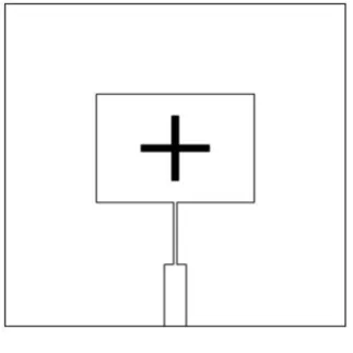
Figure 2 shows the geometry of orthogonal cross slot loaded rectangular microstrip antenna (OSRMA).Here a new concept are introduced by placing the slots one along the width and another along the length by orthogonal cross in the patch. The length of the slot is taken as Ls which is equal to 1cm and width of the slot is Ws which is equal to
0.1cm.The dimension of slots are taken in terms of λ0, where λ0 is the free space wavelengths in cm corresponding to
the design frequency of 4 GHz.
Fig 2. Geometry of OSRMA.
ISSN (Print) : 2320 – 3765 ISSN (Online): 2278 – 8875
I
nternational
J
ournal of
A
dvanced
R
esearch in
E
lectrical,
E
lectronics and
I
nstrumentation
E
ngineering
(An ISO 3297: 2007 Certified Organization)
Vol. 4, Issue 4, April 2015
Fig 3. Geometry of AOSRMA
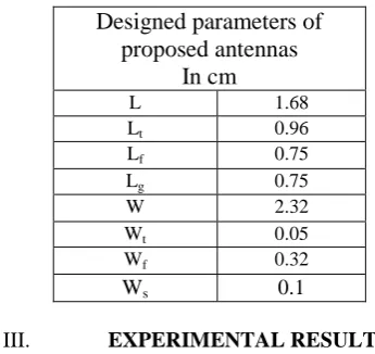
Table 1. Designed parameters of CRMA, OSRMA and AOSRMA.
Designed parameters of
proposed antennas
In cm
L 1.68
Lt 0.96
Lf 0.75
Lg 0.75
W 2.32
Wt 0.05
Wf 0.32
Ws 0.1
III. EXPERIMENTAL RESULTS
The impedance bandwidth over return loss less than -10dB for the proposed antennas is measured on vector network analyzer. The variation of return loss versus frequency of CRMA is as shown in Fig. 4. It is clear from this figure that, the antenna resonates for the design frequency of 4 GHz. This validates the design concept of CRMA. Further from Fig. 4 it is seen that, the antenna resonates for single band of frequency BW1. The magnitude of BW1 is
found to be 3.50 %. This is calculated using the equation,
2 1
Impedance Bandwidth
100 %
c
f
f
f
where f2 and f1 are the upper and lower cutoff frequencies respectively, when its return loss reaches -10dB and fc is the
ISSN (Print) : 2320 – 3765 ISSN (Online): 2278 – 8875
I
nternational
J
ournal of
A
dvanced
R
esearch in
E
lectrical,
E
lectronics and
I
nstrumentation
E
ngineering
(An ISO 3297: 2007 Certified Organization)
Vol. 4, Issue 4, April 2015
-20 -15 -10 -5 0
BW1
5 4
2 0
R
e
tu
rn
L
o
ss
(d
B)
Frequency (GHz)
Fig 4. Variation of return loss versus frequency of CRMA.
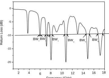
The variation of return loss versus frequency of OSRMA is as shown in fig. 5. From this figure it is seen that, the
antenna resonates for hexaband of frequencies BW2, BW3, BW4, BW5, BW6 and BW7.The magnitude of each operating
band is found to be 0.66 %, 2.36 %, 4.22 %, 3.14 %, 3.15% and 3.95 % respectively. The multiband operationis due
to the independent resonance of Patch and slots inserted in the conducting patch of OSRMA . By the construction of
novel geometry of OSRMA, the antenna starts resonating higher than the designed frequency of 4 GHz.
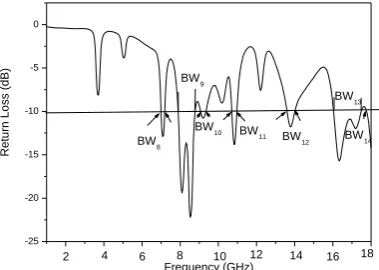
Figure 6 shows the variation of return loss verses frequency of AOSRMA. From this figure it is seen that, the antenna resonates for multi band of frequencies i.e. for BW8, BW9, BW10, BW11, BW12, BW13 and BW14. The magnitude of each
operating band is found to be 1.83 %, 10.18 %, 2.82%, 1.94%, 2.75%, 8.13% and 1.22% respectively. It is clear from
the figure that the upper operating band BW9 is enhanced from 2.36% to 10.18% i.e., BW3 and BW4 are merges in the
Fig. 5 together become BW9 as shown in Fig.6which is 4.31times more than the bandwidth of OSRMA. Further the
upper operating band BW13 isenhanced from 3.97 % to 8.133% as shown in
Fig 6
-20 -15 -10 -5 0
BW6 BW5 BW4 BW3 BW
2 BW
1
18 16 14 12 10 8 6 4 2
R
e
tu
rn
L
o
ss
(d
B)
ISSN (Print) : 2320 – 3765 ISSN (Online): 2278 – 8875
I
nternational
J
ournal of
A
dvanced
R
esearch in
E
lectrical,
E
lectronics and
I
nstrumentation
E
ngineering
(An ISO 3297: 2007 Certified Organization)
Vol. 4, Issue 4, April 2015
r
t 0dB dB
dB t
λ
P
= 10 log
-
- 20log
P
4πR
G
G
where Gt is the gain of the pyramidal horn antenna and R is the distance between the transmitting antenna and AUT.
Using above equation the peak gain of OCSRMA and AOCSRMA measured in their operating bands is found to be 2.02 and 4.25 dB respectively. Hence by the construction of AOCSRMA enhances the gain by 2.10 times more than the
peak gain of OCSRMA
.
-25 -20 -15 -10 -5 0 BW14 BW13 BW12 BW11 BW10 BW9 BW8 18 16 14 12 10 8 6 4 2 R e tu rn L o ss (d B) Frequency (GHz)
Fig 6. Variation of return loss versus frequency of AOCSRMA.
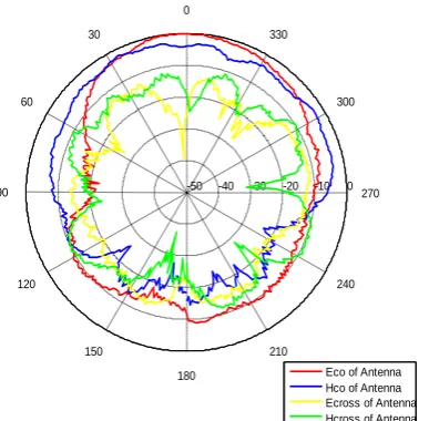
The radiation patterns of antenna are measured in an anechoic chamber. The co-polar and cross-polar patterns in E-
plane and H- plane of the antenna are presented in Fig. 7-9. From these figures it is clear that, the E and H plane patterns are broad sided and are nearly same with each other.
Fig 7. E and H plane radiation patterns of CRMA measured at 3.97 GHz.
0 -10 -20 -30 -40 -50 0 30 60 90 120 150 180 210 240 270 300 330
ISSN (Print) : 2320 – 3765 ISSN (Online): 2278 – 8875
I
nternational
J
ournal of
A
dvanced
R
esearch in
E
lectrical,
E
lectronics and
I
nstrumentation
E
ngineering
(An ISO 3297: 2007 Certified Organization)
Vol. 4, Issue 4, April 2015
Fig 8
. E and H plane radiation patterns of OCSRMA measured at 8.021 GHz.
Fig 9. E and H plane radiation patterns of AOCSRMA measured at 8.02 GHz.
IV. CONCLUSION
From the detailed experimental study it is concluded that, by using orthogonal cross slot in CRMA i.e., OCSRMA
makes the antenna to resonate for hexaband of frequencies and gives a peak gain of 2.02 dB. Further by adding two slots to the OCSRMA i.e., AOCSRMA the antenna resonate for seven band and enhances the gain to 4.25dB when compared to the gain of OCSRMA without changing much in the radiation characteristics. These antenna may find
application in radar communication
.
0 -10 -20 -30 -40 -50 0 30
60
90
120
150
180
210
240 270 300 330
Eco of Antenna Hco of Antenna Ecross of Antenna Hcross of Antenna
0 -10 -20 -30 -40 -50 0 30
60
90
120
150
180
210 240
270 300 330
ISSN (Print) : 2320 – 3765 ISSN (Online): 2278 – 8875
I
nternational
J
ournal of
A
dvanced
R
esearch in
E
lectrical,
E
lectronics and
I
nstrumentation
E
ngineering
(An ISO 3297: 2007 Certified Organization)
Vol. 4, Issue 4, April 2015
3. Levine,E., G. Malamud, S. Shtrikman, and D.Treves, “A study of microstrip array antennas with the feed network,”IEEE Trans.Antennas
and propagation, Vol.37,426-438,1989
4. E.chang, S.A.Long, and W.F. Richard, experimental investigation of electrically thick rectangular microstrip antennas,IEEE Trans
antenna propagation Ap-34 (1986),767-772
5. W.C. Liu and H.-J.Liu,Compact triple band slotted monopole antenna with asymmetrical CPW grounds,Electron Lett 37(2006),840-842.
6. X.Wang,W.Chin, and Z.Feng,Multiband Antenna with parasitic branches for laptop application, Electron Lett 43 (2007),1012-1013.
7. L.Liu, S.Zhu, and R.Langley, Dual band triangular patch antenna with modified ground plane, Electron Lett 43(2007),1012-1013.
8. V.Hamsakutty and K.T. Mathew, Dual Frequency Hexagonal dielectric Resonator Antenna for DCT and WLAN Application, Proc Natl
Symp Antennas Propag 54(2006),199-200.
9. Jazi,M.N.,Z.H.Firouzeh, H.M.Sadeghi, and G.Askari,”Design and Implementation of aperture coupled microstrip IFF antenna,”PIERS
Online,Vol.4,No.1,1-5,2008.
10. Sameena, Konda and Mulgi, “A Novel slot for enhancing the impedance bandwidth and gain of rectangular microstrip antenna”, PIERS C,
Vol.11, pp. 11-19, 2009.