a
Corresponding author: [email protected]
Determination of equilibrium fuel composition for fast reactor in closed
fuel cycle
Mikhail Ternovykh1 a, Georgy Tikhomirov1, Yury Khomyakov2 and Igor Suslov2
1National Research Nuclear University MEPhI (Moscow Engineering Physics Institute), Department of Theoretical and Experimental Physics of Nuclear Reactors, 31, Kashirskoe shosse, 115409, Moscow, Russia
2Institution «Innovation and Technology Center by «PRORYV» Project», State Atomic Energy Corporation Rosatom , 2/8 Malaya Krasnoselskaya Street,107140, Moscow, Russia
Abstract. Technique of evaluation of multiplying and reactivity characteristics of fast reactor operating in the mode of multiple refueling is presented. We describe the calculation model of the vertical section of the reactor. Calculation validations of the possibility of correct application of methods and models are given. Results on the isotopic composition, mass feed, and changes in the reactivity of the reactor in closed fuel cycle are obtained. Recommendations for choosing perspective fuel compositions for further research are proposed.
1 Concept of the reactor project and
criterion functionals considered
The developed algorithms and the results of this work are focused on the concept and design of high power reactors with sodium coolant, uranium-plutonium nitride fuel, high fuel burnup [1-3]. The increased diameter of the core and its significant flattening is typical for such reactors. Fuel assemblies have large fuel elements and increased volume share of fuel in the core. A feature of this concept is to refuse using separated blanket of fuel breeding in the radial and axial direction. Fuel assemblies with increased diameters of fuel rods are used in periferal rows of the core for flattering energy release. Initial fuel load of the same isotopic composition over the reactor is considered.
The reuse of spent fuel in the reactor after cooling and reprocessing is supposed. Fuel is made of the uranium and plutonium from the irradiated fuel assemblies after reprocessing with account of fixed losses during processing. Burnt fuel mass is compensated by depleted uranium and as needed by plutonium with isotopic composition of the starting load of the reactor.
We analyzed the possibility to achieve significant fuel burnup, required uranium and plutonium feeding mass, the change in reactivity between refueling when operating in the described fuel cycle.
2 Methods of estimation of reactor
characteristics in the refueling mode
We considered the following scenario of refueling. The lifetime of the reactor was supposed as 60 years with maximum fuel lifetime of 6 years. Average fuel burnup at
maximum fuel lifetime was 100 MWd/kg. Time of cooling and reprocessing of irradiated fuel was 3 years. The time between refuelings was 1 year (1 microcampaign). 1/6 part of the irradiated fuel assemblies is replaced in each refueling of the core. All fuel assemblies used in initial load and in 1-8 refuelings have the same isotopic composition. After that starting with the 9th refueling (first fuel reprocessing), fuel assemblies have another compositions. Thus, one cycle of fuel assembly is equal to 9 microcompaigns. We analyze the operation of the reactor during at least 60 microcompaigns in this paper.
Such refueling algorithm is extremely complicated, since it should take into account location of fuel assemblies with fresh anf reprocessed fuel in the core, possibility of fuel mix from different irradiated fuel assemblies during processing. Its application requires to keep real track of isotopic composition of many fuel assemblies in the core.
The proposed method of evaluation characteristics of the reactor in the refueling mode is based on calculated properties of fuel assemblies correspondind to average over the core parameters of fuel burnup. Reactor characteristics are predicted by the properties of the core cluster including six fuel assemblies with different properties. Different composition of the fuel assemblies in the cluster is taken into account for all lifetime of the reactor.
We use the term “cluster” in this paper. We mean that cluster is repeating system of elements in horizontal projection of active core larger than fuel assembly. The central element of calculation model of the cluster is assembly channel without fuel consisting of composition of structural materials and coolant. Cluster contains 6 types of fuel assemblies. Each one is a group of fuel
assemblies that were loaded simultaneously in the active core after the next processing. Figure 1 shows the chart of refueling of reactor core (in symmetry of 600). Elements 0 are assembly channels in the reactor core and assemblies of the reactor protection. Elements 1-6 are groups of fuel assemblies which are reloaded simultaneously in active core. The selected clusters demonstrate repeated elements in different radial zones of the reactor.
Fig. 1.Examples of marking of the calculating clusters of fuel assemblies in the active core
The application of this method and its testing was performed with SCALE, MCU, and JARFR program codes. The possibility of application of program code SCALE for solution of the tasks of fuel burnup in reactors with metal coolant is discussed in [4]. The task of changing the isotopic composition was solved using the model of the vertical section of the reactor core. Multi-zone 2-D model tooks into account the axial change of properties of fuel assemblies, structure elements (SE) above and below the core, end leakage from the reactor. Figure 2 presents the calculation model of fuel assembly that take into account the unevenness of change of the isotopic composition in the fuel zones 1-5. Calculations showed that the chosen model allowed us to predict correctly multiplication properties of the entire reactor.
SE (doun) 5 3 1 2 4 SE (top) Fig. 2. Vertical section of the calculation model of fuel assembly.
To obtain isotopic composition and multiplying characteristics of the fuel assemblies during all time of reactor operation, one requires to perform calculations of 7 cycles of irradiation of fuel assemblies consisting of 9 microcampaigns. The numbering of states of fuel assemblies in microcampaigns of the reactor is presented in Table 1. Marked items in the table correspond to the mode of irradiation of the fuel assembly. The rest elements correspond to the mode of cooling and are necessary for modeling of processing of irradiated fuel
and starting composition of fuel assembly of the next cycle. The reprocessing of irradiated fuel is modeled in the following way. All fission products and all isotopes except of uranium and plutonium are removed from the fuel. With account of parameters of the loss of uranium εU and plutonium εPu during the processing, masses of isotopes of these elements used in the next cycle of fuel assembly are determined. Mass of plutonium in the fuel after processing is equal to the initial load of the reactor. The isotopic composition of plutonium feed is the same as in the starting load. The mass of uranium in feed is determined by the condition of conservation of equivalent fuel density.
Table 1. Accordance of fuel assembly state (year) to cycle number of fuel assembly and the number of microcampaign n
n Cycle of fuel assembly
1 2 3 4 5 6 7
1 0 9 18 27 36 45 54
2 1 10 19 28 37 46 55
3 2 11 20 29 38 47 56
4 3 12 21 30 39 48 57
5 4 13 22 31 40 49 58
6 5 14 23 32 41 50 59
7 6 15 24 33 42 51 60
8 7 16 25 34 43 52 61
9 8 17 26 35 44 53 62
Modeling[5-8] of multiplying properties of cluster consisting of 6 fuel assemblies differing by the irradiation time in the reactor is carried out by averaging the multiplication factor of fuel assemblies of the cluster. This approach was justified by a series of direct calculations of realistic models of cluster consisting of 6 fuel assemblies. Analysis of the results was demonstrated that when modeling microcampaign of the reactor, the error in the multiplication factor and the masses of uranium and plutonium in the fuel does not exceed the uncertainty of the results related to the modeling of the geometry of the fuel assembly and irradiation of fuel. The principle of formation of properties of cluster of fuel assemblies during the period of reactor operation is shown in Table 2.
Table 2. Status of fuel assembly in cluster (year) for microcampaign reactor n
n Fuel assembly in cluster
1 0 0 0 0 0 0
2 1 1 1 1 0 1
3 2 2 2 0 1 2
4 3 3 0 1 2 3
5 4 0 1 2 3 4
6 0 1 2 3 4 5
7 1 2 3 4 5 0
8 2 3 4 5 0 1
9 3 4 5 0 1 2
10 4 5 9 1 2 3
11 5 9 10 2 3 4
12 9 10 11 3 4 5
13 10 11 12 4 5 9
14 11 12 13 5 9 10
15 12 13 14 9 10 11
16 13 14 9 10 11 12
17 14 9 10 11 12 13
18 9 10 11 12 13 14
19 10 11 12 13 14 18
20 11 12 13 14 18 19
21 12 13 14 18 19 20
etc.
Fig. 3. Multiplication factor of reactor versus the equivalent fuel density for different start plutonium compositions.
It should be noted that this fact can be explained by the correct account of end leakage in multi-zone 2-D model for the reactor with significant flattening of the core.
3 Results and discussion
Method of evaluation of fast reactor characteristics in the refueling mode was used for the analysis of different fuel compositions. The share of plutonium nitride varied within 12-14%. Equivalent fuel density varied within 11,5-14 g/cm3. Isotopic composition of plutonium corresponded to spent fuel of various thermal and fast reactors [-]. We additionaly analyzed refuelings with initial loads of the reactor on the basis of highly enriched nitride uranium or uranium-plutonium fuel with 239Pu enrichment more than 90%.
Figure 4 presents the results of calculation of the multiplication factor of fuel assemblies of starting load during 6 years of irradiation and 3 years cooling before repeated use of fuel in the reactor. Isotopic composition of plutonium corresponded to real spent fuel of various reactors (curves 1-3). Figure 5 demonstrates the same information for fuel assemblies after the first processing of the fuel. Fuel assemblies of this type have to be loaded into the rector in 9 years of its operation. Note that for the considered fuel compositions, there are intervals of increase and decrease of reactivity during irradiation. This feature allows to compensate for the reactivity change in the reactor when operating in the mode of partial reloading.
Fig. 4. Multiplication factor of fuel assembly versus the time of reactor operation for different start plutonium compositions.
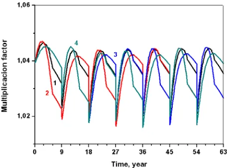
Examples of calculation results for further analysis are presented in Figures 6-7 for plutonium extracted from spent fuel of different reactors (curves 1-3) and for model plutonium (curve 4) and highly enriched uranium (curve 5).
Fig. 6. Multiplication factor of fuel assembly versus the time of reactor operation in the refuelling mode for different plutonium compositions.
Fig. 7. Multiplication factor of fuel assembly versus the time of reactor operation in the refuelling mode for model plutonium and highly enriched uranium compositions.
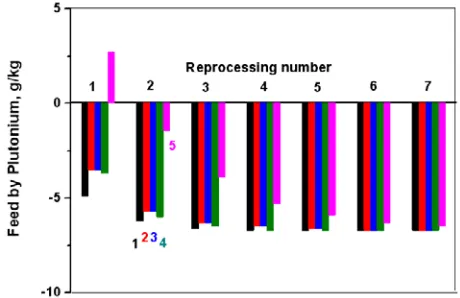
Characteristics of fuel assemblies after 1-7 reprocessing are shown in Table 3. Negative values of feed by plutonium mean that excessive production of plutonium occurs in the considered fuel cycle.
The rate of transition of the fuel composition to the equilibrium in considered mode of processing was determined for different starting isotopic compositions of plutonium including compositions of irradiated fuel of different reactors and model composition with a high content of 239Pu (curve 5). Share of 239Pu in the composition for the considered compounds with the same proportion of the plutonium nitride in the fuel is presented in Figure 8. The mass of the plutonium feed in reprocessing is presented in Figure 9. Note that if the parameter of loss εPu does not exceed 3 %, then for all starting compositions of plutonium from power reactors,
fast neutron high power reactor with nitride fuel will not require plutonium feed but only depleted uranium feed during whole reactor operation.
Table 3. Feed by Uranium and Plutonium (M, g/kg), isotopic composition (X, %) after reprocessing with number N
N MU MPu X238 X239 X240 X241 X242
1 110.4 -3.5 1.3 65.0 25.0 3.9 4.7
2 111.7 -5.7 0.7 65.1 27.1 3.2 3.9
3 112.1 -6.3 0.5 64.8 28.3 3.2 3.3
4 112.3 -6.5 0.4 64.5 28.9 3.2 2.9
5 112.3 -6.6 0.4 64.4 29.3 3.3 2.6
6 112.3 -6.7 0.4 64.4 29.5 3.3 2.4
7 112.3 -6.7 0.4 64.3 29.7 3.3 2.3
Fig. 8. Share of 239Pu after reprocessing of fuel for different
start plutonium compositions.
Fig. 9. Plutonium feed after reprocessing of fuel for different start plutonium compositions.
factor of fuel assembly has a similar form for different values of the share of plutonium nitride. There is an important feature: fuel assemblies of different groups compensate the increase and decrease of reactivity during the reactor operation.
Fig. 10. Multiplication factor of fuel assembly versus the time of reactor operation in the refuelling mode for different share of plutonium nitride.
Additional research was made to evaluate the influence of non-uniformity of the energy release in the reactor and of the difference of compositions of simultaneously reprocessed fuel assemblies on the results of calculations. We considered variant of processing, in which plutonium was placed in the same fuel assembly without mixing with other fuel assemblies. At the same time fuel assembly after processing could be placed from a position with high power density in a position with lower power density and vice versa. Table 4 presents four variants of movement of fuel assemblies over the core under reloading. In these variants, the total fuel burnup has to be the same after 2, 5 and 7 cycle of fuel assembly.
Table 4. Ratio of power of fuel assembly to nominal power (%) for different variants of reloading j
j Number of cycle of fuel assembly
1 2 3 4 5 6 7
1 100 100 100 100 100 100 100
2 125 75 125 75 100 125 75
3 75 125 75 100 125 75 125
4 75 125 100 125 75 125 75
Figure 11 and Table 5 demonstrate that in the mode of reloading characteristics of fuel assemblies depend on the sum fuel burnup and do not depend on their location in the reactor.
According to the results of variant calculations, we selected for the demonstration (Figure 12) starting fuel compositions, which provided the reactor to be critical during the whole time of its operation and provided fast achievement of equilibrium of the fuel composition.
We determined the amount of maximum change of reactivity of the reactor due to fuel burnup between reloading. This value is presented in Figures 13 and 14 in the form of continuous lines for intervals of non-equilibrium and non-equilibrium fuel compositions. Note that for the equilibrium fuel composition change of the reactor reactivity due to fuel burnup does not exceed the delayed neutron fraction and simplifies the regulation of the reactor.
Figure 11. Multiplication factor of fuel assembly versus the time of reactor operation in the refuelling mode for different variants of reloading
Table 5. Multiplication factor of fuel assembly for different variants of reloading in the end of cycle with number N
N 1 2 3 4
2 1.0341 1.0380 1.0251 1.0251
5 1.0352 1.0354 1.0262 1.0385
7 1.0354 1.0390 1.0266 1.0390
Figure 13. The maximum reactivity change of the reactor between the reloading during the first two cycles of the fuel assembly
Figure 14. The maximum reactivity change between reloading after achievement of the equilibrium fuel composition
Note that calculation of the safety parameters of the reactor with equilibrium fuel composition was beyond the bounds of the purposes of this work.
4 Conclusions
These results demonstrate that fuel composition comes into equilibrium concentration in the multiple refueling reactor operation mode. If initial loads were based on plutonium from spent fuel of thermal and fast power reactors, equilibrium was achieved with twice repeated refueling. Initial fuel composition can be fit, which does not require further use of plutonium to compensate burned fuel mass. It is possible to find the mode of formation of secondary fuel and scheme of refuelinf, in which the change in reactivity between refuelings in the equilibrium mode does not exceed the fraction of delayed neutrons.
These conclusions do not apply to initial fuel loads based on highly enriched uranium nitride or uranium-plutonium nitride fuel with high enrichment of 239Pu. For these fuels, equilibrium is reached after 4-5 refuelings.
References
1. V. I Rachkov, V. M. Poplavskii, A. M. Tsibulya, etc. Atomic Energy, 108, 254-259 (2010).
2. V. M. Poplavskii, A. M. Tsibulya, Y. S. Khomyakov, etc. Atomic Energy, 108, 260-266 (2010).
3. G. N. Vlaskin, V. I. Rachkov, Yu. S. Khomyakov, Atomic Energy, 116, 311-315 (2014).
4. A. M. Sirotkin, M. Yu .Ternovykh, G. V. Tikhomirov, M. F. Khromova, Atomic Energy, 116, 330-337 (2014).
5. V.P. Alferov, A.I. Radaev, M. V. Shchurovskaya, G. V. Tikhomirov, N.A. Hanan, F.A. Van Heerden, Ann. Nucl. Energy 77 (2015) 273–280.
6. A.M. Sirotkin, M.Y. Ternovykh, G.V. Tikhomirov, M.F. Khromova, At. Energy 116 (2014).
7. A.S. Gerasimov, V.N. Kornoukhov, I.S. Sald’ikov, G.V. Tikhomirov, At. Energy 116 (2014).
8. D.N. Skorokhodov, G.V. Tikhomirov, Phys. At. Nucl. 75 (2012).
9. A. N. Andrianov, V. G. Baranov, G. V. Tikhomirov, A. V. Khlunov, Atomic Energy, 104, 463-469 (2008). 10. V. G. Baranov, M. Yu. Ternovykh, G. V. Tikhomirov, A. V. Khlunov, Atomic Energy, 105, 391-396 (2008). 11. A. V. Moiseev, Yu. S. Khomyakov, M. Yu. Semenov,
etc., PHYSOR 2010. 2, 1577-1588 (2010).
12. I. R. Suslov, I. V. Tormyshev, O. G. Komlev, Int. Conf. on Mathematics and Computational Methods Applied to Nuclear Science and Engineering, 3, 1655-1663 (2013).